

Page 1
i
USERS GUIDE
Manual Number: 171112
Firmware Version: 00.02
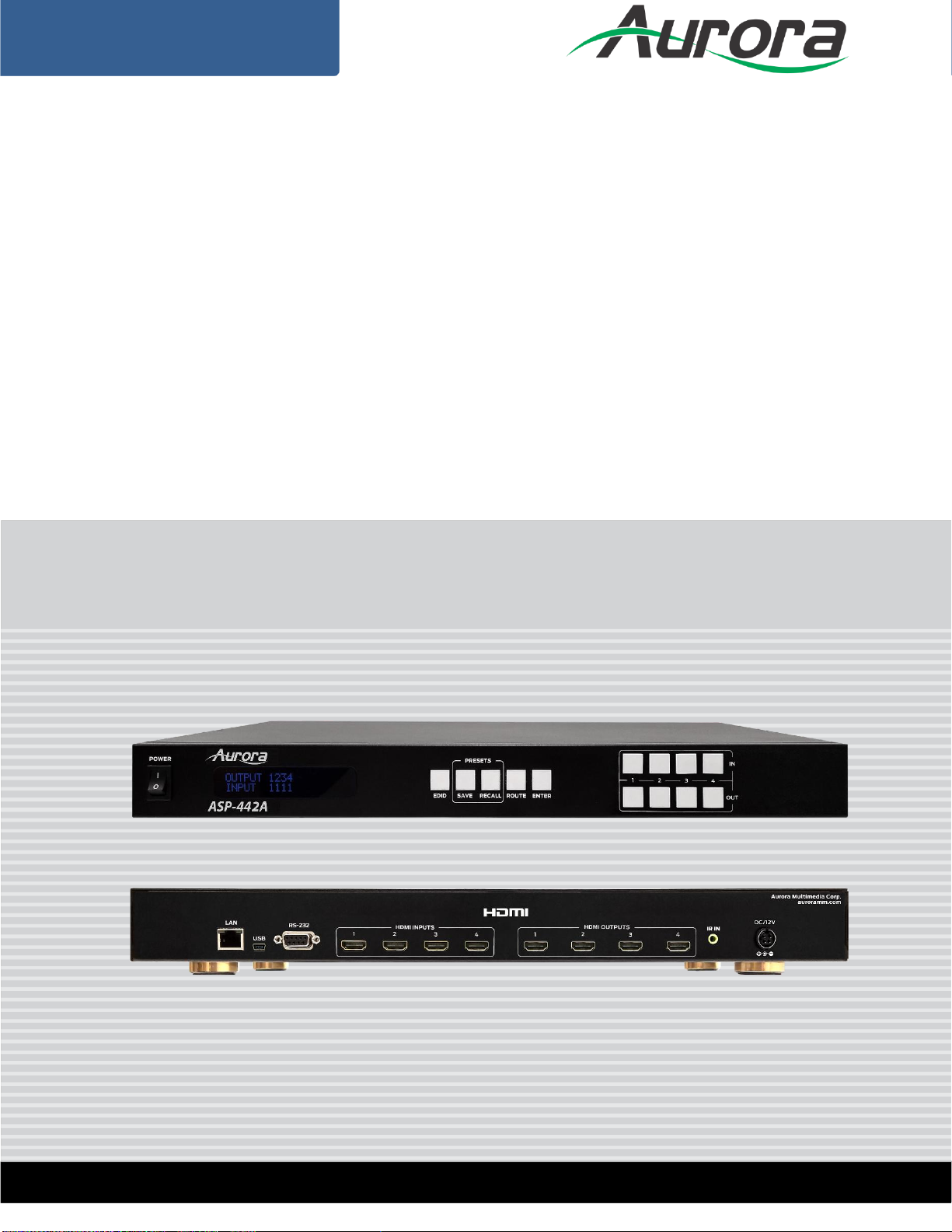
ASP-442A
4x4 Series HDMI 2.0a Matrix
Page 2

i
User Guide
SAFETY INSTRUCTIONS
Please review the following safety precautions. If this is the first time using this model, then read this manual
before installing or using the product. If the product is not functioning properly, please contact your local
dealer or Aurora for further instructions.
The lightning symbol in the triangle is used to alert you to the presence of dangerous voltage
inside the product that may be sufficient to constitute a risk of electric shock to anyone opening
the case. It is also used to indicate improper installation or handling of the product that could
damage the electrical system in the product or in other equipment attached to the product.
The exclamation point in the triangle is used to alert you to important operating and maintenance
instructions. Failure to follow these instructions could result in injury to you or damage to the
product.
Be careful with electricity:
Power outlet: To prevent electric shock, be sure the electrical plug used on the product power cord
matches the electrical outlet used to supply power to the Aurora product. Use only the power adapter
and power connection cables designed for this unit.
Power cord: Be sure the power cord is routed so that it will not be stepped on or pinched by heavy
items.
Lightning: For protection from lightning or when the product is left unattended for a long period,
disconnect it from the power source.
.
Also follow these precautions:
Ventilation: Do not block the ventilation slots if applicable on the product or place any heavy object on
top of it.
Blocking the air flow could cause damage. Arrange components so that air can flow freely. Ensure that
there is adequate ventilation if the product is placed in a stand or cabinet. Put the product in a properly
ventilated area, away from direct sunlight or any source of heat.
Overheating: Avoid stacking the Aurora product on top of a hot component such as a power amplifier.
Risk of Fire: Do not place unit on top of any easily combustible material, such as carpet or fabric.
Proper Connections: Be sure all cables and equipment are connected to the unit as described in this
manual.
Object Entry: To avoid electric shock, never stick anything in the slots on the case or remove the cover.
Water Exposure: To reduce the risk of fire or electric shock, do not expose to rain or moisture.
Cleaning: Do not use liquid or aerosol cleaners to clean this unit. Always unplug the power to the
device before cleaning.
ESD: Handle this unit with proper ESD care. Failure to do so can result in failure.
FCC
This device complies with Part 15 of the FCC Rules. Operation is subject to the following two conditions:
(1) This device may not cause harmful interference.
(2) This device must accept any interferences received, including interference that may cause undesired
operation.
Trademarks
All trademarks in this document are the properties of their respective owners.
Page 3

ii
User Guide
TABLE OF CONTENTS
PACKAGE CONTENTS ............................................................................................................. 1
INTRODUCTION ........................................................................................................................ 2
About ..................................................................................................................................................... 2
Features ................................................................................................................................................ 2
Front ASP-442A .................................................................................................................................... 3
Rear ASP-442A..................................................................................................................................... 4
APPLICATION ........................................................................................................................... 5
ASP-442A Application ........................................................................................................................... 5
OPERATION .............................................................................................................................. 6
LCD Readout ........................................................................................................................................ 6
Routing .................................................................................................................................................. 8
EDID ..................................................................................................................................................... 9
Presets ................................................................................................................................................ 10
Lock Mode .......................................................................................................................................... 10
Show Network Address ....................................................................................................................... 10
Firmware Update ................................................................................................................................. 11
PC Control Software .............................................................................................................. 12
ASP Matrix Manager ........................................................................................................................... 12
SERIAL COMMANDS .............................................................................................................. 17
RS-232 & Telnet Commands .............................................................................................................. 17
APPENDIX 1 Troubleshooting ........................................................................................... 20
APPENDIX 2 Technical Specifications .............................................................................. 21
APPENDIX 3 Warranty ....................................................................................................... 22
Page 4

1
User Guide
PACKAGE CONTENTS
Please make sure the following items are included within your package. Contact your dealer if
any items are missing or damaged.
• ASP-442A x 1
• Rack Ears x 2
• 12v DC Desktop Power Supply x 1
Note: Go to www.auroramm.com for latest manual and firmware
Page 5

2
User Guide
INTRODUCTION
About
The ASP-442A is an 4x4 4K HDMI Matrix offering the power and flexibility you need at a costeffective price. Route Ultra High Definition video sources and multi-channel digital audio from any
of the four (4) HDMI inputs to the any of the four (4) HDMI outputs at the same time. The front
keypad and LCD display are designed for easy operation and quick status of. LAN and RS-232
ports have advanced protocols allowing hot plug detection, signal detection, EDID table
loading/recalling, presets, and more.
The advanced protocol features make the ASP-442A perfect for commercial applications with
auto switching, digital signage with device detection, or residential systems with home
automation.
Features
HDMI 2.0a/HDCP 2.2
Resolutions up to 4K2K 60Hz 4:4:4
HDR High Dynamic Range
HDMI 3D Compliant
HDCP 2.2 Compliant
Allows any source to be displayed on multiple displays at the same time
Allows any HDMI display to view any HDMI source at any time
Supports 7.1 channel digital audio
Advanced EDID Functions
Remote Setup functions via Windows Application
Easy installation with rack-mounting
Front LCD Status Display
Labeling of Inputs, Outputs, and Presets on front display
Page 6
3
User Guide
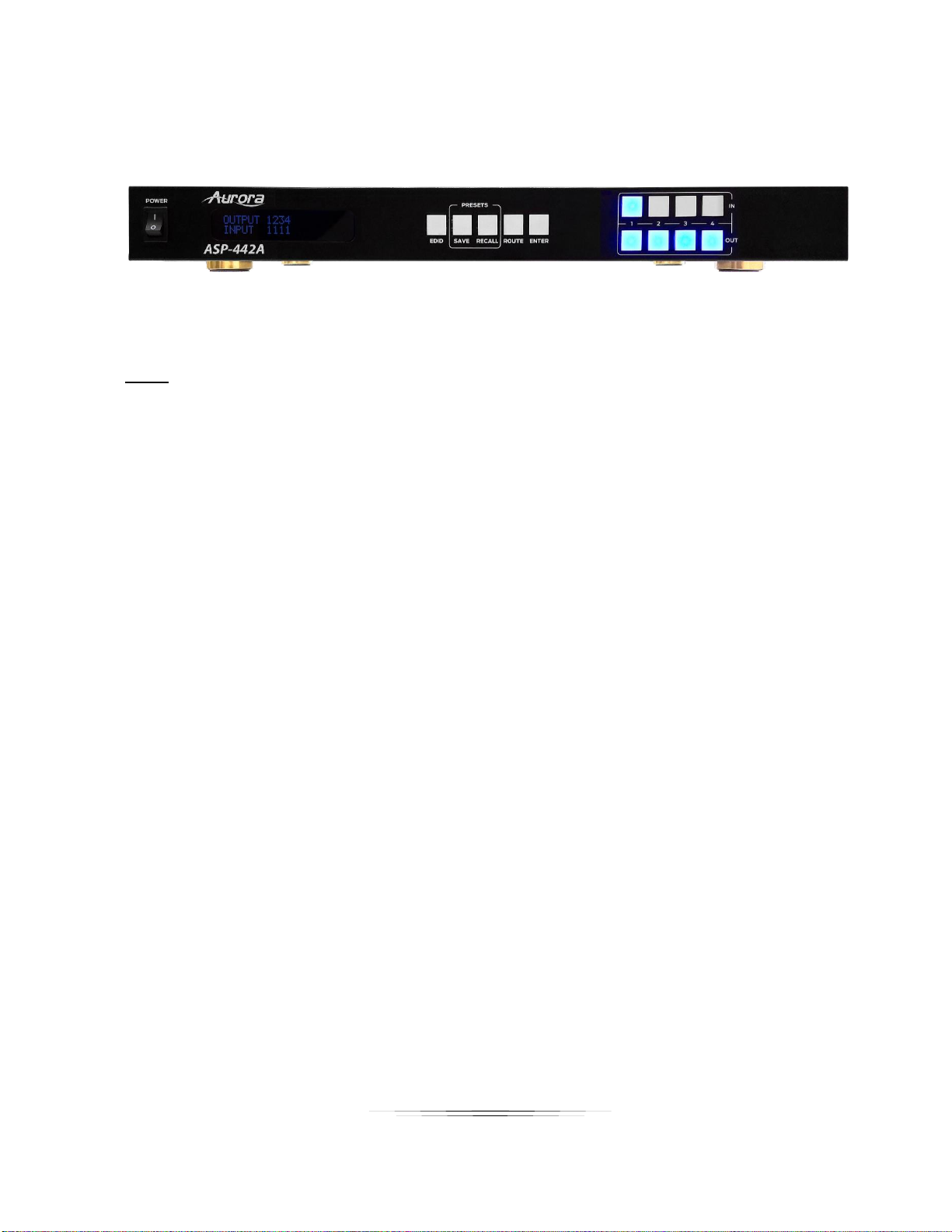
Front ASP-442A
Front
• Power – Power switch for turning the unit on or off. When first turned on all Input and Output
LEDs will light for 1 second to show operation of LED working.
• LCD Display – Top row shows the input routed to relative Output number below.
• EDID – Utilized for setting up the EDID management.
• Save – Preset save function. Press Save for 3 seconds then an Input or Output number to
store a preset into one of the 8 locations of the current routing setup.
• Recall – Preset recall function to restore a saved preset from one of the 8 stored presets.
• Route – When pressed a user can set up any input to any outputs followed by enter for all
the routes to happen at the same time.
• Enter – Used to confirm entries. Also, if pressed with nothing selected, it will show the units
Output connected status, Input connected status, IP address, Subnet Mask, Gateway, MAC,
and Firmware on the LCD.
• Input 1-4 – Input source selections and used with various modes of operation.
• Output1-4 – Output source selections and used with various modes of operation.
Note: Make certain you have the latest firmware for optimal performance and features listed in
manual.
Page 7
4
User Guide
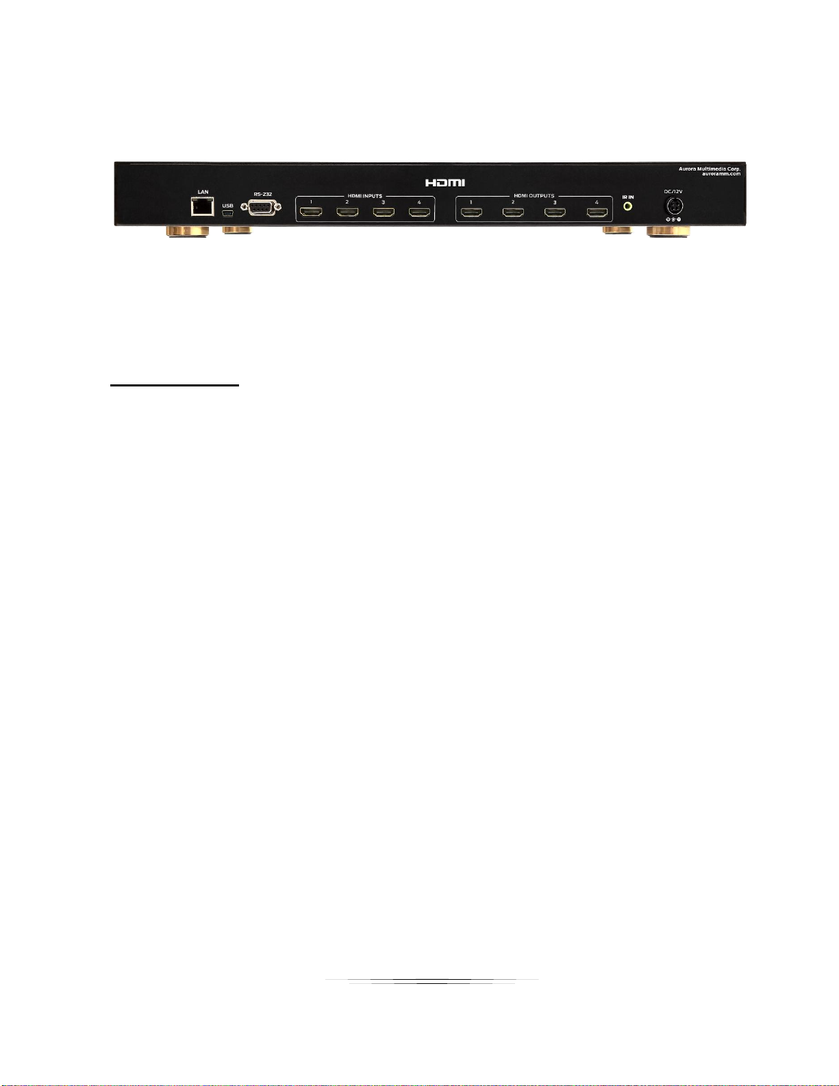
Rear ASP-442A
Rear Connections
• Inputs 1-4 – Four HDMI 2.0a inputs for a variety of sources up to 4K60Hz resolutions.
• Outputs 1-4 – Four HDMI 2.0a outputs for a variety of destinations up to 4K60Hz resolutions.
• LAN - Control remotely using Telnet.
• RS232 – Connect RS-232 device up at 9600 baud for remote control.
• USB – For PC control
• IR IN – Remote control via IR remote with IR receiver unit.
• DC12V – Connect the included 12v DC desktop style power supply.
Page 8
5
User Guide
APPLICATION
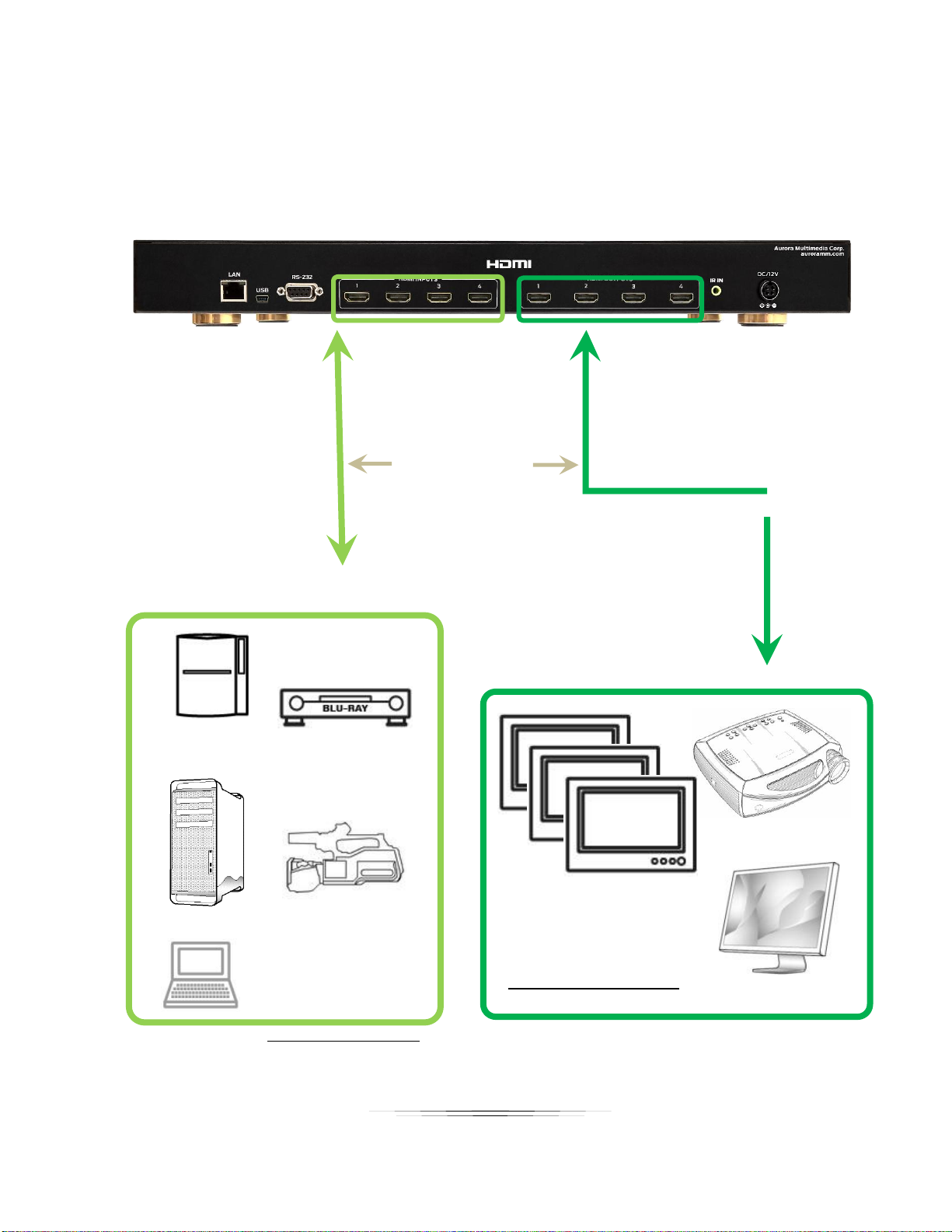
ASP-442A Application
4x HDMI Input
PC or Laptop
4x HDMI Output
PS3
HDMI camcorder
HDMI cables or
Blu-ray disc player
HDTV
HDMI projector
HDMI monitor
Page 9
6
User Guide
OPERATION
LCD Readout
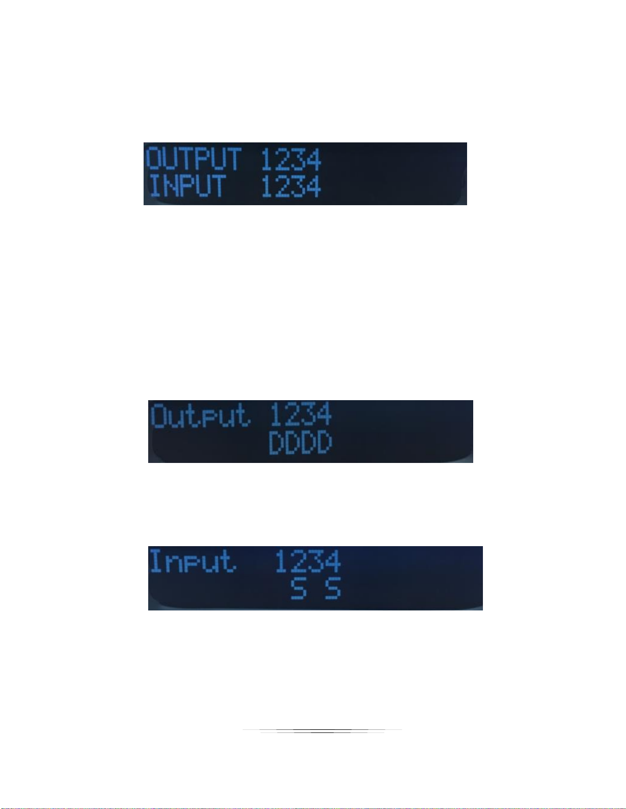
The LCD will reflect what Output is routed to which input when in an idle state. The ASP-442A
(4x4) will only show 1,2,3, & 4 on the LCD unlike the ASP-442A which will show 1-4 since it is
an 4x4.
1-1 If the input/output is not routed, will show “0”
1-2 Press ENTER will turn to next page to check other status as per 1-3 to 1-4.
1-3 Output Connections shows each output with active connected display. If a slash is
underneath, then nothing is connected. If a destination like a display is present a
“D” will show.
1-4 Input Connections shows each input with active connected source. If a slash is
underneath, then nothing is connected or powered. If a source like a PC is
disconnected a “S” will show.
Page 10
7
User Guide
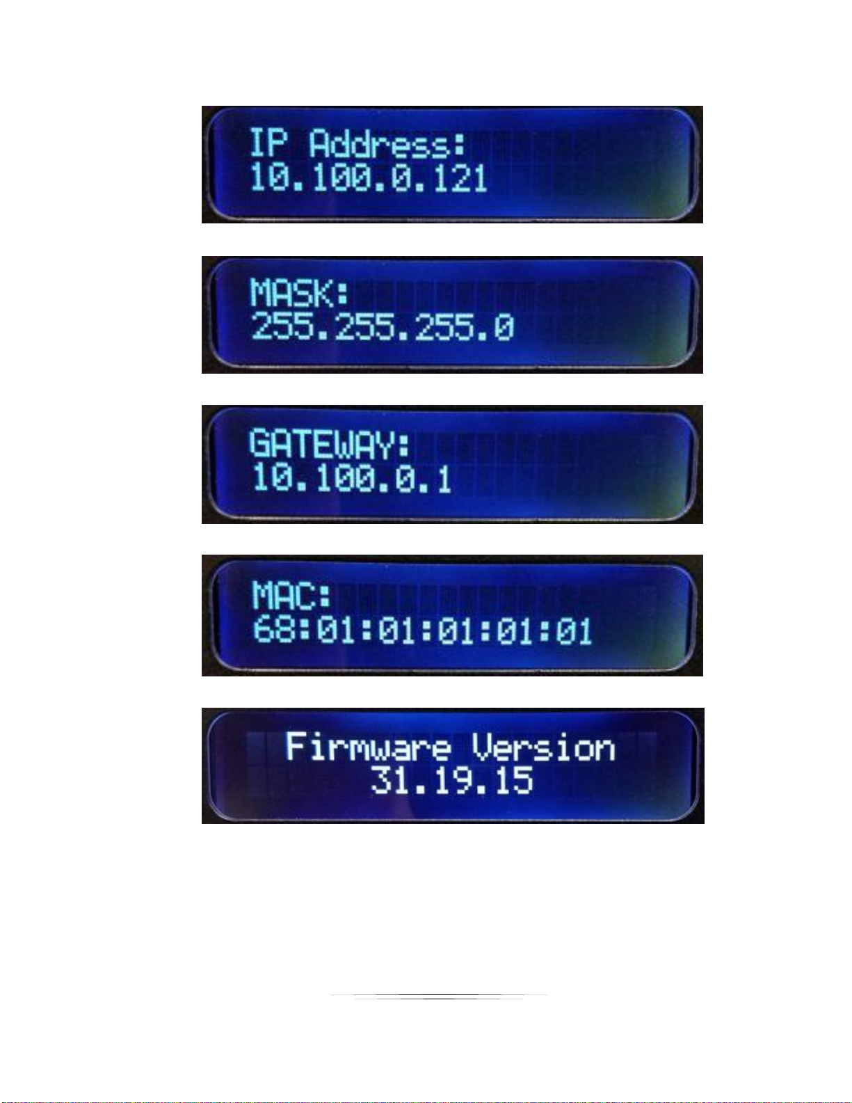
1-5 IP Address
1-6 Subnet Mask
1-7 Gateway
1-8 MAC Address
1-9 Firmware Revision
1-10 Will revert to mapping if do not press any button for 3 seconds
The LCD will also show various states of operation and displaying information depending on the
mode of operation.
Page 11

8
User Guide
Routing
The ASP-442A has 3 ways of making a route for optimal flexibility.
Technique 1
1) Press ROUTE, all the input / output buttons will light for connected HDMI inputs.
2) Press desired input, then the output(s) will light that it is routed to.
3) Select the Output(s) to associate the Input accordingly. To unroute press the already lit
Output(s)
4) Press ENTER to complete the operation and make the routes all at once.
5) Press ROUTE again to do another input setting followed by 1) to 3)
Note: If want to discontinue the ROUTE setting, please press the ROUTE again. The
operation will be canceled when no active button pushes for more than 3 seconds from
last button press.
Technique 2
1) Press an input and it will light along with any output it is currently routed to.
2) Press desired output(s) and it will be routed or unrouted to the selected input
immediately.
Note: The operation will be cleared when no active button pushes for more than 5 seconds
from last button press.
Technique 3
1) Press an output and it will light along with any input it is currently routed to.
2) Press desired input and it will be routed or unrouted to the selected output immediately.
Note: The operation will be cleared when no active button pushes for more than 5 seconds
from last button press.
Page 12

9
User Guide
EDID
1) Press EDID, the LCD will state current mode of operation.
1-1 Press EDID for 3 seconds, will be able to change the mode between Auto
mode/Manual mode.
2) In Manual mode – EDID Learning
2-1 Press the output that needs to be learned.
2-2 The LCD will show “Device ID” of the output.
2-3 Press the input(s) which you want to learn the EDID from the pressed output.
2-4 Press ENTER, the LCD will show “Success” or “Fail” to indicate the learning status.
3) In Manual mode – Default EDID
3-1 Press the OUTPUT 1~4 button for 3 seconds as default 1~4 EDID.
3-2 The LCD will show “Default + mode number”.
3-3 Press the input(s) which you want to learn the default EDID from the pressed
output(default).
3-4 Press ENTER, the LCD will show “Success” or “Fail” to indicate the learning status.
4) In Manual mode – Check input status
4-1 Press the input.
4-2 The learned EDID output number and device ID will show on the LCD.
Note: To discontinue the EDID setting, please press the EDID again. The operation will
be canceled when there is no activity for more than 3 seconds from last button
press.
Page 13

10
User Guide
Presets
SAVE
1) Press SAVE for 3 seconds, the button will light, and the operation will be started.
2) Select from input & output number 1~4 as customized mapping 1~8 sets.
The LCD will show the mapping status of the pressed button.
3) Press ENTER to complete the operation. The current mapping will be saved.
Note: To discontinue the SAVE setting, please press the SAVE again. The operation will
be canceled when there is no activity for more than 3 seconds from last button
press.
RECALL
1) Press recall, the button will light, and the operation will be started.
2) Select from input & output number 1~4 as customized mapping 1~8 sets.
The LCD will show the mapping status of the pressed button.
3) Press ENTER to complete the operation. The mapping you have chosen will be recalled.
Note: If want to discontinue the RECALL setting, please press the RECALL again.
The operation will be canceled when there is no activity for more than 3 seconds
from last button press.
Lock Mode
1) Press ENTER for 3 seconds will enable front panel locked.
2) Holding another 3 seconds will unlock.
3) If locked and any button is pressed, LCD will state “Keypad Locked”.
4) During the lock mode, the LCD will show the mapping status.
Show Network Address
1) Press ENTER to see units IP Address and Subnet Mask on the front LCD. It will show
for 3 seconds or until a user selects another function.
Page 14

11
User Guide
Firmware Update
Firmware can be update by the ASP Matrix Manager software through RS-232
Page 15
12
User Guide
PC Control Software
ASP Matrix Manager
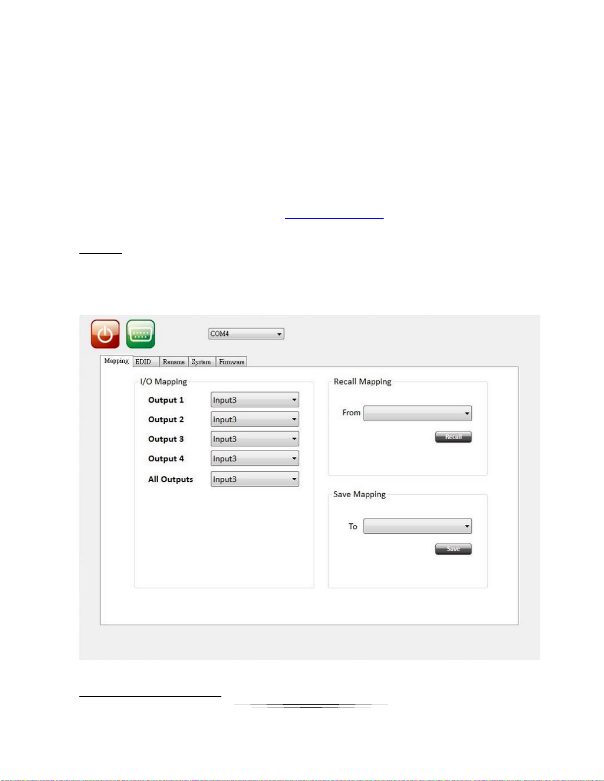
The ASP-442A has a utility called ASP Matrix Manager which allows the setup via RS-232 and
Ethernet Mapping (Routing) of Outputs to Inputs, EDID management, Rename (Labeling
displayed on LCD), System (IP Address Setup), and Firmware (Updating). Note for the ASP-
442A only 4 inputs and outputs will be available and 8 preset locations. It is available for
download from the Aurora customer portal www.auroramm.com
Mapping
The Mapping tab allows the routing of Outputs to the designated input. It also will allow for
presets to be saved and recalled.
Page 16
13
User Guide
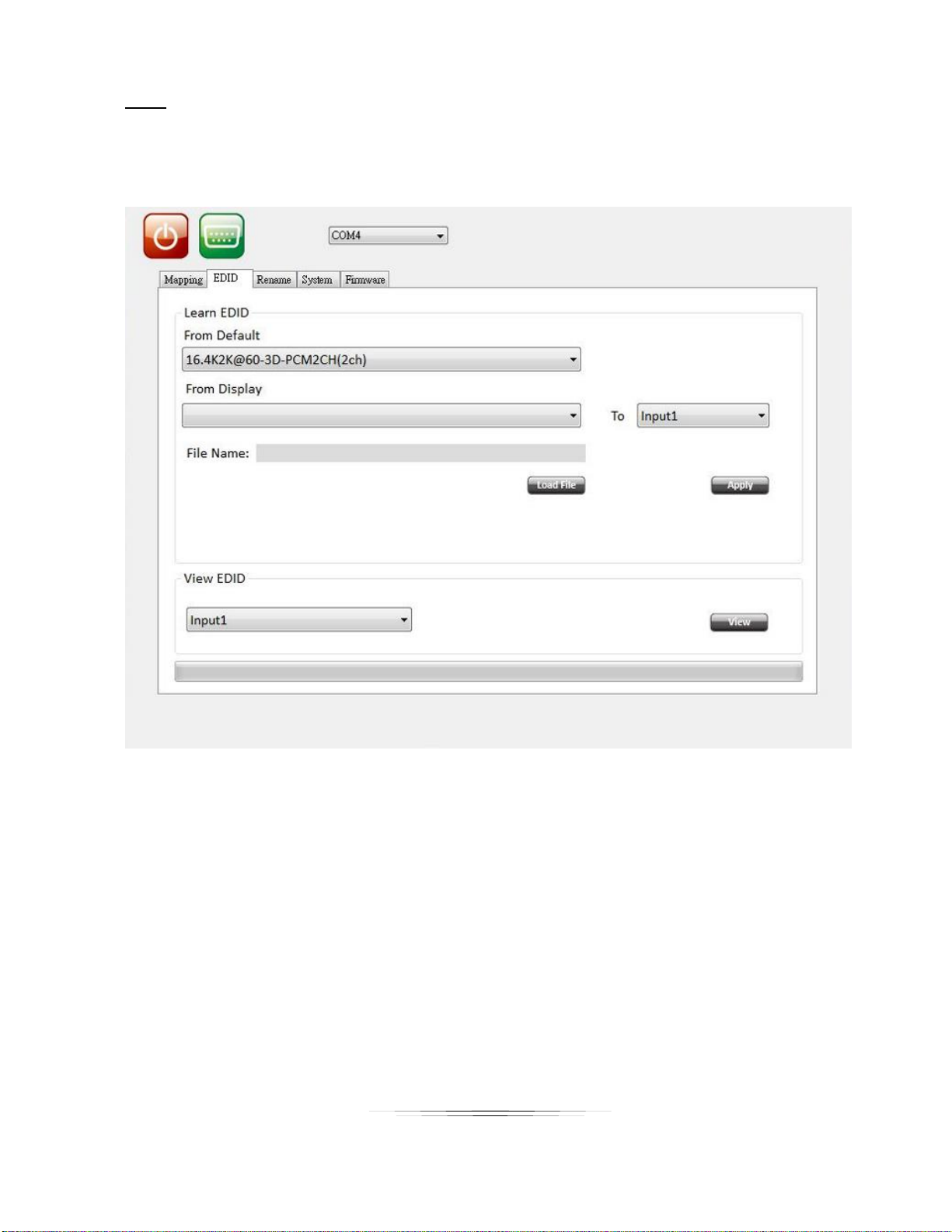
EDID
The EDID tab allows for full EDID management to all the inputs. Custom EDID files can be
loaded from this tab or pulled from a device to be saved for other units.
Page 17
14
User Guide
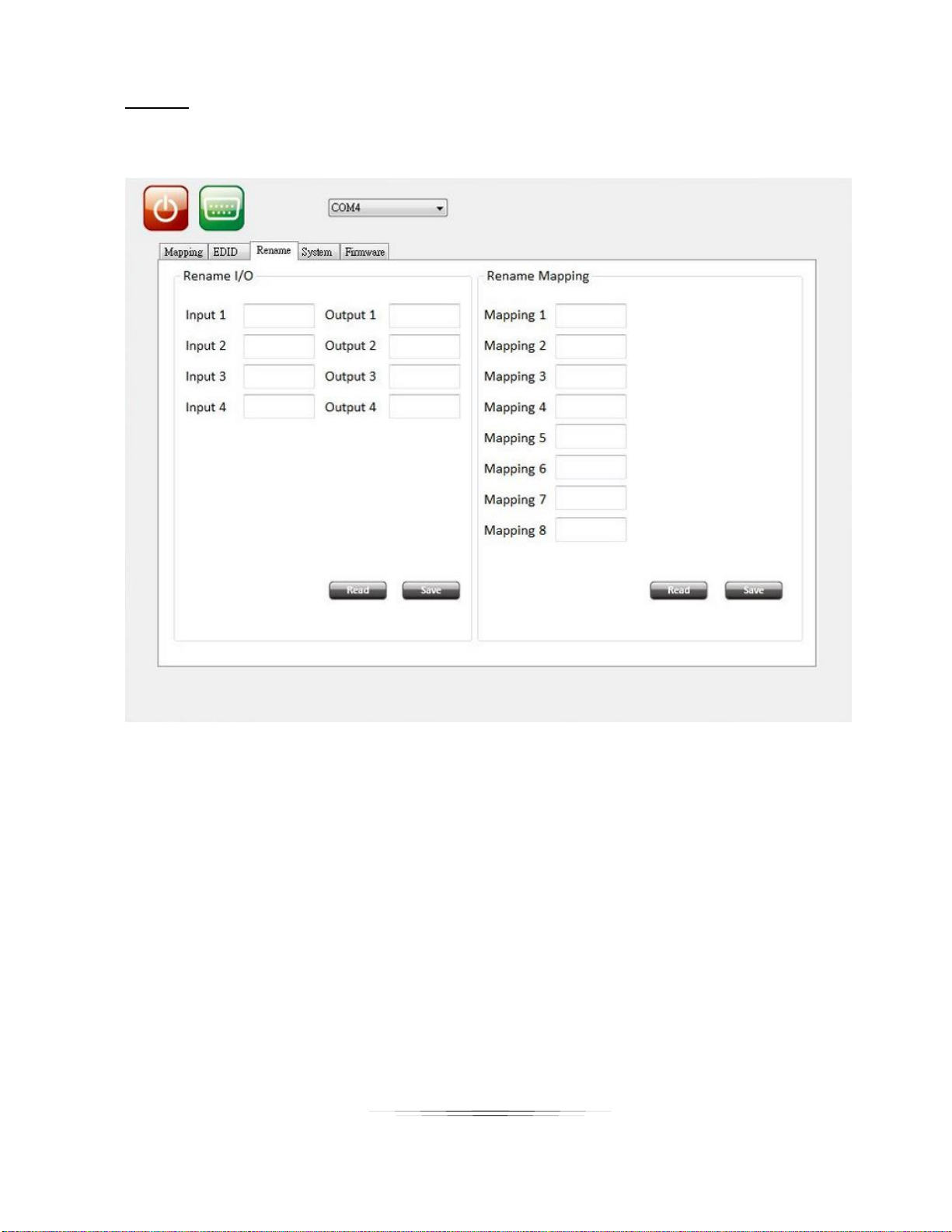
Rename
The Rename tab allows the labeling of Input, Output and Preset buttons on the front LCD.
Page 18
15
User Guide
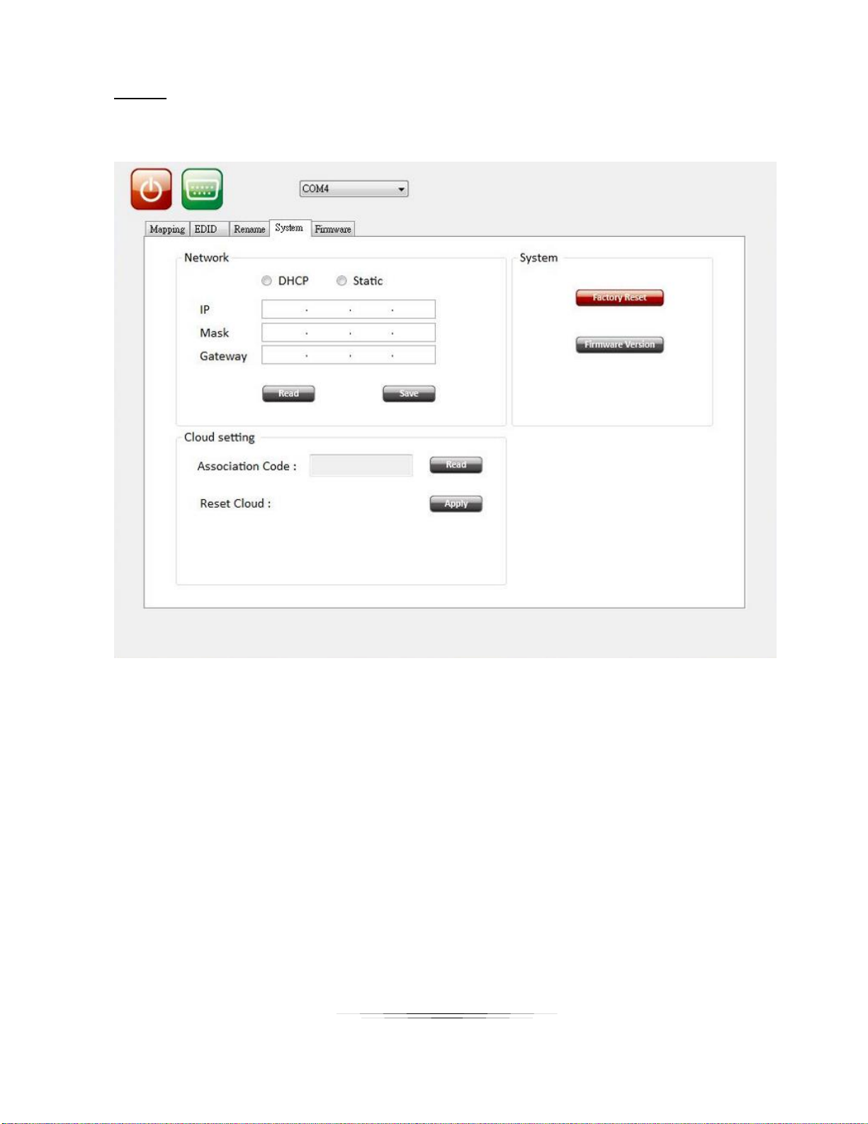
System
The System tab is for the setup of the units IP settings, factory defaults, and firmware versions.
Page 19
16
User Guide
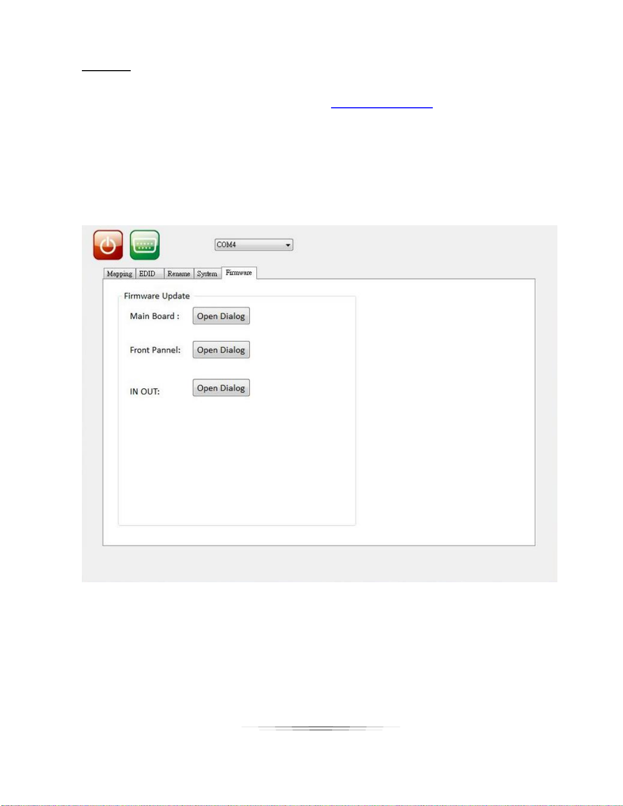
Firmware
The Firmware page allows the updating of firmware from the LAN or USB. Latest firmware can
be found on the Aurora customer portal located at www.auroramm.com
Important! Make certain unit has valid IP address if using Update from Net. If unit is set to
DHCP make certain there is a DHCP server connected or set to a static. If updating from USB
memory stick, only one update file can reside in the root directory. Early firmware may require to
files to be updated (ALL and MB). If it is 2 files the one with ALL in the name must be loaded
first.
Page 20

17
User Guide
SERIAL COMMANDS
RS-232 & Telnet Commands
Baud Rate: 9600 8N1 DB9 Female (Pins 2-TX, 3-RX, 5-GND), Straight through Cable to PC
! is the start character to active a command
? is the start character to query status
~ is the start character of the response
/x0D (<cr> aka carriage return) is the end character
Commands are case sensitive. Capitals only.
Command
String Format
Information
Route
Command
!RTx1 x2 x3 x4<cr>
x1-x8 = output relative to input.
Example: !RT315x8052<cr>
0 = Unroute
X = ignore (do nothing)
In this example
Output 1 is routed to 3
Output 2 is routed to 1
Output 3 is routed to 5
Output 4 is ignored and left alone
Output 5 is routed to 8
Output 6 is unrouted
Output 7 is routed to 5
Output 8 is routed to 2
Response:
~RTx1 x2 x3 x4<cr>
Preset Recall
!PRx<cr>
x = 1-8
Responds: ~PRx<cr>
Preset Store
!PSx<cr>
x = 1-8
Responds: ~PSx<cr>
Query Route
?RT<cr>
Responds with ~RTx1 x2 x3 x4<cr>
x1-x4 = output relative to input. Example: Output
1 is routed to input 3 so position x1 would equal 3.
If nothing is routed to an output then the value
will be 0 (zero).
Firmware
Version
?VR<cr>
Responds with the current firmware version
number
Example ~VR1.00<cr>
Factory Default
!FD<cr>
Responds with ~FD<cr>
IP Address
!IPA-xxx.xxx.xxx.xxx<cr>
x= IP Address ex. 192.168.1.13
Responds with ~IPA-xxx.xxx.xxx.xxx<cr>
Page 21

18
User Guide
EDID Write
!EDWx-y0 y1…y255<cr>
x= HDMI Input 1-4
y0-y255 = EDID Data in ASCII HEX representation
EDID Read
?EDRx<cr>
x= HDMI Input 1-4
y0-y255 = EDID Data in ASCII HEX representation
Response: ~EDIDx-y0 y1…y255<cr>
y0-y255 = EDID Data in ASCII HEX representation
EDID Learn
!EDLx1 x2 x3 x4 x5 x6 x7
x8<cr>
x1-x4 = output relative to input.
Example: !EDL315x80F2<cr>
0 = Clear EDID
X = ignore (do nothing)
F = Factory EDID default
In this example
Input 1 gets output 3 EDID
Input t 2 gets output 1 EDID
Input 3 gets output 5 EDID
Input 4 is ignored and left alone
Input t 5 gets output 8 EDID
Input 6 is cleared
Input 7 is Set to factory default EDID
Input 8 gets output 2 EDID
Response:
~EDLx1 x2 x3 x4<cr>
Factory default EDID should be 1080p 24bit stereo
Front Keypad
Lockout
!KLx<CR>
x = (1=ON, 0=OFF)
Response: ~KL<cr>
HDCP Input
On/Off
!HDCPIN x1 x2 x3 x4 <CR>
x1-x4 = Input relative to HDCP function.
0 = HDCP is forced off. This helps with devices that
always have HDCP on unless it sees there is no key
to exchange.
1 = HDCP is available
Note: Default is HDCP Available
Hotplug Input
Detect
?HPIN<cr>
Detects and reports back if a signal is present at a
specific input. It will also send the response back
automatically if there is a change in state.
Response: ~HPIN x1 x2 x3 x4<cr>
0 = nothing
1 = signal
Hotplug Output
Detect
?HPOUT<cr>
Detects and reports back if a device present at a
specific output. It will also send the response back
automatically if there is a change in state.
Response: ~HPOUT x1 x2 x3 x4<cr>
0 = nothing
1 = signal
VCC Output
Toggle
!VCCOUTx<cr>
1 = Toggle Output VCC5V 100ms
Response: ~VCCOUTx <cr>
Page 22

19
User Guide
Input Label
!LINx-y<cr>
x = 1-4
y = Label Name
Response: ~LINx-y<cr>
Input Label
Query
?LINx<cr>
x = 1-4
y = Label Name
Response: y<cr>
Output Label
!LOUTx-y<cr>
x = 1-4
y = Label Name
Response: ~LINx-y<cr>
Output Label
Query
?LOUTx<cr>
x = 1-4
y = Label Name
Response: y<cr>
Preset Label
!LPRx-y<cr>
x = 1-4
y = Label Name
Response: ~LINx-y<cr>
Preset Label
Query
?LPRx<cr>
x = 1-4
y = Label Name
Response: y<cr>
Note 1: Upon power up or detection of a new device on an output the port should read the EDID to see if
it is DVI connected and if so remove the audio automatically for proper compatibility. This way if the input
EDID is HDMI the HDMI will still work with ports that have DVI connected.
Note 2: If change is made from front panel the appropriate response command should be sent out. For
example if a route was made then the ~RTx1 x2 x3 x4<cr> should be sent automatically. This way
polling is not required.
Note 3: If an input has no HDCP then the output should not have HDCP either unless the force
HDCP command is enable.
Page 23
20
User Guide
APPENDIX 1 Troubleshooting
Problem
Solution
1. LED is not lit on any LEDs or
buttons
a. Check 12v power supply is plugged in rear of unit
b. Check to see if Wall supply is plugged into wall outlet.
c. Make certain wall outlet has power.
d. Make certain switch on rear of unit is on.
2. RS-232 does not work
a. Check connection on RS-232 port. Make certain TX goes to RX and
RX goes to TX of the device to be connected. Don’t forget about
ground.
b. Check baud rate.
c. Verify commands being sent are correct protocol.
3. Some functions do not work
a. Make certain unit has latest firmware.
Page 24
21
User Guide
APPENDIX 2 Technical Specifications
Model Name
ASP-442A
Technical
ASP-442A
RS-232 Baud Rate
9600 8N1
DB9 Female (Pins 2-TX, 3-RX, 5-GND), Straight through Cable to PC
Front Panel
Blue Backlit LCD and Selection Keys
Bandwidth
600MHz
Resolutions
480i / 480p / 720p / 1080i / 1080p60 8-12 bit color / 3840x2160 @ 30Hz / 4Kx2K @
30Hz / 4Kx2K @ 60Hz
HDCP Compliant
1.4 and 2.2
HDMI Output Distance
1080p up to 20m, 4K30Hz up to 10m, 4K60Hz up to 5m
Note: Cable quality may impact distance
HDMI Connector
Type A (19 Pin Female)
RS-232 Connector
DB-9 Female
LAN Port
RJ-45 (Telnet Communications)
Mechanical
ASP-442A
Housing
Mental Case
Dimensions
[L x W x D]
17.3" x 6.9" x 1.7" [440 x 176.3 x 42mm]
Weight
5.1lbs (2.315kg}
Mounting
1RU Rack Mount 19” x 1.75”
Power supply
12v 5A DC
Power consumption
25Watts
Operation temperature
0~40C [32~104F]
Storage temperature
-20~60C [-4~140F]
Relative humidity
20~90% RH [no condensation]
Package Contents
1x ASP-442A
1x 12v Desktop Power Supply
2x Rack Mount Ears
Specifications subject to change without notice.
Page 25

22
User Guide
APPENDIX 3 Warranty
Limited 3 Year Warranty
Aurora Multimedia Corp. (“Manufacturer”) warrants that this product is free of defects in both materials and
workmanship for a period of 3 years as defined herein for parts and labor from date of purchase. This Limited Warranty
covers products purchased in the year of 2009 and after. Motorized mechanical parts (Hard Drives, DVD, etc),
mechanical parts (buttons, doors, etc), remotes and cables are covered for a period of 1 year. Touch screen displays
are covered for 1 year; touch screen overlay components are covered for 90 days. Supplied batteries are not covered
by this warranty. During the warranty period, and upon proof of purchase, the product will be repaired or replaced (with
same or similar model) at our option without charge for parts or labor for the specified product lifetime warranty period.
This warranty shall not apply if any of the following:
A. The product has been damaged by negligence, accident, lightning, water, act-of-God or mishandling; or,
B. The product has not been operated in accordance with procedures specified in operating instructions: or,
C. The product has been repaired and or altered by other than manufacturer or authorized service center; or,
D. The product's original serial number has been modified or removed: or,
E. External equipment other than supplied by manufacturer, in determination of manufacturer, shall have
affected the performance, safety or reliability of the product.
F. Part(s) are no longer available for product.
In the event that the product needs repair or replacement during the specified warranty period, product should be
shipped back to Manufacturer at Purchaser's expense. Repaired or replaced product shall be returned to Purchaser
by standard shipping methods at Manufacturer's discretion. Express shipping will be at the expense of the Purchaser.
If Purchaser resides outside the contiguous US, return shipping shall be at Purchaser's expense.
No other warranty, express or implied other than Manufacturer's shall apply.
Manufacturer does not assume any responsibility for consequential damages, expenses or loss of revenue or property,
inconvenience or interruption in operation experienced by the customer due to a malfunction of the purchased
equipment. No warranty service performed on any product shall extend the applicable warranty period. This warranty
does not cover damage to the equipment during shipping and Manufacturer assumes no responsibility for such
damage.
Page 26

23
User Guide
This product warranty extends to the original purchaser only and will be null and void upon any assignment or
Aurora Multimedia Corp.
205 Commercial Court
Morganville, NJ 07751
Phone: 732-591-5800 Fax: 732-591-6801
www.auroramm.com
 Loading...