

Aurora Electronics PVI-3600-OUTD-UK-F-W User Manual

AURORA
Inverters
INSTALLATION AND OPERATOR’S
MANUAL
Model number: PVI-3600-OUTD-UK-F-W Rev. 1.0
Installation and Operator’s Manual Page 2 of 63
(PVI-3600-OUTD-UK-F-W Rev.: 1.0)
REVISION TABLE
Document
Revision
1.0 T. Melzl 5/1/2006 First release of the document
1.1 T.Melzl 5/3/2006 Updated Anti-Inlanding
Author Date Change Description
reference
SAVE THESE INSTRUCTIONS !
IMPORTANT SAFETY INSTRUCTIONS
MAGNETEK: Reproduction and disclosure, even partially, of the contents of
this manual are strictly forbidden without prior authorization of
Magnetek.
Installation and Operator’s Manual Page 3 of 63
(PVI-3600-OUTD-UK-F-W Rev.: 1.0)
IMPORTANT SAFETY INSTRUCTIONS
This manual contains important safety and operational instructions that must be
accurately understood and followed during the installation and maintenance of the
equipment.
To reduce the risk of electrical shock hazards, and to make sure the equipment is
safely installed and commissioned, special safety symbols are used in this manual
to highlight potential safety risks and important safety information. The symbols
are:
WARNING: the paragraphs highlighted by this symbol contain
processes and instructions that must be absolutely understood and
followed to avoid potential danger to people.
NOTE: the paragraphs highlighted by this symbol contain processes and
instructions that must be rigorously understood and followed to avoid
potential damage to the equipment and negative results.
The equipment is provided with several labels, some of them with a yellow
background, which are related to safety issues.
Make sure to read the labels and fully understand them before installing the
equipment.
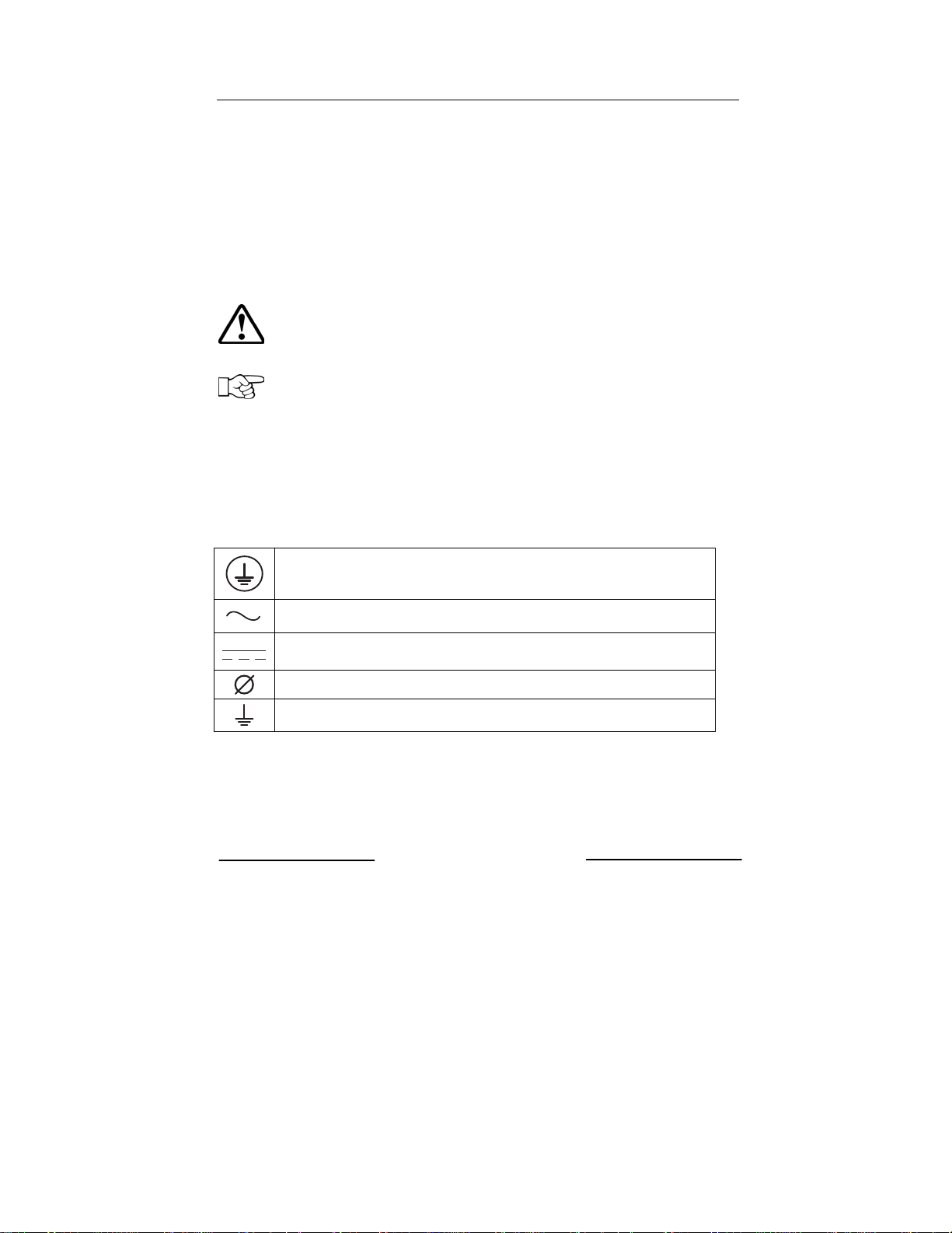
The labels utilize the following symbols:
Equipment grounding conductor (Main grounding protective earth,
PE)
Alternate Current (Ac) value
Direct Current (Dc) value
Phase
Grounding (Earth)

Installation and Operator’s Manual Page 4 of 63
(PVI-3600-OUTD-UK-F-W Rev.: 1.0)
USEFUL INFORMATION AND SAFETY STANDARD
FOREWORD
The installation of AURORA must be performed in full compliance with
national and local standards and regulations
AURORA has no internal user serviceable parts other than fuses.
For any maintenance or repair please contact the nearest authorized repair
center. Please contact your reseller if you need to know the nearest authorized
repair center.
Read and understand all the instructions contained in this manual and become
familiar with the safety symbols in the relevant paragraphs before you install
and commission the equipment
The connection to the distribution grid must be done only after receiving
approval from the distribution utility as required by national and state
interconnection regulations, and can be done only by qualified personnel.
Safety Brake the wind turbine to prevent any possibility of high voltages
appearing at the connecting cable terminations.
The AC disconnecting means must be opened before working on the Aurora
Wind inverters.
GENERAL
During inverter operation, some parts can be powered, some not properly insulated
and, in some cases, some parts can move or rotate, or some surfaces can be hot.
Unauthorized removal of the necessary protections, improper use, incorrect
installation or incorrect operation may lead to serious damage to people and
objects.
All transport, installation and start-up, as well as maintenance operations, shall be
carried out by skilled and trained personnel (all national regulations on accidents
prevention shall be complied with ! ! !).
According to these basic safety rules, qualified and trained people have skills for
the assembling, start-up and operation of the product, as well as the necessary
requirements and qualifications to perform such operations.
ASSEMBLY
Devices shall be assembled and cooled according to the specifications mentioned
in the corresponding documents.

Installation and Operator’s Manual Page 5 of 63
(PVI-3600-OUTD-UK-F-W Rev.: 1.0)
In particular, during transport and handling, parts shall not be bent and/or the
insulation distances shall not be changed. There should be no contact between
electronic parts and connection terminals.
Electrical parts must not be mechanically damaged or destroyed (potential health
risk).
ELECTRICAL CONNECTION
With the inverter powered, comply with all prevailing national regulations on
accidents prevention.
Electrical connections shall be carried out in accordance with the applicable
regulations, such as conductor sections, fuses, PE connection.
OPERATION
Systems equipped with inverters shall be provided with further control and
protective devices in compliance with the corresponding prevailing safety rules,
such as those relating to the compliance with technical equipment, accidentpreventing regulations, etc. Any calibration change shall be made using the
operational software. Once the inverter has been disconnected from the power grid,
powered parts and electrical connections shall not be touched as some capacitors
could be charged.
Comply with all corresponding marks and symbols present on each device. During
operation, make sure that all covers and doors are closed.
MAINTENANCE AND SERVICE
Comply with manufacturer’s recommendations.
SAVE ALL DOCUMENTS IN A SAFE PLACE !

Installation and Operator’s Manual Page 6 of 63
(PVI-3600-OUTD-UK-F-W Rev.: 1.0)
PVI-3600-OUTD-UK-F-W
This document applies to the above-mentioned inverters, only.
Fig. 1 - Product label information example
The identification plate present on the inverter includes the following data:
1) Manufacturer Part Number
2) Model Number
3) Serial Number
4) Production Week/Year

Installation and Operator’s Manual Page 7 of 63
(PVI-3600-OUTD-UK-F-W Rev.: 1.0)
CONTENTS:
1 FOREWORD 9
1.1 WIND ENERGY 9
2 SYSTEM DESCRIPTION 9
2.1 Main Elements of a Wind System: 10
2.2 Data Transmission and Check 12
2.3 AURORA Technical Description 12
2.4 Protective Devices 14
2.4.1 Anti-Islanding 14
2.4.2 Ground Fault 14
2.4.3 Further Protective Devices 14
2.5 System Design: 15
3 INSTALLATION 15
3.1 Package Inspection 16
3.2 Package Check List 17
3.3 Choosing Installation Location 18
3.4 Wall Mounting 19
3.5 Preliminaries to Electrical Connections 22
4 START-UP 31
5 MONITORING AND DATA TRANSMISSION 32
5.1 User’s Interface Mode 32
5.2 Available Data 34
5.2.1 Real time data 34
5.2.2 Internally Logged Data 34
5.3 LED Indicators 35
5.4 Messages and Error Codes 38
5.5 LCD Display 40
6 DATA CHECK AND COMMUNICATION 47
6.1 RS-485 serial link 47
6.2 Power Line Modem (PLM) 49
6.3 Display menù 51
6.4 Address Information 51
6.5 Manual address setting 51
6.6 Automatic setting 52
6.7 Verifying the paralleled input configuration. 52
6.8 Measurement Accuracy 54
7 TROUBLESHOOTING 56
8 TECHNICAL FEATURES 58
8.1 Input Values 58

Installation and Operator’s Manual Page 8 of 63
(PVI-3600-OUTD-UK-F-W Rev.: 1.0)
8.2 Output Values 60
8.3 Grid protection characteristics 60
8.4 General characteristics 61
8.5 Power Derating 62

Installation and Operator’s Manual Page 9 of 63
(PVI-3600-OUTD-UK-F-W Rev.: 1.0)
1 FOREWORD
This document contains a technical description of the AURORA wind inverter so
as to provide the installer and user all the necessary information about installation,
operation and use of AURORA.
1.1 WIND ENERGY
Industrialized countries (greater energy consumers) have been experimenting with
energy-saving methods and reducing pollutant levels. This may be possible
through a shrewd and rational consumption of well-known resources, and also by
looking for new forms of clean and in exhaustible energy.
Renewable sources of energy are fundamental to solving this problem. Under these
circumstances, wind energy exploitation to generate electrical energy is becoming
more and more important worldwide.
2 SYSTEM DESCRIPTION
AURORA inverter changes the wind energy into AC power which is fed to the
electrical power distribution grid.
AURORA does this conversion, also known as Dc to Ac inversion, in a very
efficient way, without using rotating parts but just static power electronic devices.
When used in parallel with the grid, the alternate current generated by the inverter
is directly fed to the domestic distribution circuit, which in turn is also connected
to the public power distribution grid.
The wind energy system can thus feed power to all the grid-connected loads, such
as lighting devices, household appliances, etc.
If the energy generated by the wind energy system is not enough, the energy
necessary to ensure the standard operation of the connected users is drawn from
the public power distribution grid. Any excess energy produced by the inverter is
exported to the grid.
According to national and local standards and regulations the produced energy can
be sold to the grid or credited to the user against future consumption.
Installation and Operator’s Manual Page 10 of 63
(PVI-3600-OUTD-UK-F-W Rev.: 1.0)
2.1 Main Elements of a Wind System:
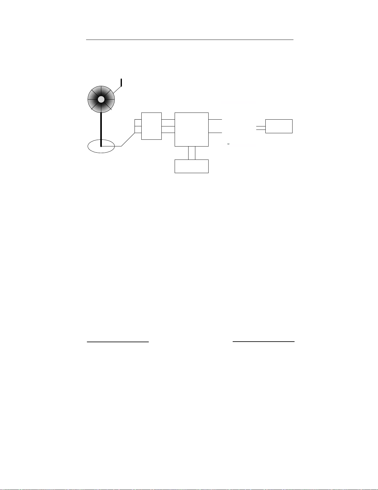
A wind system is composed of a wind turbine, a permanent magnet
generator or alternator, Wind Interface Box and Aurora Wind
inverter.
The output of wind turbine is converted from mechanical energy into
electrical energy by the permanent magnet (PM) generator. The
output of the PM generator is a variable frequency, variable voltage
waveform, commonly referred to as “wild AC”.
The output of the PM generator is feed into the Wind Interface Box.
The Wind Interface Box provides rectification and diversion load
control. The diversion load control when connected to a properly
sized resistive load provides control of the turbine output in high
wind, over-speed conditions and loss of grid which will cause the
unloading of the wind turbine. The diversion load is not a safety
brake.
The Aurora Wind inverter changes the rectified output of Wind
Interface box into useable AC which is supplied to the grid at predetermined nominal voltage and frequency. The Aurora Wind
inverter is supplied with the Wind turbine manufacturer’s model
specific power curve. The model specific power curve is used by the
Wind maximum power point tracking (MPPT) to extract the
maximum amount of energy from the turbine at a given rpm.
WARNING: The DC voltage shall not exceed 600Vdc for any reason,
so as to avoid damage to the equipment.
NOTE: A minimum DC input voltage value of 50Vdc is required to
start-up the grid connection sequence of AURORA Wind. Once
connected, AURORA will transfer to the grid the maximum power
available from the string for any DC input voltage value in the range
from 50Vdc to 530Vdc.
Installation and Operator’s Manual Page 11 of 63
(PVI-3600-OUTD-UK-F-W Rev.: 1.0)
The Aurora Wind Inverter is designed to accept only a single wind input. The
current of this input is limited to 20 Amperes.
Safety
Brake
Wind Interface
Box
Diversion Load
Fig.3 Simplified diagram of a Wind system
AC
Disconnect

Installation and Operator’s Manual Page 12 of 63
(PVI-3600-OUTD-UK-F-W Rev.: 1.0)
2.2 Data Transmission and Check
In case multiple inverters are used, they can be monitored remotely by using an
advanced communication system based on the serial interface RS485 or on the
Power Line Modem (PLM) technology. For further information, refer to the
corresponding sections of this manual.
2.3 AURORA Technical Description
Figure 4 shows a block diagram of AURORA. The main blocks are the input DcDc converters (called boosters) and the output inverter. Both the Dc-Dc converters
and the output inverter work at high switching frequency to minimize size and
weight.
This model of AURORA is transformer-less, that means that there is no galvanic
isolation between input and output. This allows an increase the inverter efficiency.
AURORA is equipped with all the protection needed to operate safely and to
comply with existing safety regulations even without an isolation transformer.

Installation and Operator’s Manual Page 13 of 63
(PVI-3600-OUTD-UK-F-W Rev.: 1.0)
Aurora Wind Inverter
High Voltage DC Bus
Grid Interface Inverter
3.6 kW
Gate Drive Board
Optoisolation
Inverter
Inverter
Embedded
Embedded
Controller
Controller
2 - line LCD Reset
Line Filter
Inverter Current Feedback
Grid Voltage Feedback
CB1
20 A
K1
To
Distribution
Panelboard
Breaker
= 400 V max.
V
oc
= 360 V nom.
V
nom
V
PMSG
min
PMG
input
= 40
Aurora Wind
Inteface Box
20 A
Load Bank
(Optional)
DC/DC Boost Converter
3.6 kW
Gate Drive Board
DC Current Feedback
Generator Voltage Feedback
Operator
Interface
Fig.4 AURORA block diagram
The block diagram shows the model AURORA PVI-3600-OUTD-UK-F-W with
its two input Dc-Dc converters. The two Dc-Dc converters are controlled in
parallel by the Wind maximum power point tracker control.
Thanks to its high efficiency and large heat-sink, AURORA offers max. power
operation over a wide ambient temperature range.
The inverter is digitally controlled by means of two independent Digital Signal
Processors (DSP), and one microprocessor.
Two single-chip independent computers maintain control in full compliance with
the electric standards relating to systems power supply and safety.
The AURORA operating system performs inter-process communication checks to
ensure the entire unit operates properly.
Installation and Operator’s Manual Page 14 of 63
(PVI-3600-OUTD-UK-F-W Rev.: 1.0)
This process ensures optimal performance levels of the whole unit, as well as a
high efficiency over the input voltage operating range and load conditions, always
in full compliance with the applicable directives, standards and regulations.
2.4 Protective Devices
2.4.1 Anti-Islanding
When the local power distribution grid fails due to a fault or when the equipment
is shut down for maintenance operations, AURORA shall be physically
disconnected under safety conditions, so as to protect the people working on the
grid, in full compliance with the applicable prevailing national standards and
regulations. To avoid any possible islanding operation, AURORA is provided with
an automatic disconnection protective system called Anti-Islanding.
The AURORA PVI-3600-OUTD-UK-F-W model is equipped with an advanced
Anti-Islanding protection certified according to the Clear Skies standard.
2.4.2 Ground Fault
The Ground fault detection identifies ground faults that are present on the DC
input conductors and the AC output conductors. An advanced ground fault
protection circuit continuously monitors the earth (ground) connection and shuts
down AURORA in case a ground fault is detected and indicates the ground fault
condition by means of a red LED on the front panel. AURORA is equipped with a
(chassis) ground screw clamp, which shall be used for connection of the plant
Protective Earth conductor (equipment grounding conductor). See section 3.5
(step 4/7) for detailed grounding instructions.
WARNING: Do not connect the Wind AURORA inverter to multiple
wind turbine inputs. The AURORA inverter is designed for connection
to a single wind turbine only.
NOTE: For detailed information on AURORA disconnection and on
malfunctioning causes, refer to the corresponding sections.
2.4.3 Further Protective Devices
AURORA is equipped with additional protections to guarantee safe operation
under all circumstances. The protections include:
Continuous monitoring of the grid voltage to ensure the frequency and
voltage values are within the proper operational limits;
Installation and Operator’s Manual Page 15 of 63
(PVI-3600-OUTD-UK-F-W Rev.: 1.0)
Control of the internal temperatures to automatically drive the speed of the
external cooling fan. This will allow the inverter to deliver the maximum
output power for ambient temperatures up +40 ° C .
The AURORA is designed for safe and reliable operation. This is made possible
by the use of redundant control circuits.
2.5 System Design:
The overall system design of a wind system is critical to successful
operation and maximizing energy production.
Step 1:
The first step is determining the wind resource at a location is a site
survey and possible wind monitoring.
Step 2:
The second step is purchasing a pre-designed wind system that
includes the Aurora Wind inverter with a turbine specific power
curve.
A wind turbine model specific power curve is pre-programmed into
the Aurora Wind Inverter. The wind power curve is used by the
Aurora Wind Maximum power point tracking algorithm to product
the maximum amount of available energy.
Step 3:
The third step a proper installation of the entire wind energy system.
3 INSTALLATION
WARNING: The electrical installation of AURORA must be made in
accordance with the electrical standards prescribed by the local
regulations and the National electrical standards.

Installation and Operator’s Manual Page 16 of 63
(PVI-3600-OUTD-UK-F-W Rev.: 1.0)
WARNING: The connection of AURORA to the electrical distribution
grid must be performed only after receiving authorization from the utility
that operates the grid.
3.1 Package Inspection
NOTE: The distributor presented your AURORA WIND Inverter to the
delivering carrier securely packed and in perfect condition. Upon
acceptance of the package from the distributor the delivering carrier
assumes responsibility for its safe arrival to you. Regardless of the
attention paid by carrier in handling it, sometimes the package and its
contents might be damaged.
Please, carry out the following checks:
Examine the shipping box for any visible damage: punctures, dents or any
other signs of possible internal damage;
Describe any damage or shortage on the receiving documents and have the
carrier sign their full name;
Open the shipping box and inspect the contents for internal damage. While
unpacking, be careful not to discard any equipment, parts or manuals. If any
damage is detected, call the delivering carrier to determine the appropriate
action. They may require an inspection. Save all shipping material for the
inspector to see!
If the inspection reveals damage to the inverter call your supplier, or
authorized distributor. They will determine if the equipment should be
returned for repair. They will also provide instructions on how to get the
equipment repaired;
It is your responsibility to file a claim with the delivery carrier. Failure to
properly file a claim for shipping damages may void warranty service for any
physical damages later reported for repair;
Save the AURORA original packaging, as it will have to be used in case the
equipment has to be shipped out for repairs, or the responsible inspector
requires it.
Installation and Operator’s Manual Page 17 of 63
(PVI-3600-OUTD-UK-F-W Rev.: 1.0)
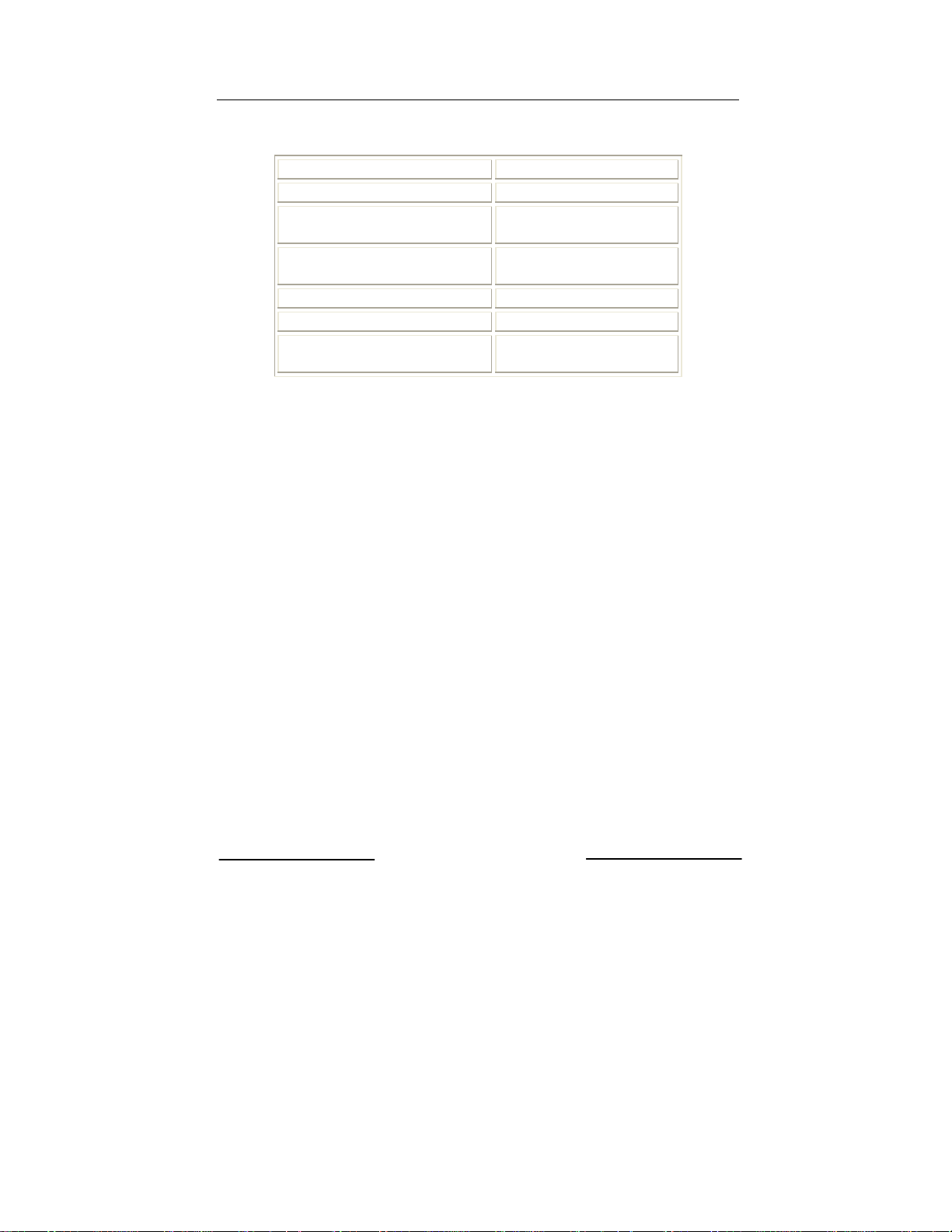
3.2 Package Check List
Description Quantity (No.)
Wind Inverter 1
Bag with 4 screws, 4 blocks and
1 Tap wrench Torx TX20
One mounting reference
drawing
One copy of this manual 1
One certificate of warranty 1
CD-Rom with communication
software
1
1
1
Installation and Operator’s Manual Page 18 of 63
(PVI-3600-OUTD-UK-F-W Rev.: 1.0)
3.3 Choosing Installation Location
The location for the installation of AURORA should be selected in accordance to
the following recommendations:
AURORA should be placed at a suitable height from ground to allow easy
reading of the front display and the status LEDs.
Leave enough room around the unit to allow easy installation and
maintenance.
Choose a location sheltered from sun radiation and able to provide some
ventilation. Avoid locations where air cannot freely circulate around the
unit, or directly exposed to the sun.
The mounting location should also allow space for the Wind Interface Box
and the Diversion load.
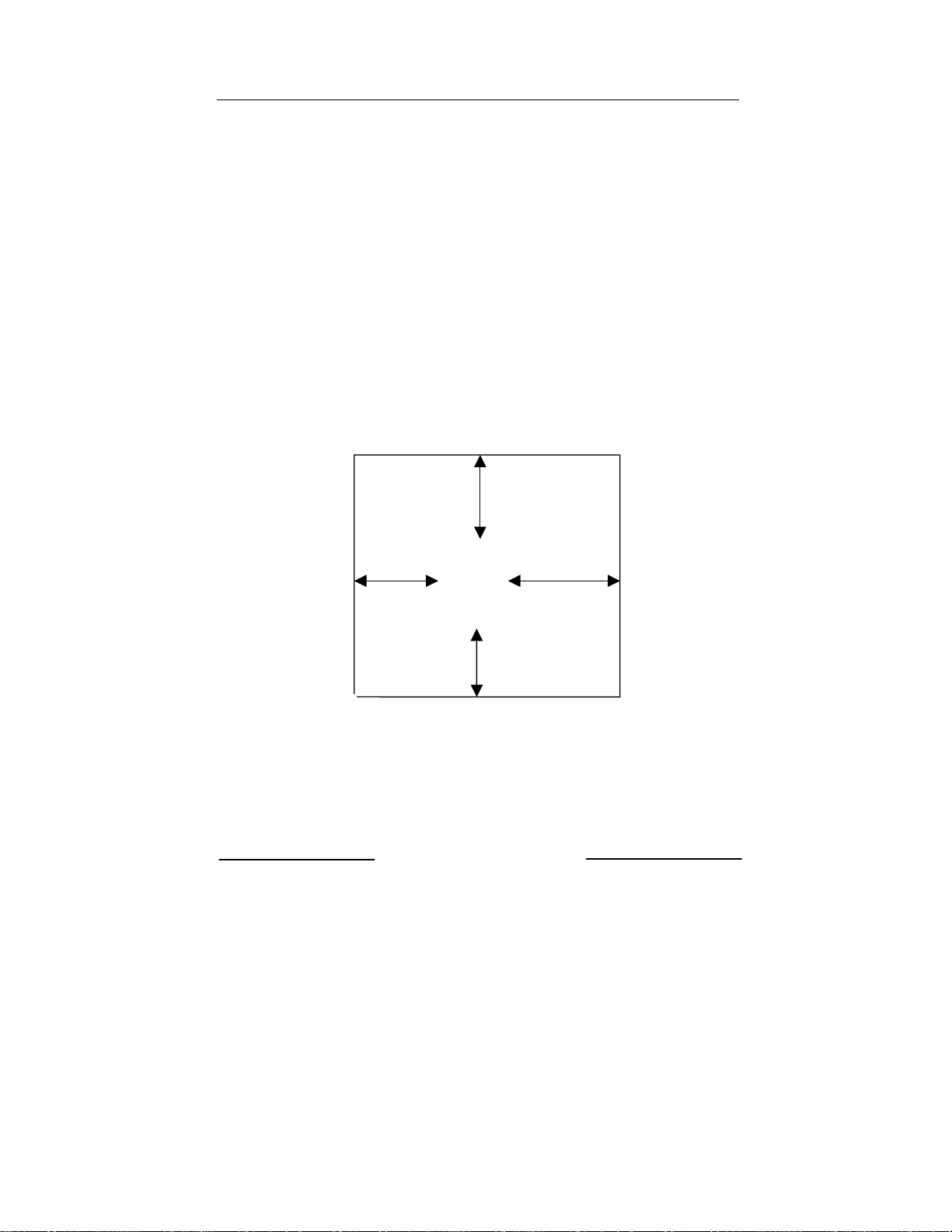
Minimum clearance requirements on the sides easily access the side cover
and to obtain the best performance of the unit are as per the following
figure:
500 mm (18”)
>100 mm
(4”)
Fig.5 Minimum clearance requirements
>300 mm
(12”)
500 mm (18”)

Installation and Operator’s Manual Page 19 of 63
(PVI-3600-OUTD-UK-F-W Rev.: 1.0)
3.4 Wall Mounting
AURORA should be mounted in a vertical position as shown in figure 7.
NOTE: AURORA ratings are based on a vertical mounting position.
Although it is possible to mount AURORA in a tilted position, the
thermal performance in that case may be de-rated. In any case avoid
mounting AURORA with the front plate rotated, always make sure that
the fins of the front heat-sink are vertical.
To facilitate wall mounting a reference drawing is provided in the package (Fig.6).
Use the drawing to locate the holes on the wall. A set of standard expansion
stainless steel screws is included in the package for use in mounting the AURORA
to a masonry wall. In case of different materials make sure to select the proper
mounting hardware. Always use stainless steel mounting hardware, if the supplied
hardware is not used.
The clearance hole in the mount bracket is 8 mm.
Fig.6 Wall mounting diagram
 Loading...