

Page 1

AURORA AUDIO INTERNATIONAL
6850 Vineland Avenue, Unit E
North Hollywood, CA 91605
Phone: 818 358 4328 Fax: 818 358 4320
Email: [email protected]
Website: www.auroraaudio.net
10 Channel 2 Output Aurora Sidecar Handbook
Page Index:
Page 2 – Introduction
Page 3 – Configuring the Power Supply (Read this first!)
Page 4 – Aurora Sidecar Block Diagram
Page 5 – Connecting To The Aurora Sidecar
Page 6 – The DI input And Correct Gain Structure
Page 7 – The Four-Band Equalizer
Page 8 – Bus Sends, Phase, and Phantom Power Controls
Page 9 – Mixing To The Stereo Mix Busses
Page 10 – International dBFS Levels
Page 11 – Aurora Sidecar Maintenance (Removing Modules)
Page 12 – Aurora Sidecar Maintenance (Channel item details)
Page 13 – Aurora Sidecar Channel Wiring Diagram
Page 14 – Bus and Stereo O/P wiring diagram
Page 15– Specifications
Page 16 – Warranty details
Page 1
Page 2

10 Channel 2 Output Aurora Sidecar Manual
Introduction:
“Congratulations on your purchase of our 10 channel 2 output Aurora Sidecar! I am
confident that you will find that its many features and great Class A discrete vintage
sound will help you to make great recordings.
The Aurora Sidecar is a large and professional piece of equipment. As such, it will need
to be maintained. The better it is maintained, the better service you will have for a
longer period of time.
Read through this manual to familiarize yourself with the controls and optimal operating
procedures.”
-Geoff Tanner
Page 2
Page 3

Connecting Aurora Sidecar To Power Source:
The sidecar uses an
external linear dc
power supply and the
correct input voltage
must be selected before
connecting the power
supply to ac power.
The red input voltage selector should be positioned up (115v setting) for 100v – 120v ac
supplies and positioned down (230v setting) for 220v – 240v ac supplies.
It is very important to ensure the correct input voltage is selected. If 230v is applied
when the switch is selected to 115v, the primary windings of the transformer will be
damaged and the fuse will blow. Replacing the fuse will not repair the damaged
windings and the warranty on the power supply will be voided as there are warnings
printed on the front and reverse of the power supply case and emphasized here.
Linear power supplies use a large transformer that will radiate a small electro-magnetic
field outside the steel case. Always position the power supply away from any sensitive
audio transformers (that you might have in nearby microphone preamplifiers) and do not
put anything on top of the power supply that would prevent the heat from the internal
heatsink escaping.
Always use a 3 pin ac (IEC) cable and plug to provide the power supply with a safety
ground connection. Never use any form of ground lift.
The power supply has both input and output fuses to give maximum protection to both
the power supply and the sidecar. It would be very unusual for either the 24v or 48v
labeled fuses to blow and this would most likely be caused by a power cable being
crushed by a door or wheeling something very heavy over it. Always replace the fuse
with one of the same value, as printed below the fuse holder.
Page 3
Page 4
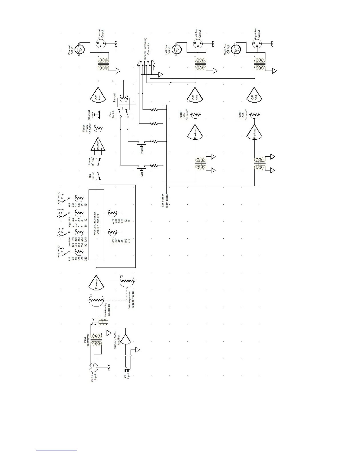
Aurora Sidecar Block Diagram:
Page 4
Page 5
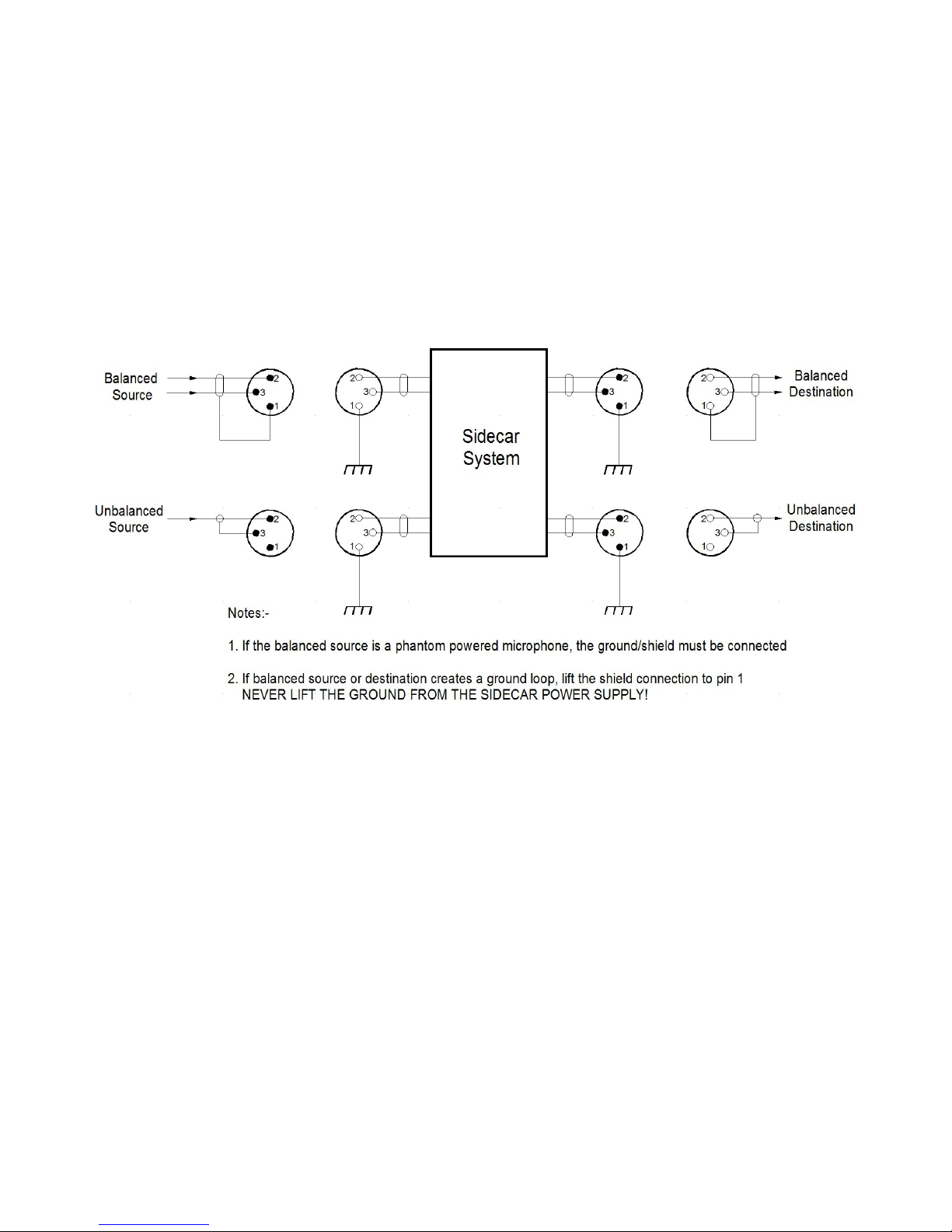
Connecting Your Equipment To The Aurora Sidecar:
As you can see from the block diagram, all rear panel inputs and outputs are XLR
connections and are transformer balanced and floating. It is important to take advantage
of the transformer's isolation from grounds as the transformer could not care less
whether it connected to a balanced or unbalanced source or destination!
Balanced cables and connections are configured the normal way with pin 2 = hot phase,
pin 3 = cold phase and pin 1 = ground. Pin 1 should not be any part of an audio signal
and, if connecting to an unbalanced source or destination, connect the signal to pin 2 and
the shield to pin 3, as shown below.
As detailed above, ground loops may occur if the studio equipment is sourced from
multiple power outlets (which may even be on different phases or lacking the earth
connection altogether), sourced from multiple power distribution strips (all plugged into
one another) or from double insulated devices that use a 2 pin power connection.
If all the studio devices are at the same ground potential, there is no potential difference
between them so no ground loop, caused by equalizing currents between the devices,
will be created. It is better to keep all the equipment at the same ground potential so that
the lifting of pin 1's in the XLR's will not be necessary.
Page 5
Page 6
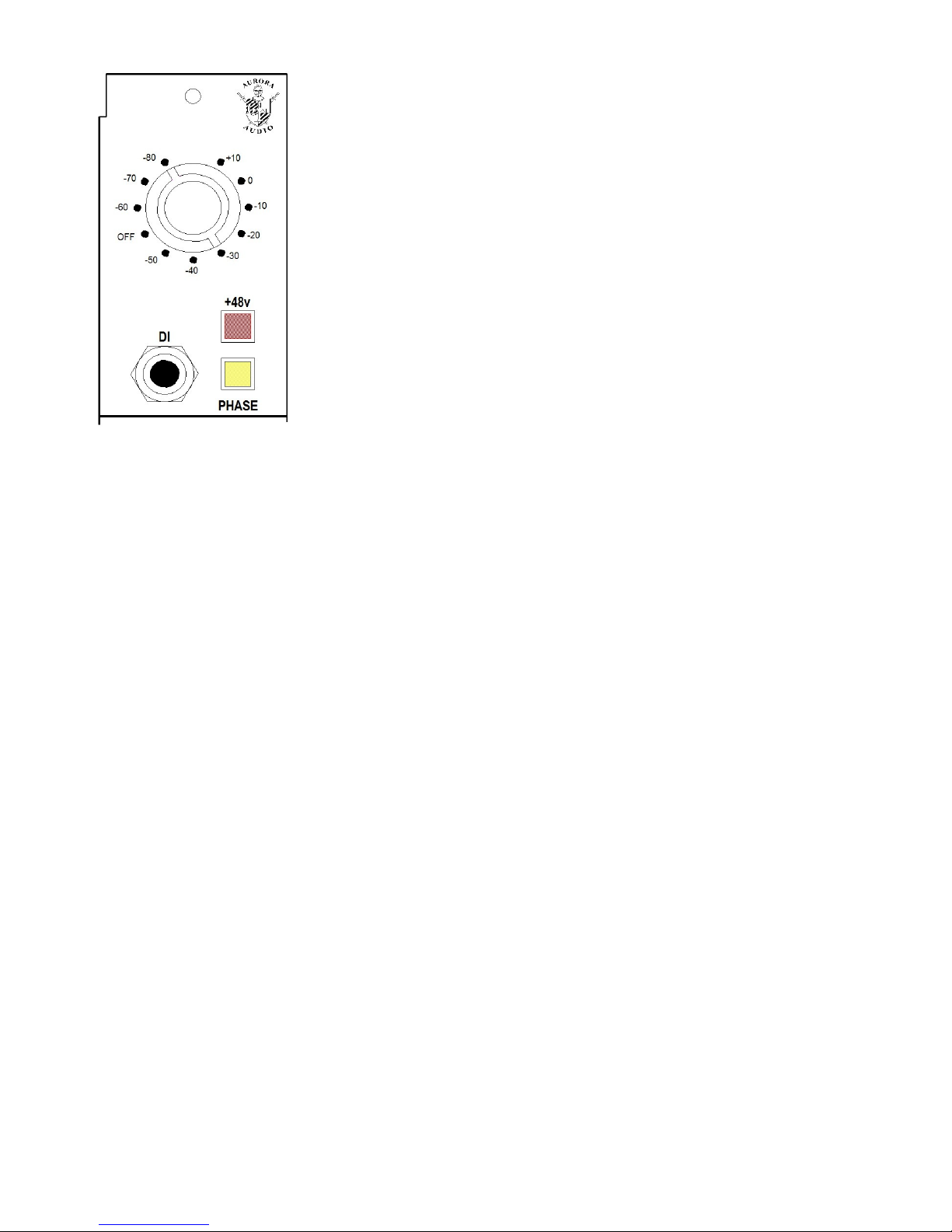
The D.I Input On The Front Of The Channel Modules:
If you plug a mono source, like a guitar, bass, or synthesizer into
the 1/4” jack on an Aurora Sidecar channel, it will cut the XLR
source to the channel and select this DI source automatically.
The XLR source can remain connected, but it will not be in
circuit until the jack is removed from the DI input.
The input impedance to the DI input is 10MΩ, that is ten million
ohms. To the device plugged into that input it may just as well be
an open circuit, like the guitar cable is unplugged and laying on
the floor, because the pick up will so lightly loaded that every
single nuance of sound gathered by that pick-up will be caught
and amplified by the Aurora Sidecar channel module.
The channel has a gain range of 90dB with signals from +10dBu to -80dBu and has over
26dB headroom on correctly set gains.
Setting Up The Channel For The Correct Gain Structure:
At the top of each channel is an illuminated VU meter that reads the post fader channel
output level. With the channel fader set to 0dB and the equalizer switched out, the red
gain knob can be turned clockwise from the +10dB position while a microphone or DI
input is connected and spoken/played at the anticipated level. Continue to turn the red
gain knob until the VU meter needle is just above or below the red 0VU to +3VU
region.
The Penny + Giles (P&G) fader has 10dB gain at the top of its travel to fine tune any
levels that fall between the 10dB gain steps. The channel gain is now correctly set for
that source.
For maximum headroom, this procedure of matching gain to input level is traditionally
seen as a proper way to set levels. To overdrive the channel, increase the gain on the red
gain knob and lower the fader to desired recording levels. This procedure will not hurt
the circuitry of the Aurora Sidecar preamp.
Page 6
Page 7
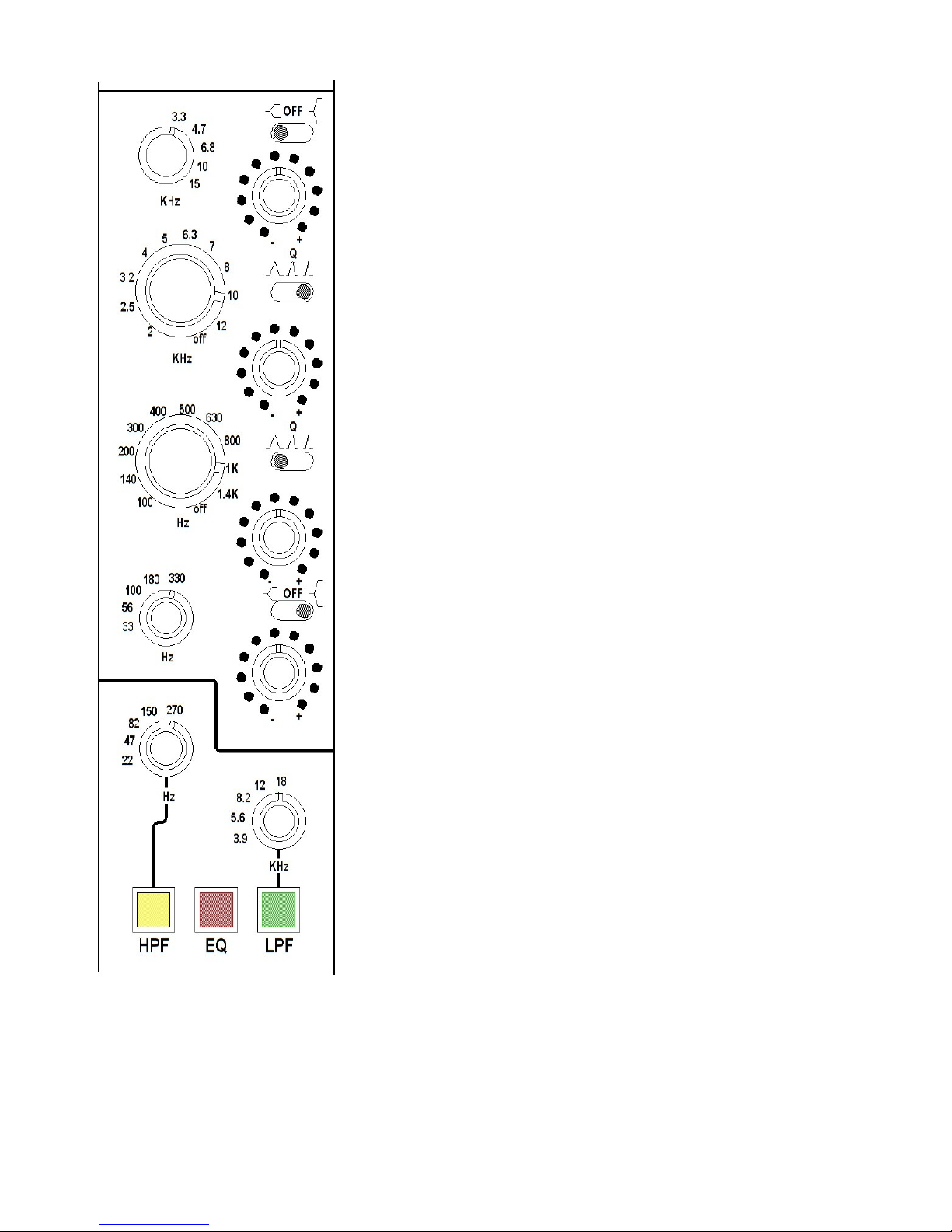
The Four-Band Equalizer:
The four-band equalizer, like the rest of the Aurora Sidecar,
is all discrete transistor Class A circuitry.
The equalizer is selected by pressing the red “EQ” button
at the bottom of the channel. With the pots in the center
detent position the gain should not change significantly
when the equalizer is selected or deselected.
Starting from the high frequency control at the top, there is
a three position switch that varies the boost and cut to
allow very fine tuning of the EQ. With the switch to the left
the variance is +/- 6dB and with it to the right the variance
is +/-16dB.
The high and low mid frequency controls underneath have
a three position switch that provides three alternatives of
“Q” (bandwidth). The mid controls in the widest “Q” can
have almost 20dB boost/cut.
The low frequency control is similar to the high frequency
in that two choices of boost/cut can be selected, +/-6dB and
+/-16dB. Note that there is considerable overlap in
frequency choices between the HF and LF and the two mid
frequency controls.
To select either high pass or low pass filter, the red “EQ”
button must be selected, then press either yellow or green
button to select the 18dB per octave filter required.
Page 7
Page 8
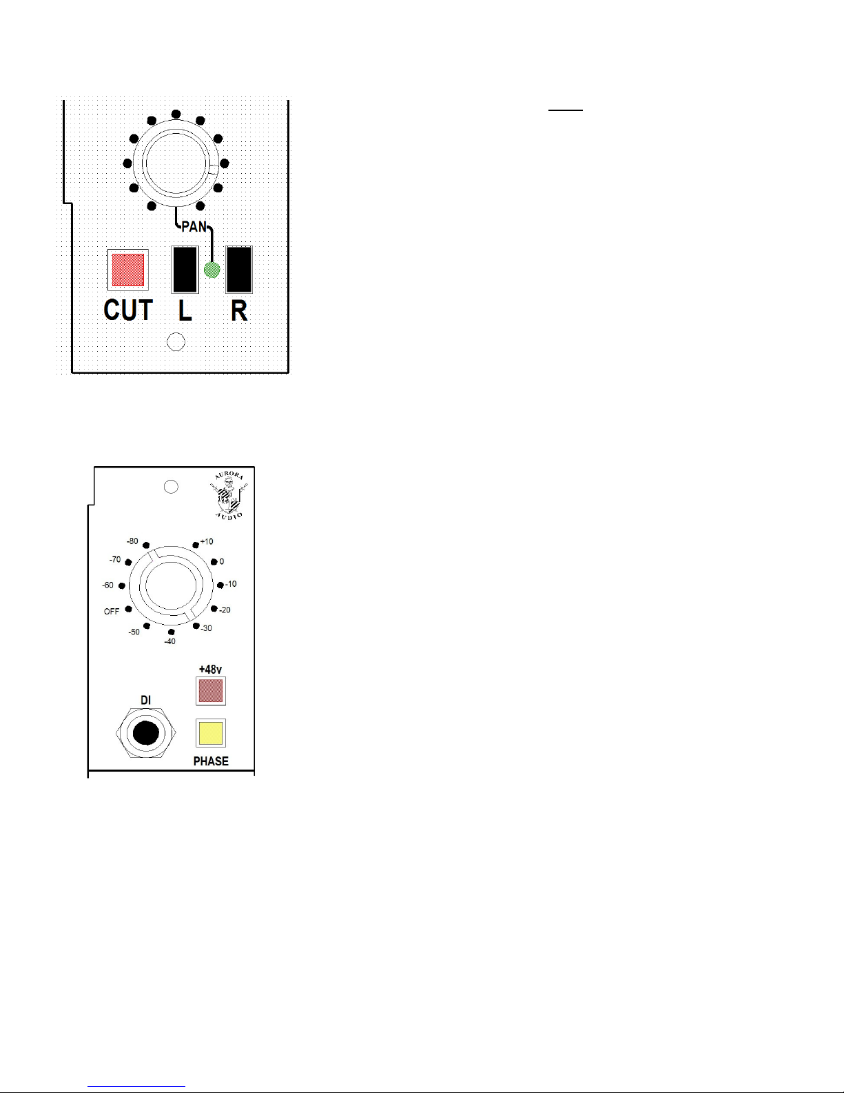
Bus Sends, Pan-Pot Controls, And Cut Switch:
The pan-pot is only in line when both Left and Right bus
assign buttons are pressed. The green “Pan” LED will
illuminate to confirm that the pan-pot is in line and the pan
control can now be turned to place the sound in the required
stereo image.
Either the Left and Right bus assign buttons can be pressed
individually to positively connect to either mix bus-bar.
The “Cut” control mutes both the bus assigns and the
channel outputs completely from the audio path.
Phase And Phantom Power Controls:
The yellow “Phase” button works on both the channel output
and the bus assigns and flips the phase 180º when pressed.
The red “+48v” button switches on the phantom power for
condenser microphones.
Page 8
Page 9

Mixing To The Stereo Mix Busses:
The channel signals are sent, via the bus assign buttons, to mix resistors that voltage sum
the channel signals onto the left and right mix busses. The mix bus uses the traditional
process of using a transformer to couple the bus signal into the mix amp preamplifier
stage. This gives the Aurora Sidecar the extra “iron” in the mix circuit path to produce a
sound unobtainable with a virtual earth, current mix into an IC operational amplifier.
The mix amp preamplifier drives the P&G conductive plastic output faders, which feed
the Aurora Audio classic output stage and transformer. A VU meter is wired across the
stereo output XLR's to provide level indication.
On the subject of VU meters, both the channel output and stereo output VU meters read
+4dBu for 0VU on the meter. This is a voltage of 1.228v ac and you will see a small
hole below each VU meter that gives access to a trim potentiomer that allows the user to
finely adjust the 0VU reference point.
Page 9
Page 10

International dBFS Levels:
On a technical note, 0dBm (an old telephone and early broadcast system of reference) is
the voltage required to dissipate 1mW into 600 ohms = 0.775v ac. 0dBu (also 0.775v ac)
just means that the impedance of the circuit is not specified. These, set in granite actual
voltage levels, rather go out of the window when referred to dBFS figures associated
with digital converters! (dBFS = deciBels Relative to Full Scale... i.e the clipping point
of the system)
There is no single standard for setting where the 0dBFS point is...!!!
For example...
1. EBU R68 is used in most European countries, specifying +18 dBu at 0 dBFS
2. In Europe, the EBU recommend that -18 dBFS equates to the Alignment Level
3. European & UK calibration for Post & Film is −18 dBFS = 0 VU
4. UK broadcasters, Alignment Level is taken as 0 dBu (PPM4 or -4VU)
5. US installations use +24 dBu for 0 dBFS
6. The American SMPTE standard defines -20 dBFS as the Alignment Level
7. In Japan, France and some other countries, converters may be calibrated for +22
dBu at 0 dBFS.
8. BBC spec: −18 dBFS = PPM "4" = 0 dBu
9. German ARD & studio PPM +6 dBu = −10 (−9) dBFS. +16 (+15)dBu = 0 dBFS.
No VU.
10.Belgium VRT: 0dB (VRT Ref.) = +6dBu ; -9dBFS = 0dB (VRT Ref.) ; 0dBFS =
+15dBu.
0VU on the Aurora Sidecar VU meters is +4dBu (1.228v ac) and normally -18dBFS on
the meters of the digital converters.
Page 10
Page 11

Aurora Sidecar Maintenance:
The channel section of the Aurora Sidecar is modular and modules can be easily
removed and replaced.....
To remove the module, undo the two
captive thrumb-screws and use them to
pull the channel module from its
connector and out of the Sidecar frame.
To replace the module, hold it by the
captive thumb-screws and insert the top,
longer side, into the upper steel guide
rail.
Gently lower the module and engage the lower part of the module into the lower steel
guide rail, lowering the module until the front face of the module is almost level with the
neighboring channels. Move the channel module gently from side to side until you feel
its connector engaging with the connector in the sidecar frame. Then push fully down.
Tighten the captive thumb-screws to secure the channel module firmly into the Sidecar
frame.
Under no circumstances should the module be allowed to drop into the frame as it
will most likely damage the module connectors!
The Aurora Sidecar channel is allsteel construction and the rear of the
module forms a shield to prevent
cross-talk between adjacent
channels. The open frame
construction also allows heat from
the Class A circuitry to circulate and
dissipate.
The combination of steel thumbscrews and steel full-length guide
rails hold the modules very firmly
in position and the Sidecar can be
moved with the modules in situ.
Page 11
Page 12
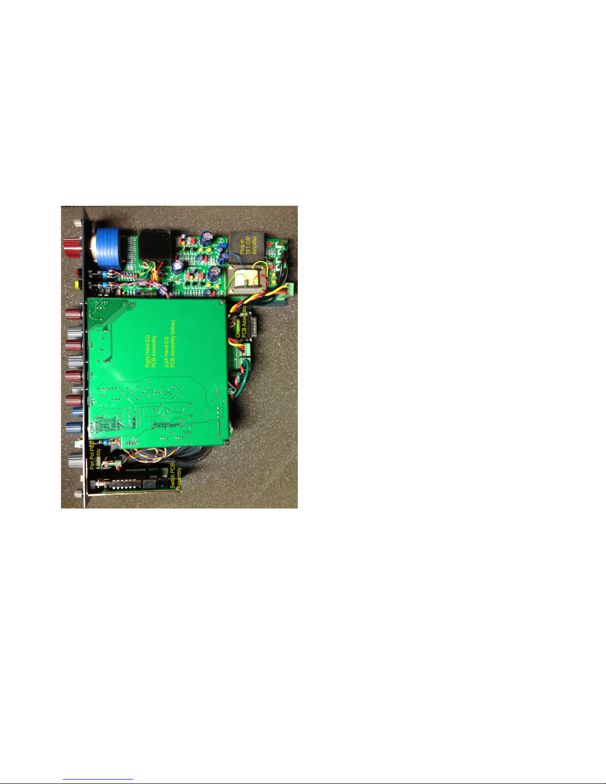
The Aurora Sidecar is robustly built out of all steel frame components and well
engineered electronic circuitry.
The Aurora Sidecar can operate with channels removed but the bus level will rise
marginally as there will be less loading on the mix busses. An increase in 0.5dB with
one module removed and 1.0dB with two modules removed shows the small margin
involved.
Aurora Audio, or your local distributor, can provide replacement channel modules in
return for the damaged or broken channel. For the benefit of experienced technicians,
this photo shows the layout of the Sidecar channel.
At the top of the module is the Pre-amplifier
assembly. This comprises the input and
output transformers, the plug-in TF1 Output
amplifier, and the discrete circuitry.
It can be removed by pulling off the knobs,
removing the nut on the gain switch and DI
jack socket, and removing the M3 screw,
nut, and spacer retaining the rear of the
PCB.
Unplugging the various connections allows
the PCB to be removed. Make notes of
which connector went to where.
The plug-in TF1 output amplifier is retained
by an M3 nut below the PCB. When
replacing, ensure all five gold pins are
aligned with their sockets.
To check its operation, the voltage on the yellow and blue pins of the output transformer
should be approximately 1.5v dc if functioning correctly.
The equalizer circuit boards are removed as a single assembly by pulling off the knobs
and removing the nuts beneath. Make a note of the connector wiring before unplugging.
If in doubt, use the diagram on the following page to confirm which connector goes
where.
We recommend the use of Electrolube EML 200F switch cleaner/lubricator spray for
the cleaning and servicing of switches on the channel module.
Page 12
Page 13
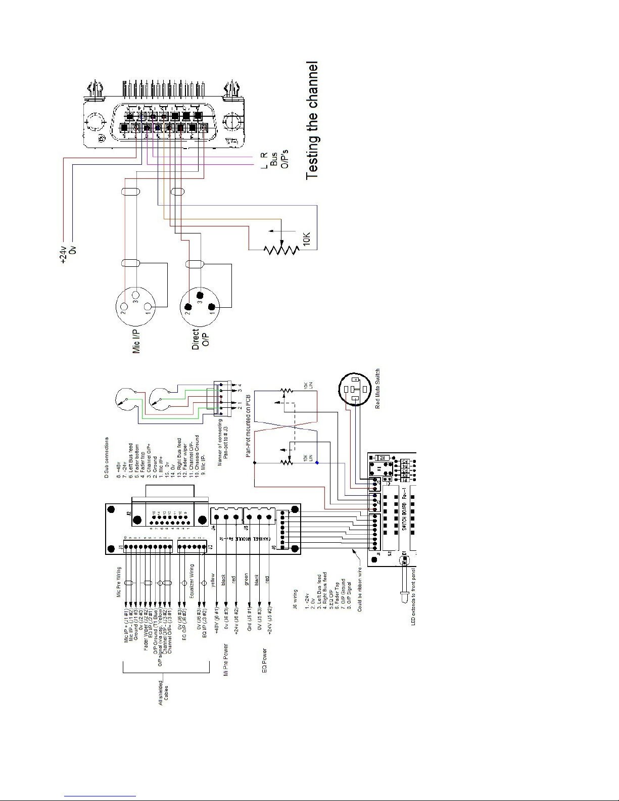
Aurora Sidecar Channel Wiring Diagram:
Page 13
Page 14
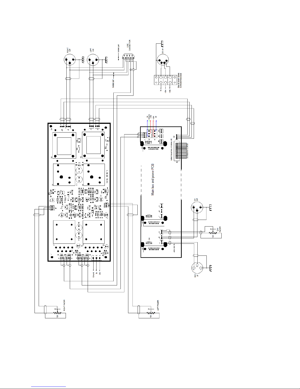
Aurora Sidecar Bus and Stereo O/P Wiring:
Page 14
Page 15

Specifications:
Channels
Gain :- -10dB to +80dB on the input sensitivity switch plus
another 10dB in the fader.
Input Impedance :- 1.2Kohm (XLR I/P), 10Mohm (DI I/P)
Output Impedance :- < 50 ohms balanced
VU Meter range :- Standard VU points from -20VU to +3VU where
0VU = +4dBu = 1.228 vac. Front panel trimpot to
align the 0VU point.
Input headroom :- 26dB
Outputs :-
Gain :- Stereo outputs are unity gain
Output Impedance :- < 50 ohms balanced
Frequency response :-< +/- 0.5dB at 20Hz and 20KHz ref. 0dBu @ 1KHz
Noise :- < -75dB all channels assigned to a bus.
< -85dB channel O/P noise @ unity gain
< -45dB channel O/P noise @ +80dB gain (EIN = -125dB)
Crosstalk :- < -70dB @ 1KHz
Headroom :- Maximum outputs all > +26dBu
Distortion :- < 0.075% @ 1KHz
Page 15
Page 16

Warranty: ONE YEAR PARTS AND LABOR LIMITED WARRANTY
Aurora Audio International warrants this Aurora Sidecar unit against defects in
workmanship for a period of one year and parts for a period of one year from receipt by
the original end user. This warranty shall not apply to damage resulting from misuse
including water damage, in-transit damage, fire damage, improper maintenance,
dropping the unit and operation or storage outside the environmental specification for
the product.
Only skilled technicians should repair the Aurora Sidecar. Please contact Aurora Audio
for technical advice. Aurora Audio is committed to helping you get best use out of the
Aurora Sidecar.
ROHS Directives
The RoHS Directive stands for "the restriction of the use of certain
hazardous substances in electrical and electronic equipment". This
Directive bans the placing on the EU market of new electrical and
electronic equipment containing more than agreed levels of lead,
cadmium, mercury, hexavalent chromium, polybrominated biphenyl
(PBB) and polybrominated diphenyl ether (PBDE) flame retardants.
The restrictions took effect in the E.U from 1st July 2006.
It is very important that the owner of any piece of equipment that contains even
microscopic amounts of the listed hazardous substances (in relation to the weight of
the unit) realize that the responsibility of its disposal rests with them. The unit
should not just be thrown away at the end of its lifetime, whether that's 10, 20 or 30
years hence.
Please contact us at the address below and Aurora Audio will provide the necessary
information for proper disposal.
Aurora Audio International
6850 Vineland Avenue, Unit E
North Hollywood, CA 91605
Page 16
Page 17

Addendum #1 :- Using Channel and Output Pre-fade insertions.
An optional feature for the Audio Sidecar, which can be factory or distributor retro
fitted, is line level and balance pre fade insertions for the channels and 2T bus outputs.
These involve fitting a new, hinged, rear panel that contains the insert circuit boards. A
new bottom panel is needed to give clearance to the rear panel as it swings down, and a
special bus circuit board is used with connections to the insertion circuit boards. This
information is only relevant if a non-insert Aurora Sidecar needs to be retro converted to
the insert option.
The pre fade insertion consists of two 1/4” TRS jack sockets, both carrying a balanced
line level signal, with the upper jack the pre fade insertion send and the lower jack the
pre fade insertion return.
Between the two TRS jack sockets is a toggle switch which, if set to the left, totally
bypasses the insert circuitry (the TRS jacks are non functioning) while, if set to the right,
engages the insertion circuitry. This enables a user to switch in or out a device
permanently connected to the insertion jacks and, in the very rare likelihood of a
component failure, allows the circuitry to be totally bypassed.
Above and below the input and output XLR connectors are small holes allowing access
to trim potentiometers that adjust the gain of the amplifiers connected to the TRS jack
sockets. The upper trimpot sets the insertion send level while the lower trimpot sets the
insertion return level.
Connecting the TRS jacks to unbalanced devices :-
All audio paths entering or exiting the TRS jack sockets are electronically balanced and
unity gain. If the channel input gain is set at 0dB, the channel fader set at 0dB and the
input signal is +4dBu, the insert send and return levels will be +4dBu as will the channel
output.
Balanced circuitry is used in professional audio because of the noise canceling it
provides on long cable runs, especially cables that run alongside ac power cables whose
magnetic fields can be induced into the audio cable. Unbalanced cabling does not
provide this protection.
When connecting unbalanced equipment, special care has to be taken to avoid ground
loops because ground is part of the signal path.
Page 18

Important... always use stereo TRS jack plugs with the TRS panel
mounted jack sockets...
Never plug mono jack plugs into the TRS panel mounted jack sockets.
For best results, always use balanced devices and wiring.
The pre fade insertion return circuitry is electronically balanced and acts similar to a
transformer, accepting balanced or unbalanced signals to the tip and ring contacts of the
panel mounted jack sockets without signal loss or degradation.
Alternatively, the cable mounted TRS plug can be wired unbalanced with hot on the tip
and shield to the shield connection. Don't wire anything to the ring contact of the plug.
The pre fade insertion send circuitry is also electronically balanced and only intended to
drive a balanced load. It has protection against shorting an output to ground but this is
not recommended as a long term application of a short circuit could damage the
amplifier.
Again, the cable mounted TRS plug can be wired unbalanced with hot on the tip and
shield to the shield connection. Don't wire anything to the ring contact of the plug.
Checking alignment levels :-
Channel path -
1. Switch the insertion selector switch to the bypass position.
2. Align the channel gain switch to the 0dB position and adjust the fader such that
the channel is unity gain from the input XLR to the output XLR. An input level of
+4dBu enables the VU meters to be simultaneously checked that they read 0VU.
The fader knob should be very close to the 0dB point on its scale.
3. Switch the insertion selector switch to the in position and plug a TRS stereo jack
plug cable (to male XLR) into the pre-fade insertion send jack socket.
4. Adjust the upper trim potentiometer to give a +4dBu signal out of the pre-fade
insertion jack to the male cable XLR.
5. Plug a TRS stereo jack plug cable (to female XLR) into the pre-fade insertion
return jack socket.
6. Applying a +4dBu input balanced signal to that cable XLR, adjust the lower trim
potentiometer to achieve a +4dBu level coming out of the channel output XLR.
7. If both TRS jack to XLR cables are removed, the Sidecar should still be unity gain
from channel input XLR to channel output XLR.
Page 19
Stereo Bus Output Path :-
This is very similar to the channel path procedure. The +4dBu signal present on the
channel input and output should be assigned to one bus at a time. Do not press both Left
and Right bus buttons at once as this engages the pan pot and can introduce level
variation due to the 3dB insertion loss. Do the procedure to the Left bus first then
disengage the Left send button and engage the Right send button.
Left Output Path -
1. Switch the insertion selector switch to the bypass position.
2. Send the +4dBu signal from the channel to the Left output. Ensure that the output
fader is at maximum (0dB) and check that the 2T Output level is +4dBu.
3. Switch the insertion selector switch to the in position and plug a TRS stereo jack
plug cable (to male XLR) into the pre-fade insertion send jack socket.
4. Adjust the upper trim potentiometer to give a +4dBu signal out of the pre-fade
insertion jack to the male cable XLR.
5. Plug a TRS stereo jack plug cable (to female XLR) into the pre-fade insertion
return jack socket.
6. Applying a +4dBu input signal to that cable XLR, adjust the lower trim
potentiometer to achieve a +4dBu level coming out of the Stereo Output XLR.
7. If both TRS jack to XLR cables are removed, the Sidecar should still be unity gain
from channel input XLR to Stereo output left XLR.
The Right Output path is a repeat of the Left Output Path detailed above.
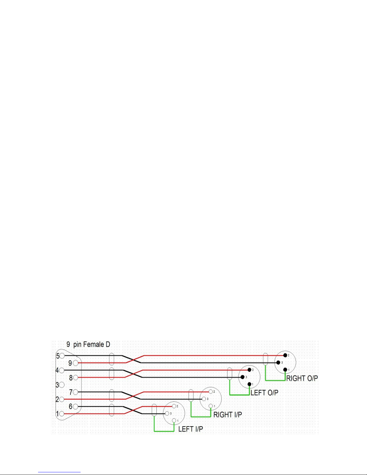
Below is shown the wiring to the 9 pin D-Sub connector :-
Page 20
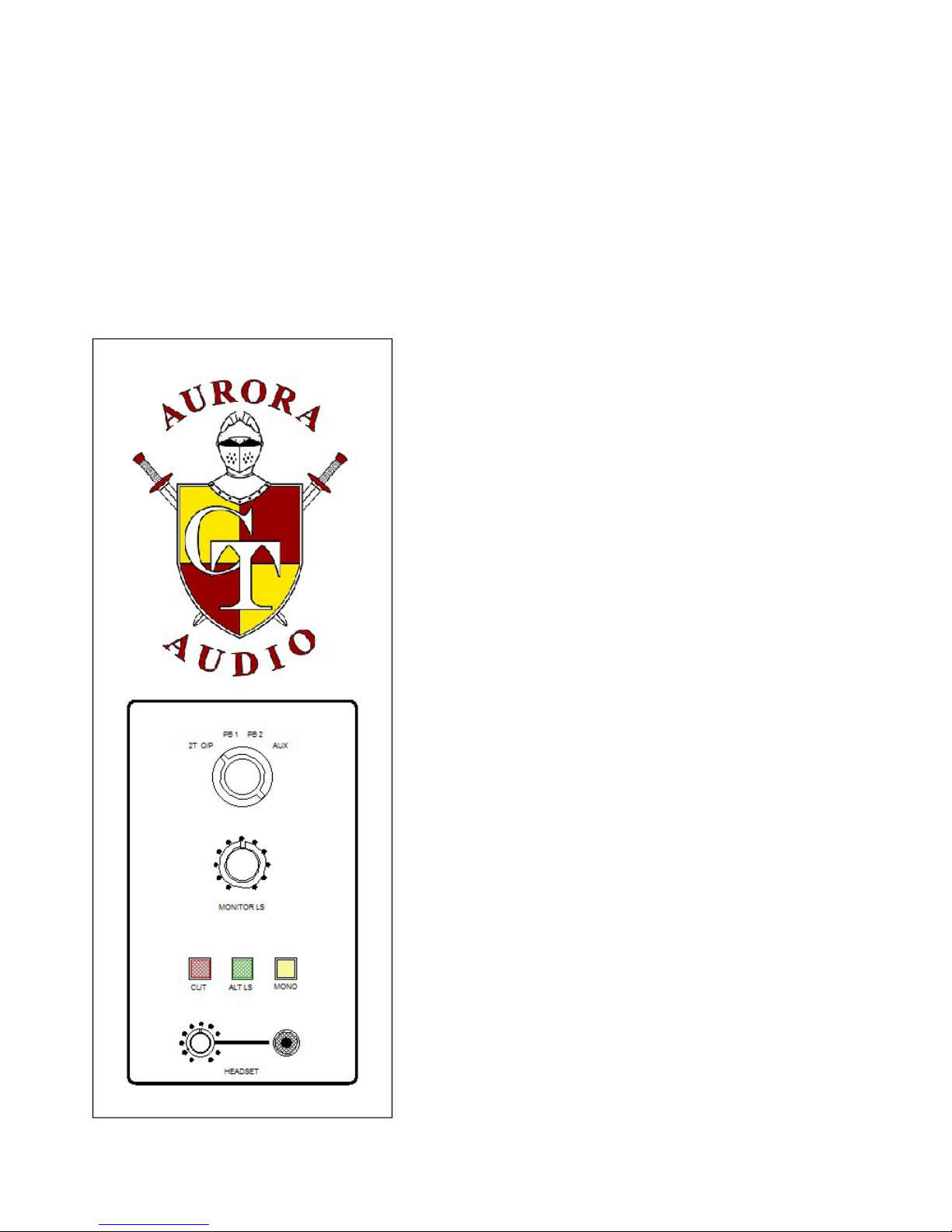
Addendum #2 :- Using the Monitor Panel.
An optional feature for the Audio Sidecar, which can be factory or distributor retro
fitted, is the new monitor panel that turns the Sidecar into a small Console.
These involve fitting a new, hinged, rear panel that contains the insert circuit boards and
the XLRs for Playback Inputs and Monitor Outputs. This option is only available with
the Channel and Bus Pre fade insertion option so basic Sidecars must be converted to
adopt both options.
The source selector can switch between four stereo
sources and the 2T VU meters, the Monitor outputs
and Headset outputs follow the the source selected.
The Sources are 2T O/P, Playback 1, Playback 2 and
Aux which, because its input is a TRS jack socket,
can also serve as an input from a smartphone or
similar device.
While the first three inputs are +4dBu
balanced/floating inputs for 0VU on the VU meters
and a +10dBu monitor output (i.e. 6dBu level “in
hand”), the Aux input is unbalanced (actually it's
quazi balanced) and has 6dB additional gain for low
output devices (i.e 12dB level “in hand”).
The Monitor level control is detented to provide a
degree of repetition of favorite output level.
The Headset output is independent of the Monitor
Level control enabling the monitor speakers to be
turned off and monitoring be done via the headset
output. Alternatively the headset output could be
used as a cue source for the artist being recorded.
As headphones come in a wide range of impedances
the driver amplifiers are two 25 watt output devices
that enable the output signal to swing high enough
for high impedance headphones. At the lower
impedance end, protection is provided to prevent
damage to both headphones and users ears!
Page 21
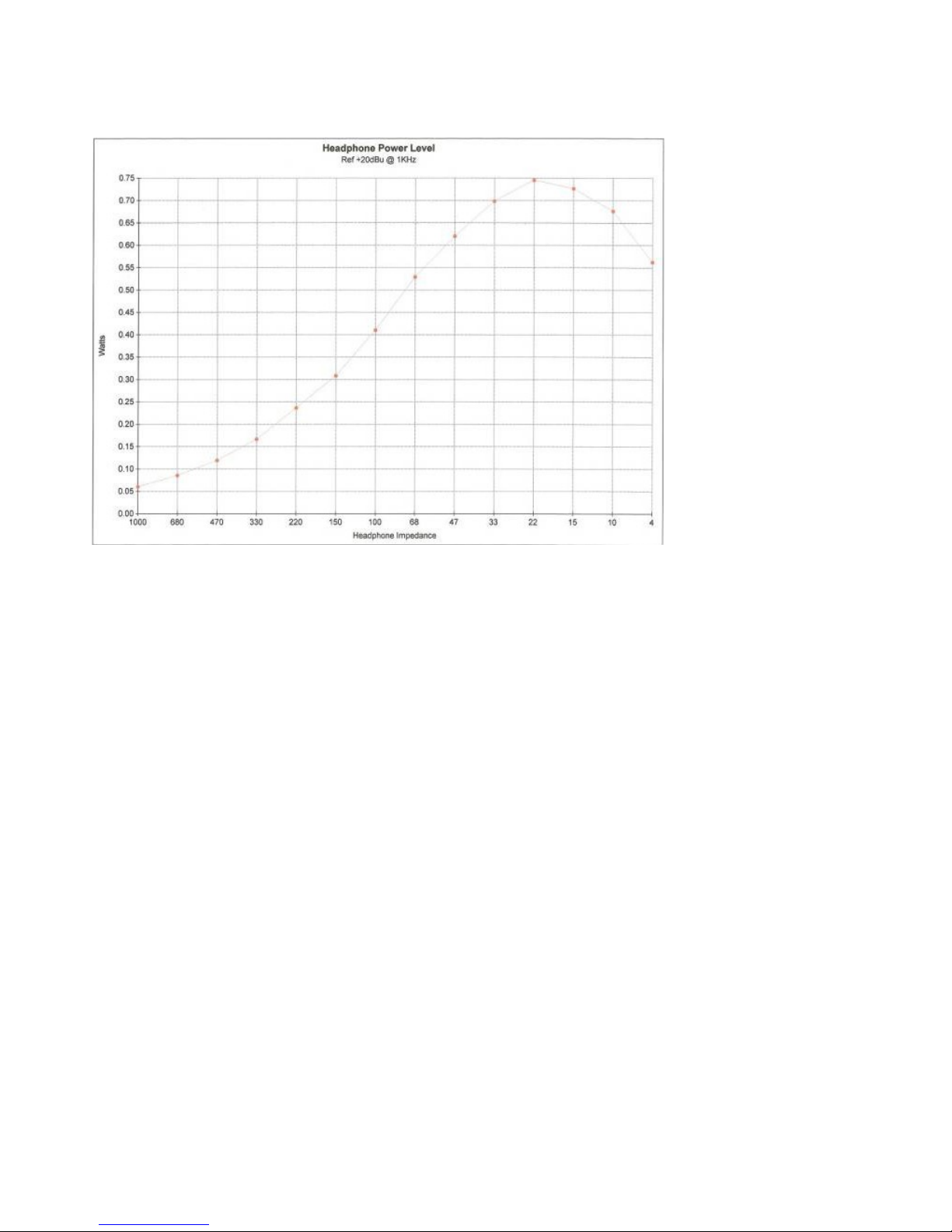
See graph below for output levels versus headphone impedance.
Three illumination push buttons are provided for monitor options :-
1. Cut (Red switch) fully mutes both stereo paths so no signal reaches the monitor
speakers.
2. Alt LS (Green switch) switches between two sets of monitor outputs.
3. Mono (Yellow switch) combines the two stereo signals such that both left and
right outputs are identical.
 Loading...