

Page 1
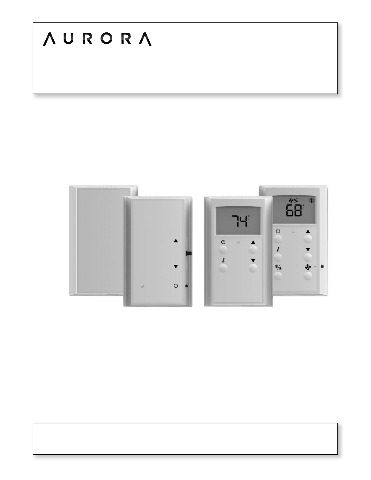
Aurora Universal Protocol Converter (UPC)
ZS Zone Sensors
Installation Guide
Aurora UPC ZS Zone Sensors Installation Guide
IG1582EW 04/14
Page 2

Page 3

Aurora UPC ZS Zone Sensors Installation Guide
Table of Contents
What are ZS Sensors? ........................................................................................................... 1!
Rnet Configuration ............................................................................................................................................... 2!
Specifications ....................................................................................................................................................... 3!
To address a ZS Sensor ......................................................................................................... 5!
Wiring and mounting a ZS Sensor ......................................................................................... 6!
Power requirements ............................................................................................................................................ 6!
Rnet wiring specifications .................................................................................................................................. 7!
To wire and mount a ZS Sensor ......................................................................................................................... 8!
To communicate through the local access port ................................................................... 10!
To set up a Local Access connection in the WebCTRL® for OEMs interface ........................................... 10!
Troubleshooting .................................................................................................................. 12!
ZS Pro or ZS Pro-F ............................................................................................................................................. 12!
To format a ZS Sensor ...................................................................................................................................... 13!
Page 4

Page 5
1
Aurora UPC ZS Zone Sensors Installation Guide
ZS Sensors are thermistor-based temperature sensors that may optionally sense humidity, CO2, or VOC. ZS
Sensors are wired to the Rnet of the Aurora UPC Controller.
The following table shows the 4 ZS Sensor models and their features.
Sensor
Features
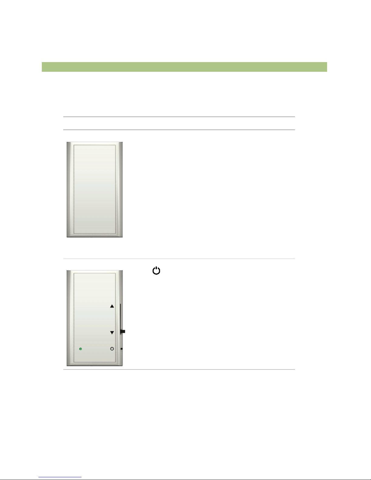
ZS Standard
• Local access port
• No user control
ZS Plus
• Slide potentiometer to make the zone warmer or cooler
• button to override the schedule and put the zone in an
occupied state, or force the zone to an unoccupied state
• Green LED to indicate occupied state
• Local access port
What are ZS Sensors?
Page 6
2
Aurora UPC ZS Zone Sensors Installation Guide
Sensor
Features
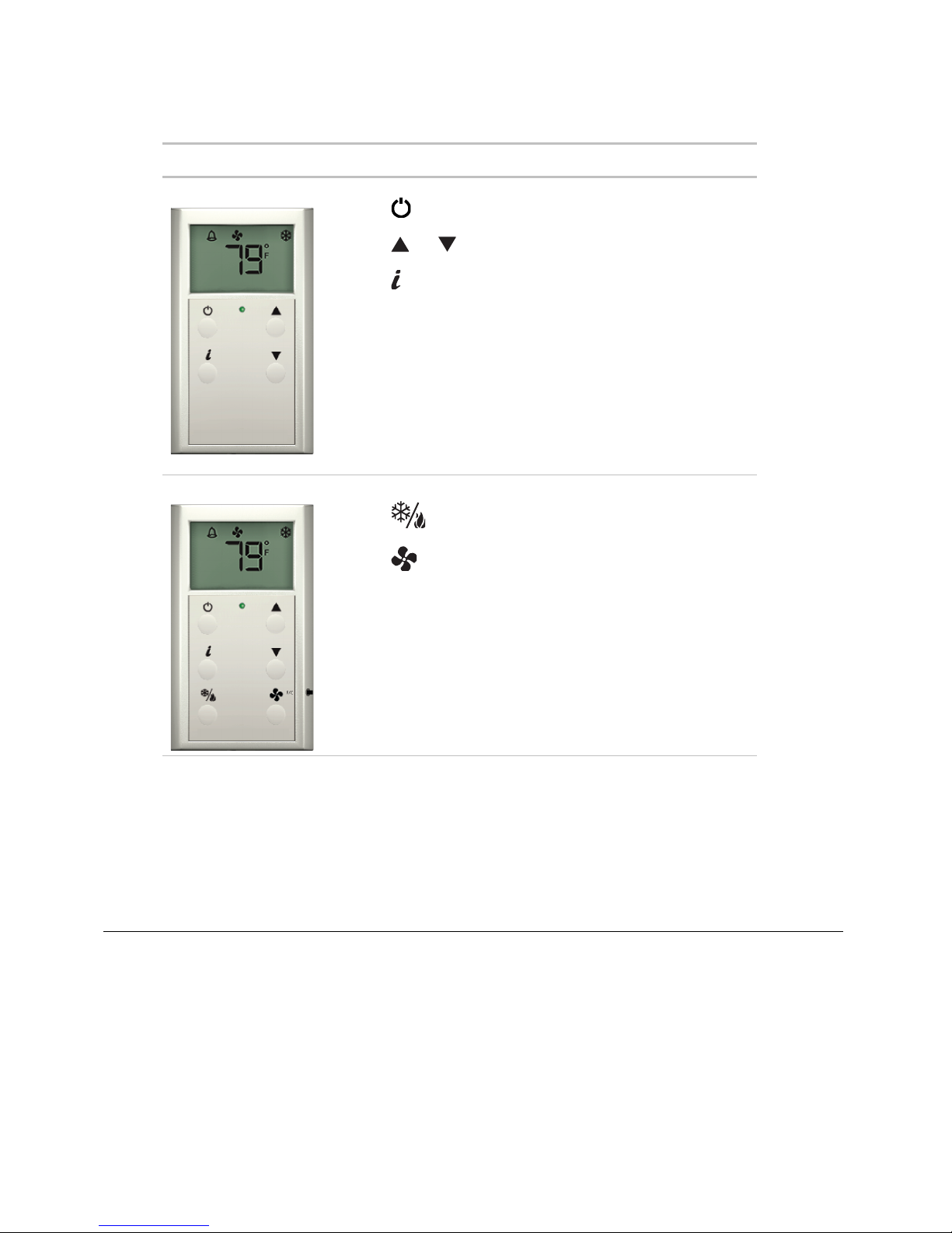
ZS Pro
• LCD display
• button to override the schedule and put the zone in an
occupied state, or force the zone to an unoccupied state
• and buttons to change any editable property, such as
the setpoint temperature
• button to cycle through information defined in the control
program
• Green LED to indicate occupied state
• Local access port
ZS Pro-F
All of the ZS Pro's features plus:
• button to turn on heating, cooling, or fan only, or set to
auto control.
• button to adjust fan speed (not used)
• F/C button to set temperatures to Fahrenheit or Celsius
To configure the control program for the desired user interaction with the sensor, see the ZS Sensor Application
Guide.
For basic user instructions, see the ZS Sensor User Guide.
!
Rnet Configuration
An Rnet can consist of the following devices wired in a daisy-chain or star configuration:
• Up to 15 ZS Sensors
• Up to 2 BACview® devices
NOTES
• Although an Rnet can have 15 ZS Sensors, you can have no more than 5 sensors per control program.
• You cannot have RS sensors and ZS sensors on the same Rnet.
Page 7

3
Aurora UPC ZS Zone Sensors Installation Guide
!
Specifications
Sensing element
range and accuracy
Temperature only
Range:
Accuracy:
32 to 122°F (0 to 50°C)
±0.35°F (0.2°C)
Temperature if humidity
is included
Range:
Accuracy:
50 to 104°F (10 to 40°C)
0.5°F (0.3°C)
Options:
Humidity
Range:
Accuracy:
10 to 90%
2% typical
CO2
Range:
Accuracy:
0 to 2000 PPM
±75 PPM typical
VOC
Range:
Accuracy:
0 to 2000 ppm
1 PPM
Power requirements
Temperature only
ZS Standard or ZS Plus:
ZS Pro or Pro-F:
12 Vdc @ 6 mA
12 Vdc @ 7 mA
Temperature with humidity
ZS Standard or ZS Plus:
ZS Pro or Pro-F:
12 Vdc @ 7 mA
12 Vdc @ 8 mA
Temperature with humidity
and VOC - All models
12 Vdc @ 60 mA
Temperature with humidity
and CO2 - All models
12 Vdc @ 15 mA (idle) to
190 mA (CO2 measurement cycle)
Temperature and CO2 -
All models
12 Vdc @ 14 mA (idle) to
189 mA (CO2 measurement cycle)
Power supply
The 4-conductor Rnet cable from a controller supplies +12 Vdc @ 210
mA. For additional power, use an external power supply. Use the above
power requirements to calculate the size of the external power supply.
Communication
115 kbps
Local access
port
For local access to start up and troubleshoot the system
Environmental
operating range
-4 to 122°F (-20 to 50°C), 10 to 90% relative humidity, non-condensing
Mounting
Standard 4x2-in. electrical box using the 6-32 x 1/2" mounting screws
provided
Page 8

4
Aurora UPC ZS Zone Sensors Installation Guide
Overall dimensions
Temperature sensor
or temperature with
humidity sensor
Sensor with CO2 or VOC
Width:
Height:
Depth:
Width:
Height:
Depth:
3 in. (7.62 cm)
4-13/16 in. (12.22 cm)
13/16 in. (2.01 cm)
2-7/8 in. (7.3 cm)
4-13/16 in. (12.22 cm)
1-1/4 in. (3.18 cm)
Listed by
FCC Part 15-Subpart B-Class A, CE
!
Page 9
5
Aurora UPC ZS Zone Sensors Installation Guide
Each ZS Sensor on an Rnet must have a unique address, but addresses do not have to be sequential.
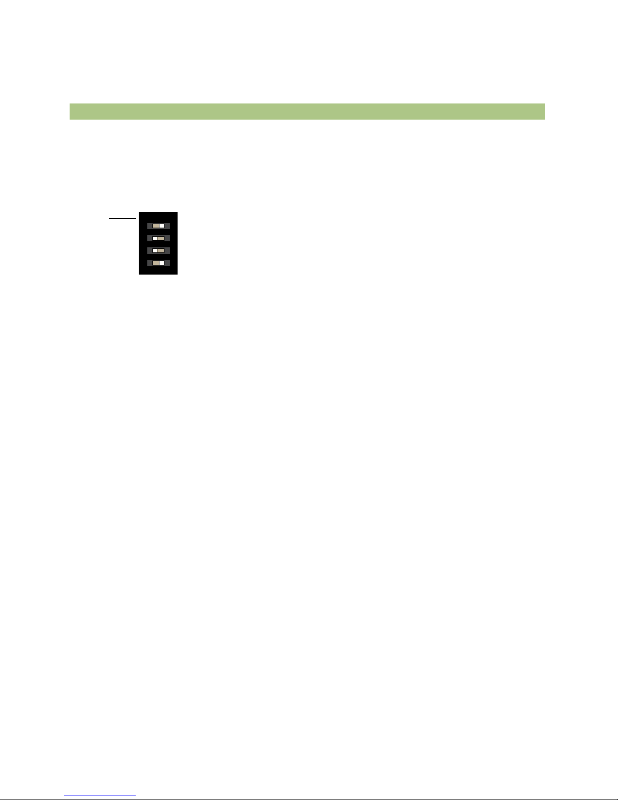
Use the DIP switches on the back of the ZS Sensor to set an address from 0 to 14. (0 is factory default.) Each DIP
switch has the value shown in the figure below. Turn on as many DIP switches as you need so that their total value
equals the address.
DIP
Switch
value
1
ON
2
4
8
1 2 3 4
EXAMPLE DIP switches 1 and 4 above are on. Their values (1 + 8) total 9, so the sensor's address is 9.
!
To address a ZS Sensor
Page 10

6
Aurora UPC ZS Zone Sensors Installation Guide
The Rnet communicates at a rate of 115 kbps and should be wired in a daisy-chain, star, or hybrid configuration.
!
Power requirements
Power requirements
Temperature only
ZS Standard or ZS Plus:
ZS Pro or Pro-F:
12 Vdc @ 6 mA
12 Vdc @ 7 mA
Temperature with humidity
ZS Standard or ZS Plus:
ZS Pro or Pro-F:
12 Vdc @ 7 mA
12 Vdc @ 8 mA
Temperature with humidity
and VOC - All models
12 Vdc @ 60 mA
Temperature with humidity
and CO2 - All models
12 Vdc @ 15 mA (idle) to
190 mA (CO2 measurement cycle)
Power supply
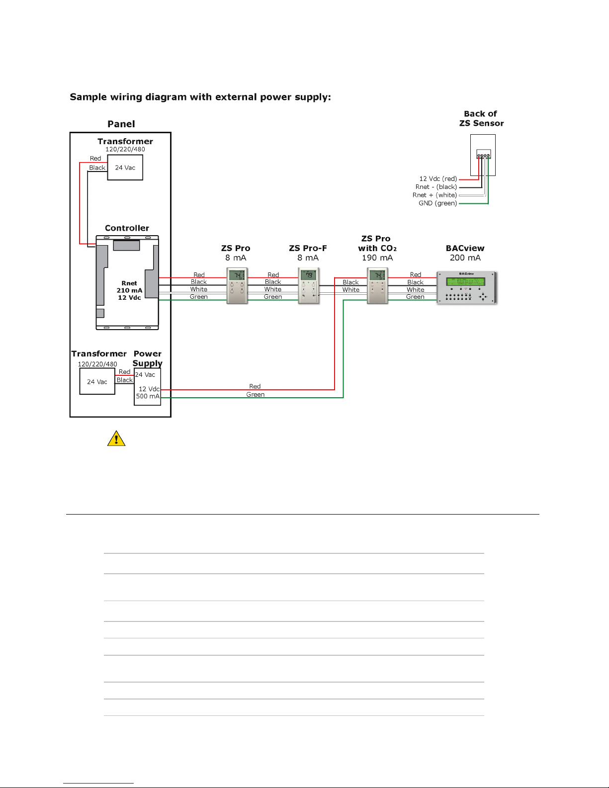
The 4-conductor Rnet cable from a controller supplies +12 Vdc @ 210
mA. For additional power, use an external power supply. Use the above
power requirements to calculate the size of the external power supply.
The controller and the external power supply must share a common
ground.
Wiring and mounting a ZS Sensor
Page 11
7
Aurora UPC ZS Zone Sensors Installation Guide
CAUTION Do not share power between controller's power and external 12 Vdc unless both devices are half
wave.
!
Rnet wiring specifications
NOTE Use the specified type of wire and cable for maximum signal integrity.
Description
4 conductor, shielded or unshielded, CMP, plenum rated cable
Conductor
22 AWG (7x0096) bare copper if Rnet has only sensors
18 AWG (7x0152) bare copper if Rnet has a BACview® device
Maximum length
500 feet (152 meters)
Insulation
Low-smoke PVC (or equivalent)
Color Code
Black, white, green, red
Shielding
If shielded, Aluminum/Mylar shield (100% coverage) with TC drain
wire, terminated at controller
UL temperature rating
32–167°F (0–75°C)
Voltage
300 Vac, power limited
Page 12
8
Aurora UPC ZS Zone Sensors Installation Guide
Listing
UL: NEC CL2P, or better
!
To wire and mount a ZS Sensor
PREREQUISITE The Rnet cable is wired to the controller. The shield wire and the ground wire should be inserted
into the controller's GND terminal.
1 Turn off the controller's power.
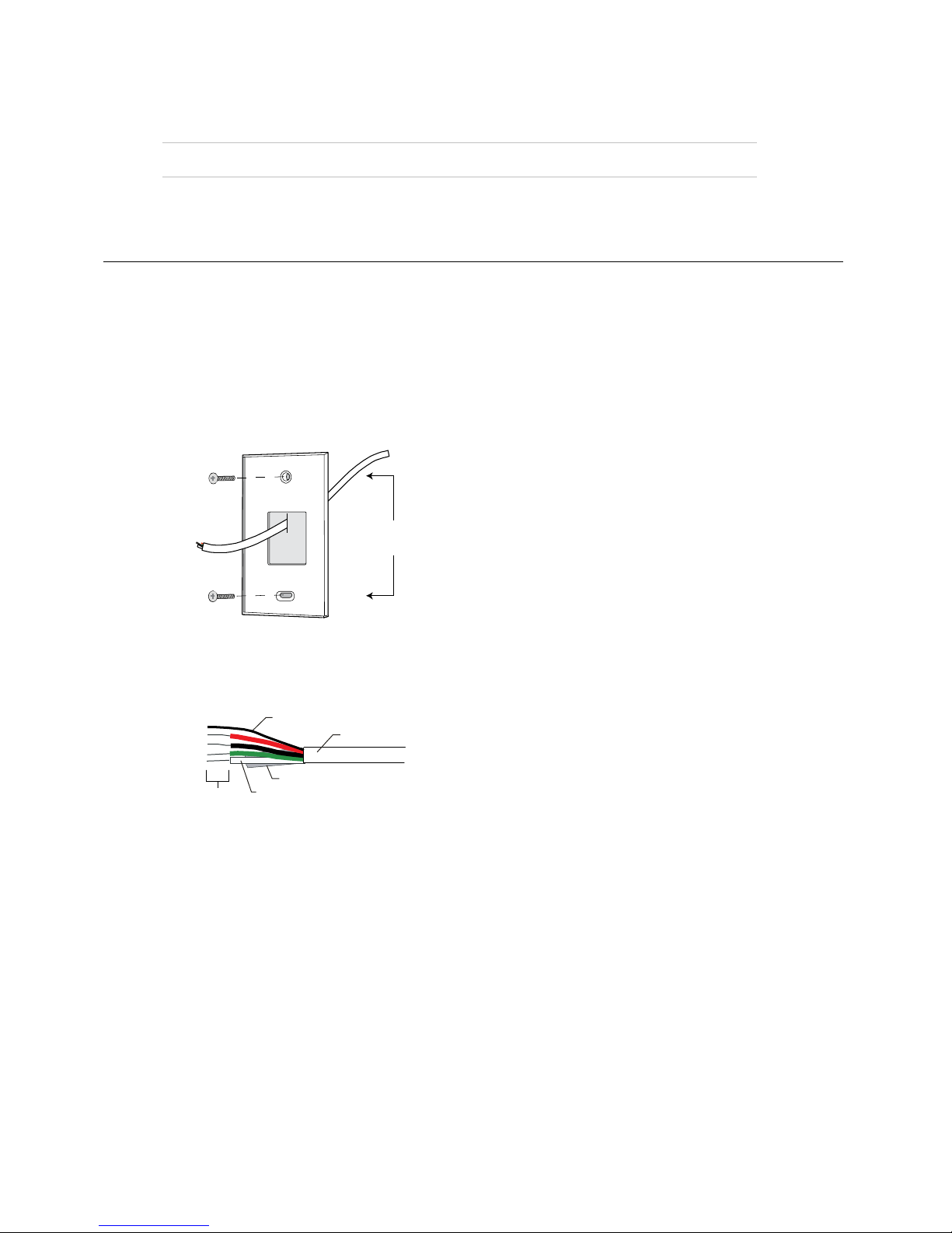
2 Pull the backplate off the ZS Sensor. You may need to turn the setscrews in the bottom of the sensor
clockwise until you can remove the backplate.
3 Pull the Rnet communication cable through the slit in the insulated backing material.
3.30 in.
(8.38 cm)
4 Use 2 screws to mount the backplate to the wall or outlet box.
5 Partially cut, then bend and pull off the outer jacket of the Rnet cable(s). Do not nick the inner insulation.
Inner insulation
Outer jacket
Foil shield
.25 in.
(.6 cm)
Shield wire
6 Strip about .25 inch (.6 cm) of the inner insulation from each wire.
7 If wiring 1 cable to the ZS Sensor, cut the shield wire off at the outer jacket, then wrap the cable with tape at
the outer jacket to cover the end of the shield wire.
If wiring 2 cables in a daisy-chain configuration, twist together the shield wires, then wrap the shield wires
with tape.
Page 13
9
Aurora UPC ZS Zone Sensors Installation Guide
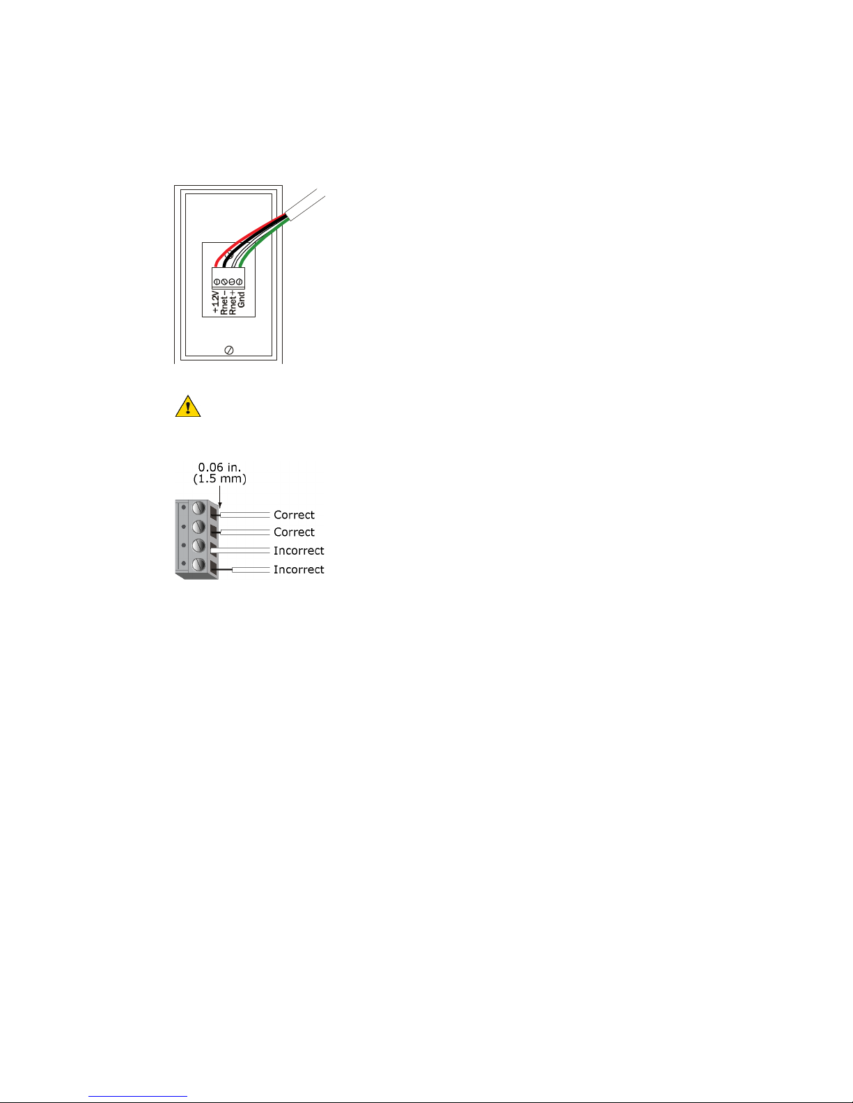
8 Insert the other 4 wires into the ZS Sensor's screw terminal connector. If wiring 2 cables, insert like-colored
wires into each terminal.
Recommended wiring scheme:
Connect
this wire...
Red
Black
White
Green
To this
terminal...
+12V
Rnet-
Rnet+
Gnd
CAUTION Allow no more than 0.06 inch (1.5 mm) bare communication wire to protrude. If bare
communication wire contacts the cable's foil shield, shield wire, or a metal surface other than the terminal
block, the device may not communicate correctly.
9 Attach the sensor's cover and circuit board to the mounted backplate, inserting the top first.
10 Turn the setscrews one full turn counterclockwise so that the cover cannot be removed.
11 Turn on the controller's power.
NOTE Use the same polarity throughout the Rnet.
!
Page 14
10
Aurora UPC ZS Zone Sensors Installation Guide
You can connect to the Local Access port of the ZS Sensor to perform test and balance or to make changes to any
device on the network.
PREREQUISITES
• A computer with a USB port
• A USB Link Kit
CAUTION If multiple controllers share power but polarity was not maintained when they were wired, the
difference between the controller's ground and the computer's AC power ground could damage the USB Link Kit
and the controller. If you are not sure of the wiring polarity, use a USB isolator between the computer and the USB
Link Kit. Purchase a USB isolator online from a third-party manufacturer.
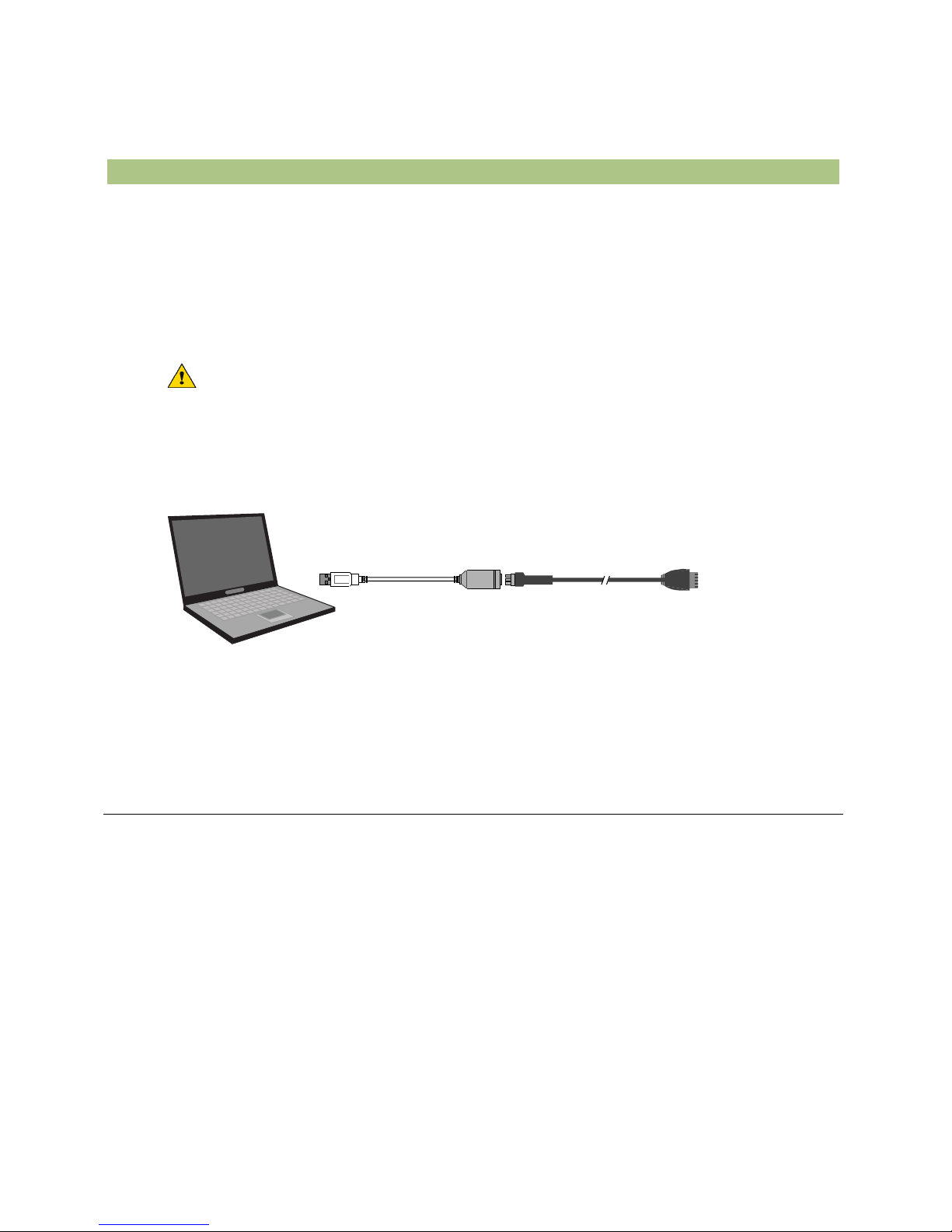
Connect the USB Link Kit to the computer and to the ZS Sensor's Local Access port.
Connect to
computer’s
USB port
Connect to
the Local
Access port
USB Link Kit
NOTE If using a USB isolator, plug the isolator into your computer's USB port, and then plug the USB Link Kit
cable into the isolator.
!
To set up a Local Access connection in the WebCTRL® for OEMs
interface
For the WebCTRL® for OEMs application to communicate with the Local Access port, you must do the following:
1 On the System Configuration tree, select Connections.
2 On the Configure tab, click Add.
3 From the Type drop-down list, select BACnet Local Access.
4 Optional: Edit the Description.
5 Type the computer's Port number that the USB cable is connected to.
NOTE To find the port number, plug the USB cable into the computer's USB port, then select Start >
Control Panel > System > Device Manager > Ports (Com & LPT). The COM port number is beside
Silicon Labs CP210x USB to UART Bridge.
To communicate through the local access port
Page 15

11
Aurora UPC ZS Zone Sensors Installation Guide
6 Set the Baud rate to 115200.
7 Click Accept.
8 On the View tab, click the button next to the BACnet/IP network, then select BACnet Local Access.
9 Click Accept.
10 On the Configure tab, select BACnet Local Access, then click Start.
NOTE If an error message appears, make sure the COM port you selected is not in use. For example, PuTTY
may be open and is holding the port open.
11 On the Network tree, select the controller that you are connected to.
12 Click , then select Manual Command.
13 Type rnet here in the dialog box, then click OK.
14 On the Properties page, click Module Status. If a Modstat report appears, the WebCTRL® for OEMs
application is communicating with the controller.
!
Page 16
12
Aurora UPC ZS Zone Sensors Installation Guide
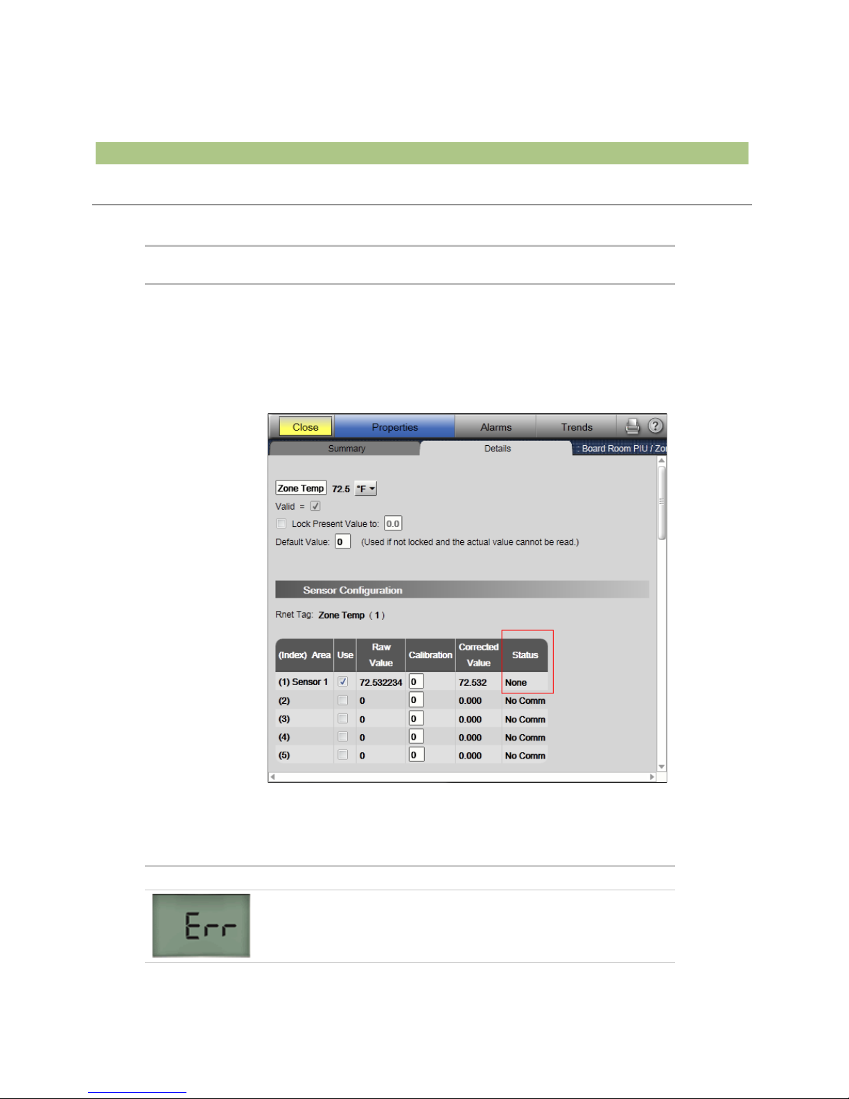
ZS Pro or ZS Pro-F
If display
shows...
Then...
Incorrect or missing
values
Check for errors in WebCTRL® for OEMs.
On the control program's Properties page, select the Rnet Points tab.
Verify that values coming in from the sensors and those going out to the
sensors are expected values.
On the control program's Logic page, double-click the Sensor Binder and
ASVI microblocks to check for problems in the Status and/or Error
columns.
If the Error column shows Resource Allocation, try formatting the
sensor (page 13). If the error is not corrected by formatting, the control
program engineer should reduce the number of items that the sensor is
trying to display.
Nothing
The sensor has no power.
The sensor is not communicating with the network. Check:
• Software/addressing setup
• Wiring connections
• Controller operating status
Troubleshooting
Page 17

13
Aurora UPC ZS Zone Sensors Installation Guide
Characters that
seem out
of place
The sensor may have a memory problem. Try formatting the sensor (page
13).
!
To format a ZS Sensor
Formatting a sensor clears its flash memory. Do either of the following to format a sensor:
• Download the controller that the sensor is connected to.
• Do the following:
a) Remove the wiring connector from the sensor.
b) Note the current position of the DIP switches.
c) Set all DIP switches to the ON position.
d) Reattach the wiring connector to format.
e) After approximately 3 seconds, remove the wiring connector.
f) Set the DIP switches back to their original position.
g) Reattach the wiring connector.
NOTE If you move a sensor from one controller to another controller that has a different control program, format
the sensor.
Page 18

Page 19

Revision Guide:
Pages:
Description:
Date:
By:
All
First Published
15 Apr 2014
DS
Page 20

©2014 The manufacturer has a policy of continual product research and development and reserves the right to change design and specifi cations without notice.
Product: Aurora UPC ZS Zone Sensors
Document Type: Installation Guide
Part Number: IG1582EW
Release Date: 04/14
 Loading...