

Aurora VSN-ENVIRO-ENTRY, VSN-ENVIRO-CMML Installation Manual
THE MANUAL: AURORA ENVIRONMENTAL
Model Number:
VSN-ENVIRO-ENTRY
VSN-ENVIRO-CMML

1
Aurora Environmental Appliance
Installation Guide
Models VSN-ENVIRO-CMML
and VSN-ENVIRO-ENTRY
This installation document covers the details for installing the Aurora Environmental Appliances (AECommercial and AE-Entry) hardware to
Appliance, the Management System (for example, Aurora Vision Prime Edition) collects and analyzes
environmental data for comparison to predicted environmental data and actual inverter/solar panel
output.
The RS485 port of the Aurora Environmental Appliance is attached via low-voltage wires to the
monitoring or management system and communicates information to the management system using
the ModBus protocol. The weather station is powered via 24VDC power, which is typically available
from the data collection hardware of the management system.
Once the hardware is installed, you will need to login to the management system website to verify the
Internet is connected properly and verify that the data in being received.
sense environmental variables
. Through the Environment
The Aurora Environmental is SunSpec compliant and uses a 2-wire half duplex serial port for Modbus
communication to a host. Contact Power-One if you need to modify or program the unit or change the
Modbus address.
P/N VS814-A01, Commercial Model, P/N VS812-A01, Entry Model 4/30/2012 Copyright © 2011, 2012 Power-One, Inc.
Power-One, Aurora Universal, and all associated logos are trademarks of Power-One, Inc. All rights reserved.
2
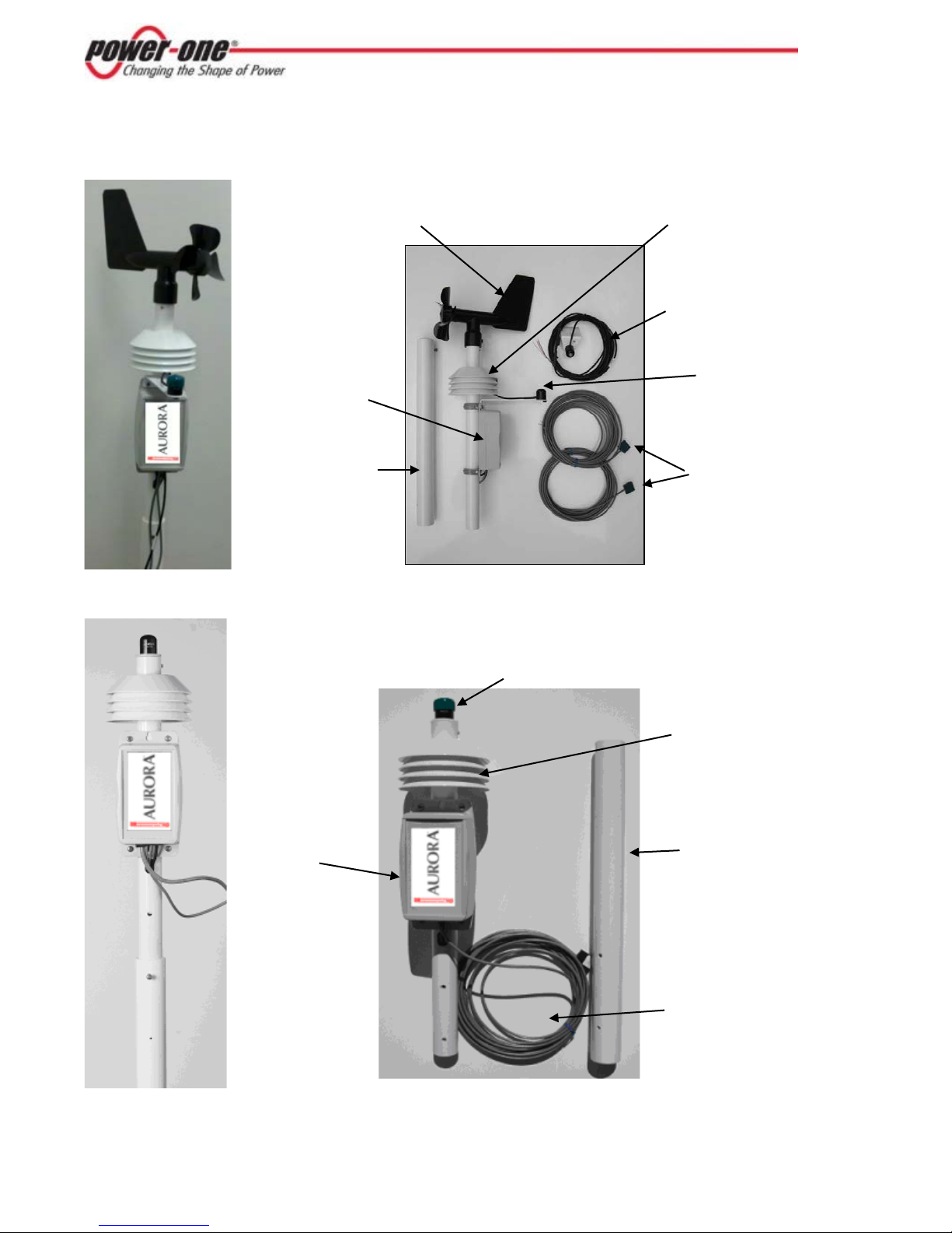
Aurora Environmental Installation Overview
Pyranometer
Ambient
Connector Case
PV Panel
Second Pyranometer
Vane for Wind
Mounting
Pyranometer
Mounting
Connector Case
PV Panel
Ambient
AE-Commercial
AE-Entry
Speed and Direction
Mast
Temperature Sensor
(For Solar Panel Plane)
Temperature Sensors
Temperature Sensor
Mast
Temperature Sensor
3
Installation Steps
We supply:
You supply:
Aurora Environmental Appliance,
Mounting Hardware
1 Select Location for the AE Weather Station
2 Make Connections to 24VDC Power
3 Make Connections to Management System through RS485
4 Install PV Panel Temperature Sensor;
For Commercial Version, Install Secondary Pyranometer and PV Panel Sensor
5 Complete Mounting of the AE Weather Station
6 Verify and validate the Installation via the Management System
Equipment and Supplies
which includes:
Aurora Environmental Weather Station
PV Panel Temperature Sensor
Second Pyranometer (Commercial Model Only)
Second PV Panel Temperature Sensor (Commercial Model Only)
Tripod or pole mount base
Guy wire kit, if necessary
24VDC Power
Twisted Pair Wires
Site Selection and Mounting
Weather Station Location
The ideal site is level and well away from obstructions such as buildings, tress, and steep slopes. The
weather station is typically pole or tripod mounted.
Take into account the needs for all attached sensors to determine the optimal mounting location.
Ambient air temperature and irradiance measurements can be affected by obstructions, local
topography, and surface type. Each site is different and presents unique challenges. By far the most
important consideration is obstruction.
• Objects that are 10 degrees or more above the horizontal plane must not block irradiance.
• Ambient air temperature measurement should be placed away from any dark, heat-absorbing surface
(asphalt, dark-colored surfaces) and should be no closer than 4 times the obstruction’s height.
A simple way to think of obstruction is the rule of 10. If the obstruction is at a distance of at
least 10 times its height above the weather station, you’re good.
Towers can be used to raise the weather station above low-lying obstructions.
Weather Station Mounting Requirements
Mount the support mast securely to a support structure. Mounting equipment is sold as an accessory.
The mast may also be attached to a support structure using U-Bolts. Do not tighten the support
structure to the unit, as directional orientation will be required.
Rotate the assembled unit until the electronics enclosure faces TRUE SOUTH or TRUE NORTH if you
are in the northern or southern hemisphere, respectively. Secure the support mast to the assembly.
4
Lining up the two holes in each mast prevents rotation. At this point the entire unit should be secured
to the support structure.
It is crucial that the device be oriented as precisely as possible. For the Commercial version, the wind
direction measurement is directly related to this positioning.
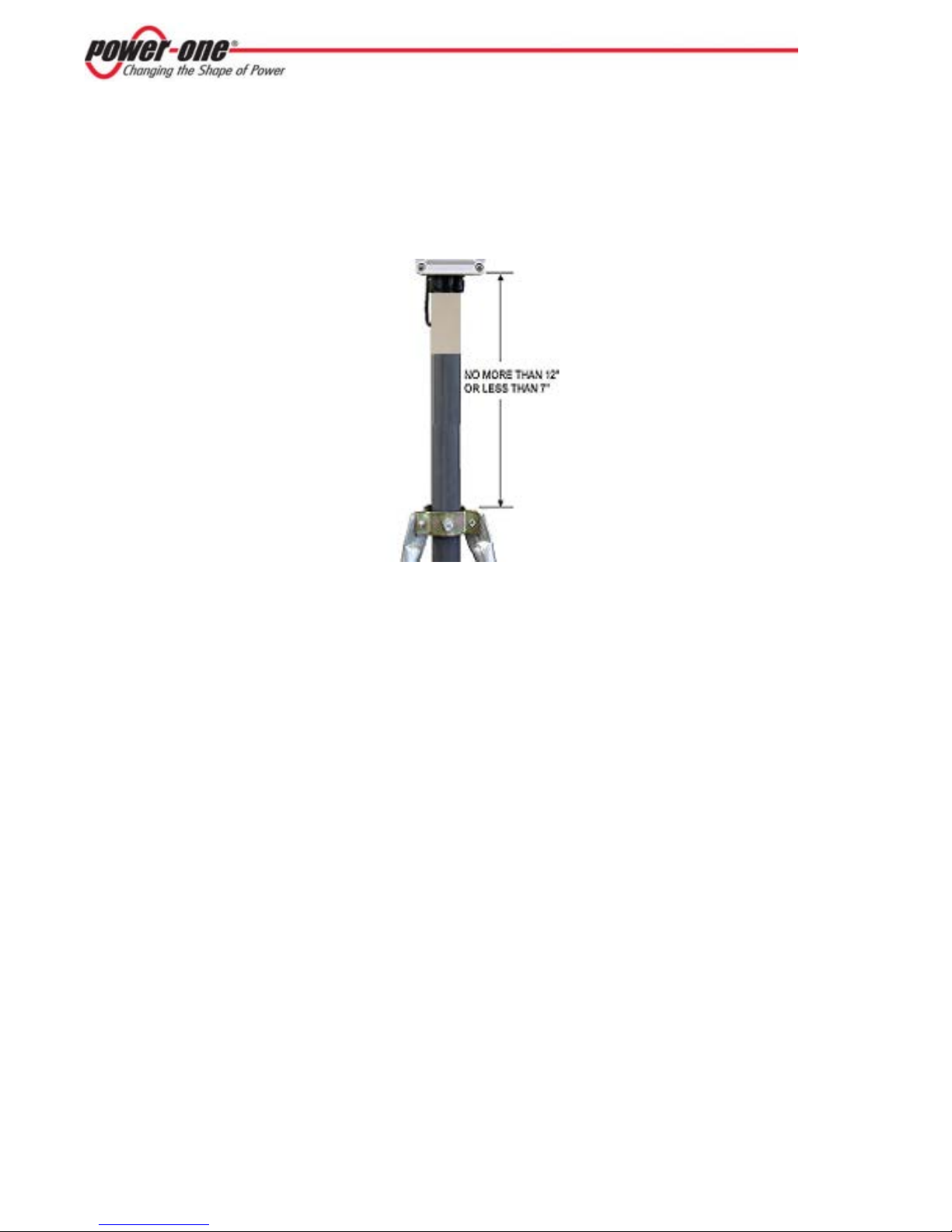
Regardless of how you mount the system, the bottom of the electronic enclosure should not extend
more than 12” or less than 7” above the support of the mounting tube.
Other Mounting Considerations
The exact method of mounting the weather station is left to the installer. However, there are some
guidelines and recommendations to consider.
• The environmental unit is designed to withstand very harsh weather conditions. Refer to the data for
individual sensors for the ranges at which measurements remain accurate.
• The environmental unit weighs approximately 7 lbs. Pole mounts in the ground or attached to
structures that support up to 50 lbs are recommended.
• For ground tripod mounts, the ground should be as level as possible.
• For roof mounts, avoid locating the station near any heat sources such as chimneys or vents. Do not
install on an existing mast unless you know the mast can take the additional weight of the weather
station. When roof-mounting the sensor assembly, the unit should be mounted toward an edge of the
roof preferably on the prevailing wind side of the building and should be at least 2-1/2 feet above the
roofline.
• The weather station unit should be mounted at least 5 feet off the ground. Surrounding terrain and
structures may dictate a much higher mount.
• If the weather station is mounted more than 10 feet off the ground, guy wires should be used to secure
the mount. Guy wire attachments must not interfere with instruments.
• Wall-mounting, pole-mounting, or tripod kits are available. Contact your Power-One distributor.
• Test the system at ground level and make sure it operates properly prior to final mounting.

5
Sensor Mounting Requirements
Global Irradiance
The pyranometer is attached to the sensor assembly and is oriented to measure global irradiance. To
accurately measure this quantity the sensor must be level, orientated either TRUE SOUTH or TRUE
NORTH if you are in the northern or southern hemisphere, respectively, and objects above 10° above
the horizontal plane must not block the sensor.
Be sure to remove the protective green cap from all Pyranometers so they can measure insolation.
Plane-of-Array Irradiance (Commercial Model Only)
The plane-of array pyranometer is mounted on the side of the solar array. The sensor should be at the
same zenith and azimuth angle as solar array to correctly measure the plane-of-array irradiance.
Anemometer (Commercial Model Only)
The anemometer is directly attached to the top of the sensor assembly. For correct wind direction
operation the AE-Commercial must be oriented correctly.
By default the weather station is configured for operation in the Northern hemisphere. This requires
that the irradiance sensor faces due south. If the weather station is going to be used in the Southern
hemisphere it must be mounted with the irradiance sensor facing north. In addition, the hemisphere
jumper inside the AE-Commercial must be changed from Northern to Southern.
 Loading...