


THE MANUAL: TRIO-20.0/27.6-TL
Model Number: TRIO-20.0-TL-OUTD-US
TRIO-27.6-TL-OUTD-US

AURORA® TRIO
Photovoltaic Inverters
TRIO-20.0/27.6-TL US
Technical Manual

Page 2 of
114 Technical Manual: TRIO-20.0/27.6-TL US BCG.00627_AA
Copyright © 2013 Power-One Renewable Energy Solutions LLC. All rights reserved. No part of this
document may be reproduced in any form or by any means without the prior written permission of
Power-One Renewable Energy Solutions LLC. Power-One Renewable Energy Solutions LLC makes
no representations, express or implied, with respect to this document or any of the equipment
and/or software it may describe; including (without limitation) any implied warranties of utility, or
merchantability for any particular purpose. All such warranties are expressly disclaimed. PowerOne Renewable Energy Solutions LLC, its subsidiaries, affiliates, distributors and dealers shall not
be liable for any indirect, special, incidental, or consequential damages under any circumstances.
Power-One Renewable Energy Solutions LLC reserves the right to make changes to this document
without notice and shall not be responsible for any damages, including indirect, special, incidental
or consequential damages, caused by reliance on the content presented, including, but not limited
to, any omissions, typographical errors, arithmetical errors or listing errors. All trademarks, logos,
trade names, service marks and copyrighted materials used in this document are the property of
their respective owners. Failure to designate a mark as registered does not mean that such mark is
not a registered trademark. The Power-One name and logo are registered trademarks of PowerOne, Inc. in the U.S.A. and other countries. All rights reserved. No licenses are conveyed herein,
implicitly or otherwise, under any intellectual property rights.
Power-One
Renewable Energy Solutions LLC
740 Calle Plano
Camarillo, California, 93012
United States
YOUR WKtZͲKEDISTRIBUTOR
SOLIGENT
800-967-6917
www.soligent.net

Page 3 of
114 Technical Manual: TRIO-20.0/27.6-TL US BCG.00627_AA
Contents
PART 1 INTRODUCTION & SAFETY ............................................................................................................................. 4
1.1 INTRODUCTION ......................................................................................................................................................................... 5
1.2 SAFETY ........................................................................................................................................................................................... 7
PART 2 UNPACK AND SELECT INSTALLATION LOCATION .............................................................................. 16
2.1 GENERAL CONDITIONS ........................................................................................................................................................ 17
2.2 SELECT THE INSTALLATION LOCATION ...................................................................................................................... 20
PART 3 MOUNTING AND WIRING ............................................................................................................................. 23
3.1 AVAILABLE VERSIONS .......................................................................................................................................................... 24
3.2 GRAPHICAL REPRESENTATION OF TRIO .................................................................................................................... 26
3.3 WALL MOUNTING ................................................................................................................................................................... 27
3.4 WIRING DETAILS ..................................................................................................................................................................... 29
3.5 SETTING THE COUNTRY STANDARD AND LANGUAGE ......................................................................................... 53
PART 4 OPERATION GUIDE......................................................................................................................................... 54
4.1 GENERAL CONDITIONS ........................................................................................................................................................ 55
4.2 MONITORING AND DATA TRANSMISSION .................................................................................................................. 55
4.3 DISPLAY AND KEYPAD.......................................................................................................................................................... 56
4.4 COMMISSIONING ..................................................................................................................................................................... 61
4.5 DESCRIPTION OF THE MENUS .......................................................................................................................................... 65
PART 5 TROUBLESHOOTING GUIDE ........................................................................................................................ 72
5.1 GENERAL CONDITIONS ........................................................................................................................................................ 73
5.2 ALARM MESSAGES AND DISPLAY CODES .................................................................................................................... 73
5.3 THE POWER 0NE SERVICE CALL...................................................................................................................................... 82
PART 6 MAINTENANCE GUIDE ................................................................................................................................... 83
6.1 GENERAL CONDITIONS ........................................................................................................................................................ 84
6.2 ROUTINE MAINTENANCE ................................................................................................................................................... 85
6.3 OTHER MAINTENANCE ........................................................................................................................................................ 85
6.4 CR2032 BATTERY REPLACEMENT ................................................................................................................................. 86
6.5 STORAGE AND DISMANTLING .......................................................................................................................................... 87
PART 7 APPENDIX .......................................................................................................................................................... 88
7.1 TECHNICAL DATA ................................................................................................................................................................... 89
7.2 FIELD ADJUSTABLE TRIP LIMITS FOR VOLTAGE AND FREQUENCY ........................................................... 103
7.3 MPPT CONFIGURATION EXAMPLES ............................................................................................................................ 104
7.4 ENVIRONMENTAL SENSORS ........................................................................................................................................... 106
7.5 PROTECTIVE DEVICES WITHIN THE AURORA INVERTER ............................................................................... 109
7.6 STRINGS AND ARRAYS ....................................................................................................................................................... 110
7.7 FCC REMARKS ........................................................................................................................................................................ 112
7.8 INDEX OF TABLES AND FIGURES.................................................................................................................................. 113

Page 4 of
114 Technical Manual: TRIO-20.0/27.6-TL US BCG.00627_AA
PART 1 INTRODUCTION & SAFETY

Page 5 of
Part 1 Introduction and Safety
114 Technical Manual: TRIO-20.0/27.6-TL US BCG.00627_AA
1.1 INTRODUCTION
SAVE THESE INSTRUCTIONS. This manual contains important instructions for models indicated
on the front cover that shall be followed during installation and maintenance of the inverter.
1.1.1 PURPOSE
The purpose of this document is to support the qualified technician, who has received training
and/or has demonstrated skills and knowledge in construction, in installing and maintaining this
Power-One AURORA® TRIO Photovoltaic (PV) Inverter. This manual does not cover any details
concerning equipment connected to the inverter such as the solar modules. Information
concerning the connected equipment is available from the respective manufacturer.
1.1.2 INSTALLATION
The installation is to be done by a qualified installer, normally a licensed electrician or contractor,
according to the applicable local code regulations (National Electric Code (NEC), Canadian Electric
Code (CEC), and other).
1.1.3 MAINTENANCE AND SERVICE
Maintenance and service procedures must comply with the manufacturer's documentation. For
more detailed information, see Maintenance, Part 6. Call Power-One Customer Service at 877-2611374 for a list of qualified service contractors.
1.1.4 FIGURES AND IMAGES IN THIS MANUAL
The photos in this manual may differ slightly from the final model shipped and the color of the
components may not match those illustrated; however the information is still applicable.

Page 6 of
One’s AURORA
Part 1 Introduction and Safety
114 Technical Manual: TRIO-20.0/27.6-TL US BCG.00627_AA
1.1.5 STORAGE OF THIS INFORMATION
Keep this document in a safe place near the AURORA TRIO Inverter for easy access during
installation and maintenance. It must be accessible for approved service and maintenance
personnel at any time.
1.1.6 ADDITIONAL INFORMATION
More information on PowerTRIO Inverter can be found at www.power-
one.com.

Page 7 of
Symbol
Usage
Indicates a hazardous situation that can result in deadly electric shock hazards,
other serious physical injury, and/or fire hazards.
Indicates directions which must be fully understood and followed in their entirety
in order to avoid potential safety hazards including equipment damage or personal
injury.
The reader should stop, use caution and fully understand the operations explained
before proceeding.
DANGEROUS VOLTAGE
The product works with high voltages. All work on the AURORA Inverter must
follow the described documentation and must comply with all prevailing codes and
regulations associated with high voltages.
Some surfaces may become hot; do not touch the product while it is in operation.
UL1741 Standard for Safety for Inverters, Converters, Controllers and
Interconnection System Equipment for use with Distributed Energy Resources.
CSA-C22.2 No. 107.1-01 - General Use Power Supplies.
Part 1 Introduction and Safety
114 Technical Manual: TRIO-20.0/27.6-TL US BCG.00627_AA
1.2 SAFETY
IMPORTANT SAFETY INSTRUCTIONS!
SAVE THESE INSTRUCTIONS – KEEP IN A SAFE PLACE!
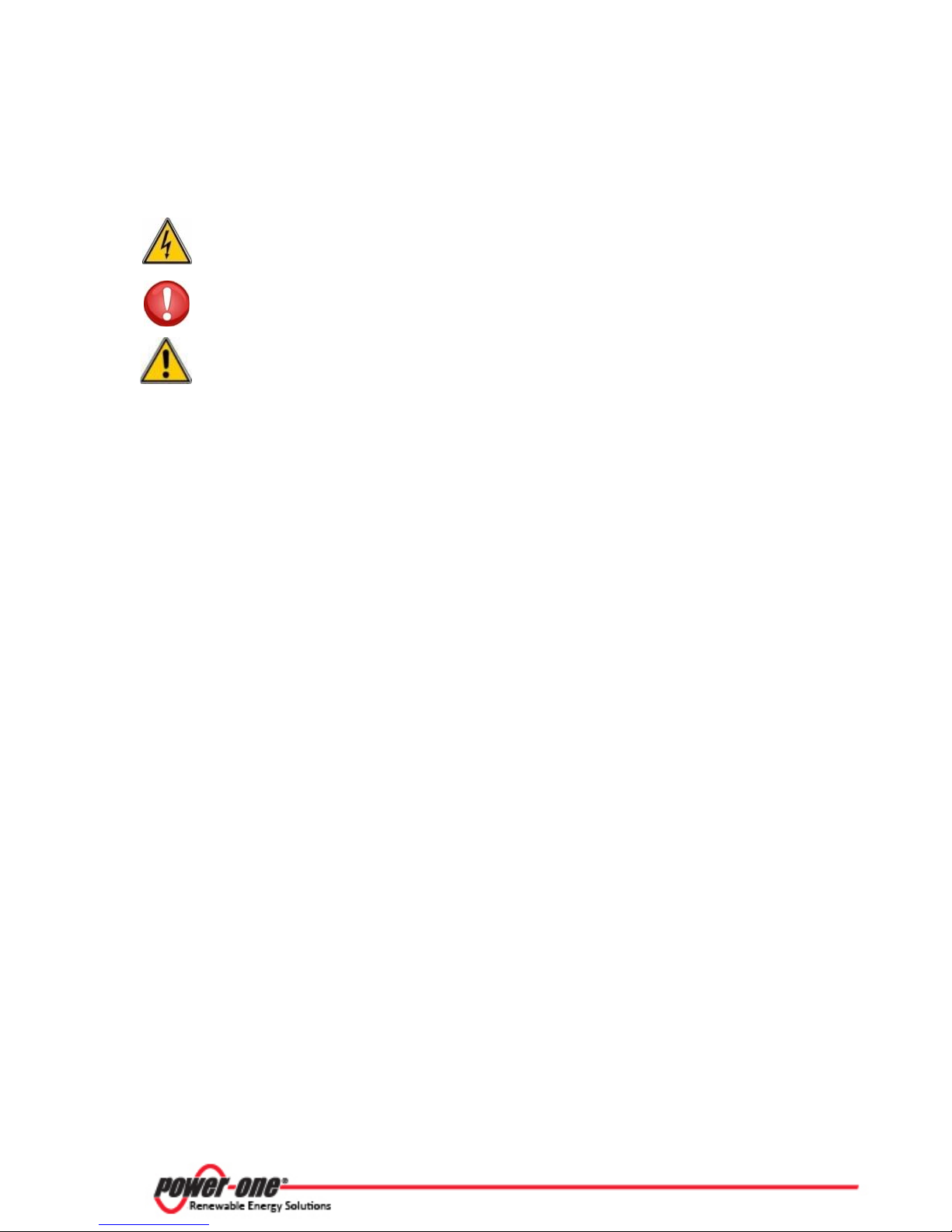
1.2.1 WARNINGS IN THIS DOCUMENT
This is a list of special safety symbols used in this manual that highlight potential safety risks
and/or useful information. The symbol usage is described below:
DANGER:
WARNING:
CAUTION:
WARNING
HOT TEMPERATURE
WARNING
THE INSTALLER MUST READ THIS DOCUMENT IN ITS ENTIRETY BEFORE INSTALLING OR
COMMISSIONING THIS EQUIPMENT.

Page 8 of
System earth conductor (main grounding protective
earth, PE)
Alternating Current (AC) Value
Direct Current (DC) Value
ø
Phase
Grounding (earth)
All operations regarding transport, installation and start up, including
maintenance, must be carried out by qualified, trained personnel and in
compliance with all prevailing local codes and regulations.
Part 1 Introduction and Safety
114 Technical Manual: TRIO-20.0/27.6-TL US BCG.00627_AA
1.2.1.1 Equipment Safety Warnings
In addition to the safety and hazard symbols, the following symbols are also used in this installation
guide:
The equipment has various labels. Those with a yellow background refer to safety concerns. Be sure
to read all labels before beginning installation of the equipment. If any questions arise as to the
meaning or intent of these notices, please contact Power-One Technical Support at 877-261-1374.
1.2.1.2 General Installation Warnings
The AURORA TRIO Transformerless Inverter is designed and tested according to international
safety requirements (UL1741/IEEE1547); however, certain safety precautions must be observed
when installing and operating this inverter. Read and follow all instructions, cautions and warnings
in this installation manual.
WARNING:

Page 9 of
Wiring methods used should be in accordance with the National Electric
Output circuits must be isolated from the enclosure and system grounding,
The Aurora Inverter should be connected only to a dedicated branch circuit.
responsibility of the end user to provide protection for the AC output
with 25 amperes maximum branch circuit overcurrent protection in
accordance with the National Electrical Code, ANSI/NFPA 70.
114 Technical Manual: TRIO-20.0/27.6-TL US BCG.00627_AA
Part 1 Introduction and Safety
1.2.1.3 Assembly Warnings
Prior to installation, inspect the unit to ensure absence of any transport or handling damage, which
could affect insulation integrity or safety clearances; failure to do so could result in safety hazards.
Assemble the inverter per the instructions in this manual. Use care when choosing installation
location and adhere to specified cooling requirements.
Unauthorized removal of necessary protection features, improper use, incorrect installation and
operation may lead to serious safety and shock hazards and/or equipment damage.
1.2.1.4 Electrical Connection Warnings
This grid-tied inverter system operates only when properly connected to the AC utility grid. Before
connecting the services of the AURORA grid-tied inverter to the AC utility grid, contact the local
power distribution company to receive the appropriate approvals. This connection must be made
only by qualified technical personnel.
Code, ANSI/NFPA 70 and/or any prevailing local codes and regulations.
Systems with inverters typically require external disconnect switches or
protective devices (e.g., fusing circuit breakers) depending upon the local
WARNING:
safety regulations.
required by Sections 690-40 and 690-42 of the National Electric Code,
ANSI/NFPA 70, and is the responsibility of the installer.
For models that do not include AC output overcurrent protection, it is the
CAUTION:
circuit.
To reduce the risk of fire, connect Auxiliary Input only to a circuit provided

Page 10 of
WARNING:
114 Technical Manual: TRIO-20.0/27.6-TL US BCG.00627_AA
Part 1 Introduction and Safety
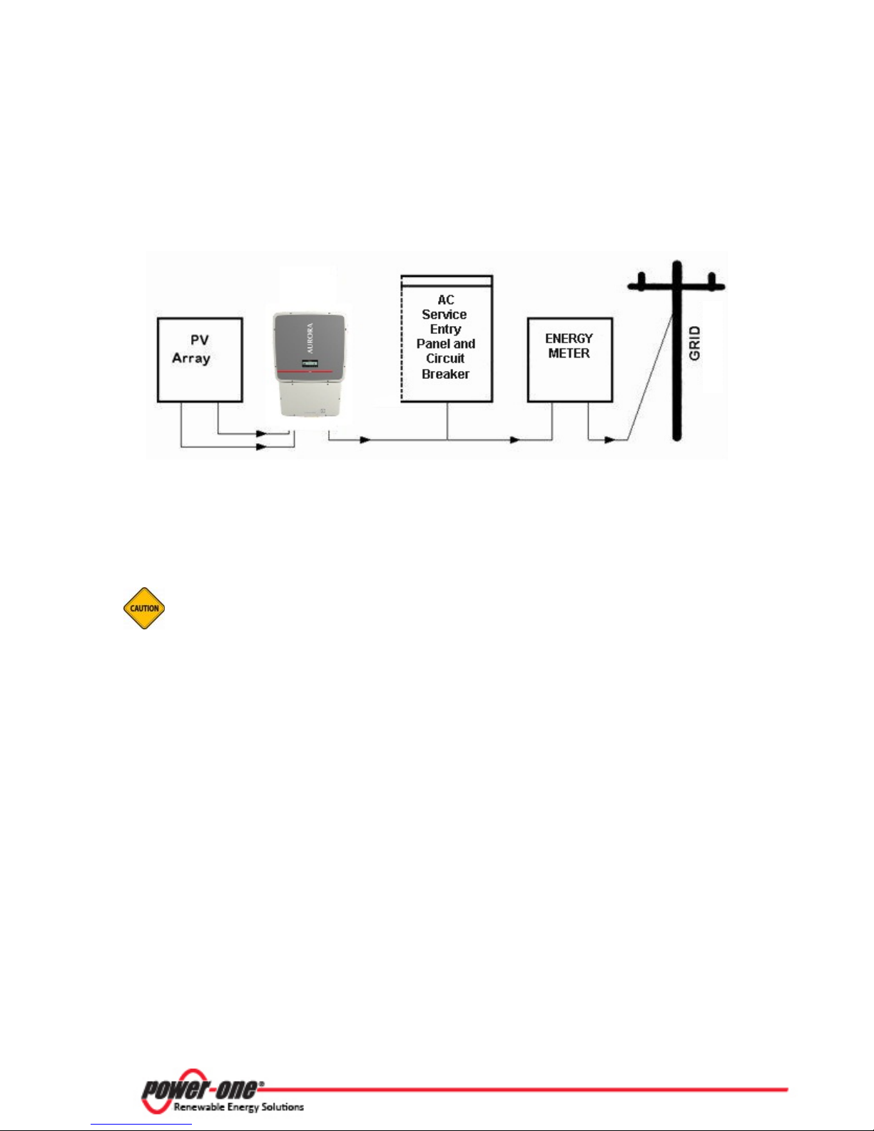
1.2.2 APPROPRIATE USAGE
The AURORA Inverter is a photovoltaic inverter that converts direct current of a PV array into
alternating current and feeds that power into the AC utility grid.
This AURORA Inverter is designed for outdoor use, but can be used indoors if installed to
specified environmental and mounting parameters stated in this manual, and abiding by the
National Electric Code. (See Environmental Conditions in section 1.2.2.2 below and General
Installation Conditions in section 2.2.1 for more information.)
If installed indoors, the inverter must be inaccessible to unqualified
persons.
Figure 1-1: PV array structure in Independent configuration
Page 11 of
accepts no liability for damage of any kind that may arise from incorrect
or careless operation. The equipment must not be used in ways that do not fall
within the intended field of use.
114 Technical Manual: TRIO-20.0/27.6-TL US BCG.00627_AA
Part 1 Introduction and Safety
CAUTION:
Power-One
Figure 1-2: PV array structure in Parallel configuration

Page 12 of
114 Technical Manual: TRIO-20.0/27.6-TL US BCG.00627_AA
Part 1 Introduction and Safety
1.2.2.1 Conditions of Use
The inverter can be used only with photovoltaic modules that do not require
one of the poles to be grounded.
CAUTION:
• The operating current dispersed during the normal operation
in
documented
the technical specifications.
• Only one photovoltaic source can be connected to the input of the inverter (do not connect
batteries or other sources of power supply).
• The inverter can be connected to the utility grid in qualified countries
• The inverter can only be used if all the technical requirements in this manual are observed and
applied.
MUST NOT exceed the limits
only.
1.2.2.2 Environmental Conditions
Adverse or constrained environmental conditions can lead to a reduction in performance. The
equipment can be installed outdoors, but only in environmental conditions that do not prevent
operation. Care must be taken to provide adequate ventilation if installed indoors.
1.2.2.3 Improper or Prohibited Use
The following actions are dangerous and strictly forbidden under the terms of the warranty:
• Installing the equipment in environments with flammable conditions.
• Using the equipment with safety devices not working or disabled.
• Using the equipment or parts of the equipment by connecting it to other machines or
equipment, unless otherwise expressed.
• Modifying areas that are operator restricted and/or altering parts of the equipment in order
to vary the performance or change its protection.
• Cleaning with corrosive products that may corrode parts of the equipment or generate
electrostatic charges.
• Using or installing the equipment or parts of it without having read and correctly
interpreted the contents of this manual.
• Warming or drying rags on unit or accessory parts is dangerous and could compromise the
ventilation and cooling of the components.
Page 13 of
Warning – These servicing instructions are for use by qualified personnel only.
To reduce the risk of electric shock, do not perform any servicing other than that
specified in the operating instructions.
Danger - Be sure all flammable materials including construction items are away
from the unit. Do not install the inverter in or near potentially explosive areas.
Warning – The AURORA TRIO is not provided with an isolation transformer and is
intended to be installed per NFPA 70, 690.35 with an ungrounded PV array.
These models have no grounded input conductors.
114 Technical Manual: TRIO-20.0/27.6-TL US BCG.00627_AA
Part 1 Introduction and Safety
1.2.3 SAFETY INSTRUCTIONS
Do not connect an AURORA Inverter to the AC utility grid until receipt of a letter of authorization
from the authority having jurisdiction.
Install the AURORA Inverter in accordance with the electrical standards prescribed by the
applicable National Electric Code (NEC), Canadian Electric Code (CEC), and/or by other local codes
and regulations.
1.2.3.1 General Information
The equipment has been manufactured in accordance with the strictest accident-prevention
regulations and supplied with safety devices suitable for the protection of components and
operators. Inform Power-One about non-standard installation conditions.
Maintenance operations must be carried out according to the Maintenance section in Part 6 of this
manual.
It is essential to provide operators with correct information. They must read and comply with the
technical information given in the manual and any other attached documentation.
The instructions given in the manual do not replace the safety devices and technical data for
installation and operation mounted on the product. They do not replace the safety regulations
enforced in the country of installation and common sense rules.
Do not use the equipment if any operating anomalies are found. Avoid temporary repairs.

Page 14 of
Warning - Certain parts may be extremely hot immediately following shut down
due to normal elevated surface temperatures (e.g. transformers, capacitors, coils
etc.).
114 Technical Manual: TRIO-20.0/27.6-TL US BCG.00627_AA
Part 1 Introduction and Safety
All repairs should be carried out using only qualified spare parts, which must be installed in
accordance with their intended use and by a licensed contractor or authorized Power-One Service
representative.
Liabilities arising from commercial components are delegated to their respective manufacturers.
1.2.3.2 Thermal Hazard
Prior to touching any part of the inverter use care to ensure surfaces and equipment are at touchsafe temperatures and voltages before proceeding.
The customer and/or installer must appropriately instruct the operators or anyone who may come
near the equipment, and highlight, if necessary with notices or other means, the hazardous areas or
operations: magnetic fields, hazardous voltages, high temperatures, possibility of discharges,
generic hazard, etc.
Anytime the inverter has been disconnected from the AC utility grid, use extreme caution as some
components can retain charge sufficient to create a shock hazard. To minimize occurrence of such
conditions, comply with all corresponding safety symbols and markings present on the unit and in
this manual.
1.2.3.3 Clothing and Protective Devices
• Appropriate Personal Protective Equipment (PPE) must be worn at all times when
operating or servicing this equipment.
• All operations on the equipment should be performed with properly electrically insulated
instruments.

Page 15 of
114 Technical Manual: TRIO-20.0/27.6-TL US BCG.00627_AA
Part 1 Introduction and Safety
1.2.3.4 Location of Safety Notices and Labels
Please note the location of safety notices on the AURORA Inverter for notification and protection.
They are located on both side panels of this unit.
Labels are not to be hidden with external objects or parts such as rags, boxes, or other such
equipment. They should be cleaned periodically and always maintained in view.
1.2.4 CONDITIONS OF WARRANTY
Warranty conditions are described in a certificate supplied with the equipment. The warranty is
understood to be valid if the user observes what is described in this manual. Any conditions
deviating from those described must be explicitly agreed upon in writing.
After inspecting the TRIO Inverter, fill out the warranty information and submit it to Power-One.
Submitting this information will register the unit with the manufacturer and the owner will receive
technical updates.
Warranty exclusions can be found on the Power-One Renewable Energy website in the download
section of the AURORA TRIO product page.

Page 16 of
114 Technical Manual: TRIO-20.0/27.6-TL US BCG.00627_AA
PART 2 UNPACK AND SELECT
INSTALLATION LOCATION

Page 17 of
During transportation the TRIO equipment should only be stacked three high.
it can withstand a maximum load of four pieces of
DO NOT stack with equipment or products other than those indicated.
Part 2 Unpack and Select Installation Location
114 The Manual: TRIO-20.0/27.6-TL US BCG.00627_AA
2.1 GENERAL CONDITIONS
Some specifications are not applicable to small equipment or components.
2.1.1 TRANSPORTATION AND HANDLING
Transportation of the equipment, especially by road, must be carried out by suitable ways and
means for protecting the components (in particular, the electronic components) from violent
shocks, humidity, vibration, etc.
can create dangerous
For storage purposes,
WARNING
equipment (stacked five high), if stored correctly.
swinging.
During handling, do not make any sudden or fast movements that
2.1.2 LIFTING
Power-One packages and protects individual components using suitable means to make their
transport and subsequent handling easier. Due to the weight and complexity of this equipment,
Power-One recommends the process of loading and unloading of this equipment be done by an
experienced or specialized staff knowledgeable in material handling.
Where indicated or where there is a provision, eyebolts or handles can be inserted and used as
lifting points. Do not lift several units or parts of the equipment at the same time, unless otherwise
indicated.
2.1.3 UNPACKING AND CHECKING
Discard packaging elements immediately to avoid injury. When opening the package, check that the
equipment is undamaged and confirm all components are present. If you find any defects or
damage, stop unpacking and consult the carrier, and also promptly inform Power-One.
Page 18 of
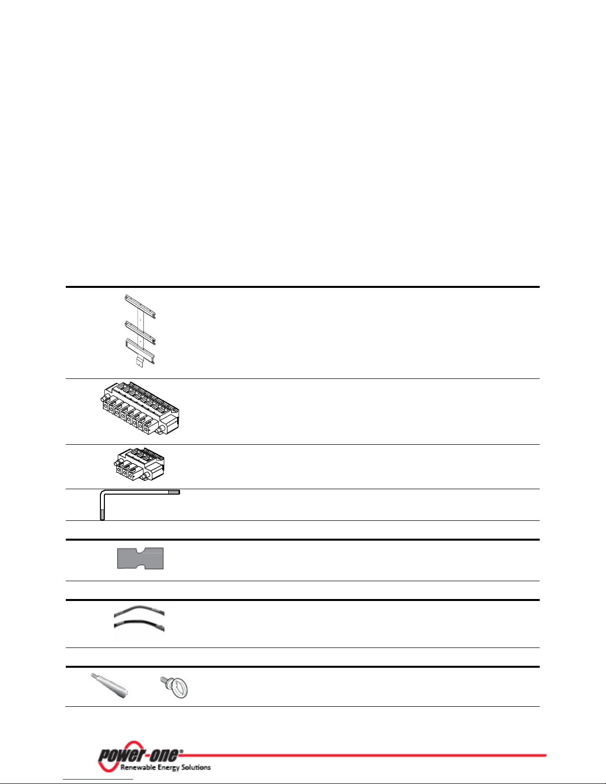
8 pin connector
3 pin connector
2
Torx wrench; 90°; T20; 64x23mm
1
Jumpers for configuration of parallel
input channels
2
Jumper cables for configuration of
parallel input channels
1 Red
1 Black
Optional lifting kit includes handles and
eyebolts for lifting the inverter
1 kit
114 The Manual: TRIO-20.0/27.6-TL US BCG.00627_AA
Part 2 Unpack and Select Installation Location
2.1.4 INCOMING INSPECTION
It is the customer’s responsibility to examine the condition of the unit. Upon receipt of Power-One’s
AURORA grid-tied inverter, please check the following:
• Inspect the shipping container for any external damage.
• Inventory the contents against Table 2-1 below and verify receipt of all items. Use care not
to discard any equipment, parts, or manuals.
• Call the delivering carrier if damage or shortage is detected.
If inspection reveals damage to the inverter, contact the supplier, or authorized distributor for a
repair/return determination and instructions regarding the process.
Table 2-1: Components shipped with equipment
COMPONENTS FOR ALL MODELS
Mounting bracket (1),
wall anchor, screw, washer (10 each)
COMPONENTS FOR -S MODELS ONLY
QTY
1 kit
4
QTY
COMPONENTS FOR –S1, -S1A, -S1B MODELS ONLY QTY
OPTIONAL COMPONENTS AVAILABLE FROM POWER-ONE
QTY

Page 19 of
INVERTER UNIT
Weight:
TRIO-20.0: 132 lbs/60 kg
TRIO-27.6: 143 lbs/65 kg
Number of lifting points : 4
and should be lifted by
kit, with
One and can be used to assist in
hanging the inverter on the
OPTIONAL LIFTING KIT
mounting kit with
handles and eyebolts
COMBINER BOX UNIT
Weight:
-S version: 19 lbs/9 kg
-S1, -S1A, -S1B: 25 lbs/11 kg
114 The Manual: TRIO-20.0/27.6-TL US BCG.00627_AA
Part 2 Unpack and Select Installation Location
2.1.5 HANDLING THE TRIO
The AURORA TRIO Inverter unit and wiring box arrive unattached and are installed separately to
ease installation. When mounting the TRIO, it is recommended to install the wiring box first and
complete all necessary wiring and conduit connections before mounting and attaching the inverter
unit.
The inverter portion weighs 132
pounds or more, depending on the
version,
two persons.
An optional lifting
handles and eyebolts for lifting the
inverter, is available from Power-
mounting bracket.
M 12
The wiring box weight is listed
below:

Page 20 of
The installation must be done by qualified installers and/or licensed
grid (power disconnect switch open) and with the photovoltaic panels shaded
Part 2 Unpack and Select Installation Location
114 The Manual: TRIO-20.0/27.6-TL US BCG.00627_AA
2.2 SELECT THE INSTALLATION LOCATION
2.2.1 GENERAL INSTALLATION CONDITIONS
electricians according to the applicable local code regulations (National Electric
Code, Canadian Electric code, and other).
The installation must be carried out with the equipment disconnected from the
WARNING
or isolated.
2.2.1.1 Environmental Check
• See Technical Data in Appendix, Part 7 to check the environmental parameters to be
observed (degree of protection, temperature, humidity, altitude, etc.).
• Do not install inverter where it could be exposed to direct sunlight to avoid unwanted
power reduction due to an increase in the internal temperature of the inverter.
• Do not install in small closed rooms where air cannot circulate
• Due to acoustical noise (about 50dBA at 1 m) from the inverter, do not install in rooms
where people live or where the prolonged presence of people or animals is expected.
• To avoid overheating, always make sure the flow of air around the inverter is not
blocked.
• Do not install in places where gases or flammable substances may be present.
freely.

Page 21 of
When choosing the place of installation, comply with
the following conditions:
suitable for
where all switch handles and
Install at eye level so the display and status LEDs can
be seen easily.
to allow for normal
(Covers will
NO - direct
NO - heavy snow
NO - air flow
YES
YES
YES
114 The Manual: TRIO-20.0/27.6-TL US BCG.00627_AA
Part 2 Unpack and Select Installation Location
2.2.2 INSTALLATION POSITION
sunlight
Figure 2-1: Outdoor installation examples
restricted
accumulation
Install on a wall or strong structure
bearing the weight.
Install vertically with a maximum incline of +/- 5°.
If the inverter is tilted greater than the maximum
incline, heat dissipation can be inhibited, resulting in
automatic power reduction.
Install in safe place
controls remain easy to reach.
Maintain clearance distances
control and maintenance operations.
need to be removed to carry out maintenance of the
hardware and software of the inverter.)
Figure 2-2: Wall positioning

Page 22 of
For multiple-inverter installations, position the
inverters side-by-side.
Maintain minimum clearances between inverters.
Individual clearances cannot overlap.
arrangement, position the inverters in a staggered
114 The Manual: TRIO-20.0/27.6-TL US BCG.00627_AA
Part 2 Unpack and Select Installation Location
If the space available does not allow the side-by-side
arrangement as shown in the figure below so that
heat dissipation does not affect other inverters.
Figure 2-3: Staggered installation arrangement
For staggered or side-by side arrangements; make sure to add the minimum distances between
inverters where applicable, as illustrated in Figure 2-4.
Figure 2-4: Installation of multiple inverters with additive clearances

Page 23 of
114 Technical Manual: TRIO-20.0/27.6-TL US BCG.00627_AA
PART 3 MOUNTING AND WIRING

Page 24 of
TRIO-20.0-TL-OUTD-S-US-480
TRIO-20.0-TL-OUTD-S1B-US-480
(HxWxD):
41.7 x 27.6 x 11.5 in
1061 x 702 x 292 mm
: 157 lbs./71kg
TRIO-27.6-TL-OUTD-S-US-480
(HxWxD):
41.7 x 27.6 x 11.5 in
1061 x 702 x 292 mm
: 168 lbs/76kg
DC Disconnect Switch
DC Disconnect Switch
DC Fuses
Class II DC Surge Protection
DC Disconnect Switch
DC Fuses
Class II DC Surge Protection
Class II AC Surge Protection
DC Disconnect Switch
DC Fuses
Class II DC Surge Protection
AC Fused Disconnect Switch
114 The Manual: TRIO-20.0/27.6-TL US BCG.00627_AA
Part 3 Mounting And Wiring
3.1 AVAILABLE VERSIONS
The inverters can be divided into two groups according to their rated output power of 20.0 kW or
27.6 kW. For inverters of equal output power, the differences between models are the
configuration of the wiring box. A description of the four wiring box versions can be found in Table
3-1 below.
20.0 kW MODELS
TRIO-20.0-TL-OUTD-S1-US-480
TRIO-20.0-TL-OUTD-S1A-US-480
27.6 kW MODELS
TRIO-27.6-TL-OUTD-S1-US-480
TRIO-27.6-TL-OUTD-S1A-US-480
TRIO-27.6-TL-OUTD-S1B-US-480
Table 3-1: Wiring box configurations available
TRIO-20/27.6-TL-OUTD-S-US-480
TRIO-20/27.6-TL-OUTD-S1-US-480
Dimensions
Weight
Dimensions
Weight
TRIO-20/27.6-TL-OUTD-S1A-US-480
TRIO-20/27.6-TL-OUTD-S1B-US-480

Page 25 of
2
3 4 5
1
Made in Italy
114 The Manual: TRIO-20.0/27.6-TL US BCG.00627_AA
Part 3 Mounting And Wiring
3.1.1 NAMEPLATE
The nameplate shown below is affixed to the inverter and provides the following information:
1. Product origin
2. Model name
3. DC input data
4. AC output data
5. Certification
Figure 3-1: Sample nameplate for TRIO-20.0-TL-OUTD-S1-US-480
Technical data in this manual does not, however, supersede the data on the labels affixed to the
equipment.

Page 26 of
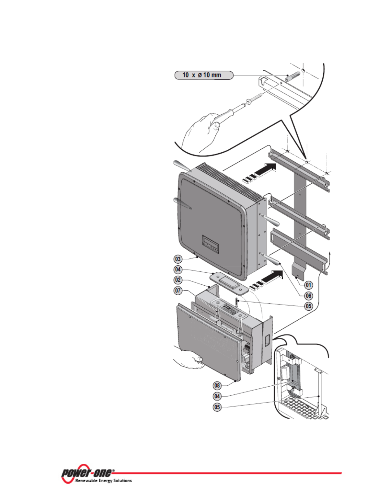
Ref.
Description
01
Mounting bracket
02
Wiring box
03
Inverter
04
Coupling
connector cover
05
Clamp screw
06
Handles (optional,
see Wall Mounting
section below for
information)
07
Connector screws
08
Wiring box front
cover
114 The Manual: TRIO-20.0/27.6-TL US BCG.00627_AA
Part 3 Mounting And Wiring
3.2 GRAPHICAL REPRESENTATION OF TRIO
Figure 3-2: Graphical representation of TRIO parts with references
Page 27 of
3.3 WALL MOUNTING
Included in the shipping package is a
mounting kit with screws and wall
Drill the holes required using a drill
of the rear
position (see
the connector between the
screws will then be used to attach the
the cover in the special pocket
provided at the rear of the wiring box
04.
114 The Manual: TRIO-20.0/27.6-TL US BCG.00627_AA
Part 3 Mounting And Wiring
plugs provided for mounting the metal
bracket to a concrete wall.
Position the wall bracket 01 perfectly
level on the
template.
wall and use it as a drilling
with 10mm bit.
Attach the bracket to the wall with the
ten wall anchors, 10mm in diameter,
(supplied in mounting kit).
Hook the wiring box 02 on the bracket
by inserting the heads
screws in the slots in the bracket.
It is not necessary to install the inverter
unit 03 at this stage. Power-One
recommends making the wiring box
connections before attaching and
mounting the inverter unit.
Ensure that the DC disconnect switch
handle is in the OFF
3.4.2.1).
Remove the front cover of the wiring
box 08 and follow the wiring details in
section 3.4 below to complete the
necessary connections.
Upon completion of the wiring, loosen
the connector screws 07 to remove the
coupling connector cover 04 that
protects
wiring box and the inverter unit. (These
wiring box to the inverter unit.)
Store

Page 28 of
Attach and mount the inverter unit. (Do not
replace the wiring box front cover until the
the bracket by
connect the two parts by tightening the clamp
screw
using 20mm size socket.
Once the wiring box and inverter unit are
connected, tighten the two connector screws
with at least 18 in-lbs (2Nm) torque to ensure
proper waterproof sealing.
05
07
05
05
114 The Manual: TRIO-20.0/27.6-TL US BCG.00627_AA
Part 3 Mounting And Wiring
Figure 3-3: Wall mounting example
inverter unit is attached.)
Hook the inverter unit 03 to
inserting the head of the rear screws in the slots
as shown in the figure.
To make lifting easier, an optional lifting kit is
available from Power-One containing handles
and eyebolts that can be attached to holes in the
side of the inverter unit.
Working from the bottom of the wiring box,
05
The clamp screw 05 is accessed from the bottom
of the wiring box and used to secure the wiring
box to the inverter unit.
with at least 13.3 ft-lbs (18Nm) torque using a
13mm size socket. The screws are located
inside the top of the wiring box.
Replace the front cover of the wiring box 08
07

Page 29 of
It is the responsibility of the installer to provide external disconnect switches
not provided with an isolation transformer and is
TRIO-20.0-TL US
TRIO-27.6-TL US
Type
Automatic circuit breaker with differential thermal magnetic
protection
Voltage/Current
rating
40A/600V
50A/600V
WARNING
Part 3 Mounting And Wiring
114 The Manual: TRIO-20.0/27.6-TL US BCG.00627_AA
3.4 WIRING DETAILS
3.4.1 PREPARING TO CONNECT THE GRID-TIED PV INVERTER
and Overcurrent Protection Devices (OCPD) as required by National Electric
Codes and other prevailing regulations.
An automatic overcurrent device (e.g., circuit breaker) must be installed
between the TRIO Inverter and the AC utility grid.
The AURORA TRIO is
intended to be installed per NFPA 70, 690.35 with an ungrounded PV array.
3.4.1.1 External AC disconnect switch
To protect the AC connection line of the inverter, Power-One recommends the following
characteristics when installing a device for protection against overcurrent:
3.4.1.2 Checking the correct polarity of the strings
Verify that the DC voltage in the wiring box has the correct polarity and is
within the operational range
Using a voltmeter, check that the voltage of each string has the correct polarity and at the coldest
expected operating temperature, will fall within the input voltage limits accepted by the inverter
(see Technical Data in Appendix, Part 7).
.
 Loading...