

Aurora PVI-DESKTOP, PVI-DESKTOP-BT-AU, PVI-DESKTOP-BT-US, PVI-DESKTOP-AU, PVI-DESKTOP-US Installation And Operator's Manual
...
Rev. 1.3 - Aurora® is a trademark by Power-One - Product is subject to technical improvements
www.power-one.com
Aurora® Power Service USA 877-261-1374
Aurora® Power Service France 00 800 00 28 76 72
Aurora® Power Service Germany 0800-2200211
Aurora® Power Service Italy 00 800 00 28 76 72
Aurora® Power Service Spain 00 800 00 28 76 72
Aurora® Power Service Middle East 00 800 00 28 76 72
Aurora® Power Service Australia +61 2 9735 3111
Aurora® Power Service China +86 755 2988 5888
Aurora® Power Service Singapore +65 6896 3363
Aurora® Power Service Malaysia +603-8025 9963
Model: PVI-DESKTOP-yy-xx
INSTALLATION AND OPERATOR’S MANUAL
MANUALE DI INSTALLAZIONE E OPERATORE
PVI-DESKTOP
Remote controller and monitoring system
INSTALLATION AND OPERATION MANUAL
Note: this document contains information which is the sole property of Power-One
Inc.. No part of it may be copied or circulated without the prior written consent of
Power-One.
KEEP THESE INSTRUCTIONS!
Model number: PVI-DESKTOP-yy-xx Rev. 1.3

Page 2 of 51
REVISION TABLE
Document
revision
Date
Descri
ption of changes
1.0 21/07/2009
First release
1.1 29/12/2009
First revi
sion
1.2 09/12/
2009
Second
revi
sion
1.3 25/07
/2011
Third
revi
sion

Page 3 of 51
CONTENTS
1
MANUAL INFORMATION .............................................................. 5
1.1
SYMBOLS USED........................................................................................ 5
1.2
PURPOSE ................................................................................................. 5
2
PRODUCT INFORMATION ............................................................. 5
2.1
DESCRIPTION OF THE PVI-DESKTOP SYSTEM ............................................. 5
2.2
POSSIBLE USE .......................................................................................... 7
2.2.1 Possible connection to inverters:........................................................... 7
2.2.2 Operative systems compatible for PC connection: ................................. 7
2.3
PACKAGING CONTENTS ........................................................................... 8
2.4
PRODUCT IDENTIFICATION ...................................................................... 9
2.4.1 outer label data ................................................................................... 9
2.4.2 firmware version .................................................................................. 9
2.5
PVI-DESKTOP CONNECTIONS AND INTERFACES ...................................... 10
2.5.1 power supply connector ..................................................................... 12
2.5.2 usb connector .................................................................................... 12
2.5.3 rs485 connector ................................................................................. 12
2.5.4 sd card / sd card slot .......................................................................... 13
2.5.5 reset button ....................................................................................... 13
2.5.6 status led ........................................................................................... 13
2.5.7 bluetooth (optional) ........................................................................... 13
2.5.8 touchscreen ....................................................................................... 14
3
SAFETY WARNINGS .................................................................... 14
4
PVI-DESKTOP INSTALLATION ...................................................... 15
4.1
PRELIMINARY OPERATIONS ................................................................... 15
4.1.1 inverter configuration (radio connection) ............................................ 15
4.1.2 inverter configuration (rs485 wired connection) .................................. 15
4.1.3 tips on the selection of installation location ........................................ 15
4.1.4 positioning of the antenna with respect to the device ......................... 16
4.1.5 radio communication test ................................................................... 16
4.2
SYSTEM INSTALLATION .......................................................................... 17
4.2.1 wall mounting .................................................................................... 17
4.2.2 desk installation ................................................................................. 18
4.3
HOW TO USE – POWER-SUPPLIES ........................................................... 18

Page 4 of 51
5
PVI-DESKTOP SYSTEM OPERATION ............................................ 19
5.1
INITIAL START UP OPERATION ................................................................ 19
5.2
BATTERY DURATION .............................................................................. 19
5.3
START UP............................................................................................... 20
5.3.1 inverter disassociation ........................................................................ 22
5.3.2 association (or configuration) of additional inverters .......................... 23
5.4
BASIC DEVICE SETTING ........................................................................... 23
5.4.1 brightness .......................................................................................... 23
5.4.2 language ............................................................................................ 23
5.4.3 energy saving modality (stand by or “sleep mode”)............................. 23
5.4.4 calibration.......................................................................................... 24
5.4.5 date and time setting ......................................................................... 24
5.5
SD CARD ................................................................................................ 24
5.6
SYSTEM MODE ...................................................................................... 25
5.7
MAIN MENU .......................................................................................... 26
5.7.1 default screen .................................................................................... 26
5.7.2 settings menu .................................................................................... 27
5.7.3 info menu........................................................................................... 27
6
PC CONNECTION ......................................................................... 28
6.1
USB DRIVERS CONFIGURATION .............................................................. 28
6.2
DOWNLOAD GRAPHS FOR ENERGY PRODUCTION ................................... 34
6.3
FIRMWARE UPGRADE ............................................................................ 37
6.3.1 usb firmware updating ....................................................................... 37
6.3.2 firmware upgrade via sd card ............................................................. 41
7
TROUBLESHOOTING ................................................................... 42
8
MAINTENANCE AND CLEANING ................................................. 43
8.1
BATTERIES CHARGE AND DISCHARGE ..................................................... 43
8.2
CLEANING PROCEDURE .......................................................................... 43
9
DISPOSAL.................................................................................... 43
10 AURORA PVI-DESKTOP TECHNICAL DATA .................................. 44
11 CERTIFICATES ............................................................................. 46

Page 5 of 51
1 MANUAL INFORMATION
1.1 SYMBOLS USED
In order to reduce potential safety risks or highlight useful information the following symbols have been
used:
WARNING: Paragraphs marked by this symbol contain actions and instructions which must be
understood and followed carefully to avoid potential damage to the device or injury to persons
NOTE: Paragraphs marked by this symbol contain actions and instructions which must be
understood and followed carefully to avoid damage on installation and malfunction of the
equipment.
1.2 PURPOSE
This manual edited for the installer and user contains important instructions relating to installation, safety
and operation, which must be understood and carefully followed.
2 PRODUCT INFORMATION
2.1 DESCRIPTION OF THE PVI-DESKTOP SYSTEM
The PVI-DESKTOP allows to monitor and display the performance of the AURORA Power-One inverter and
is ideal for residential or small commercial system installations.
The main advantage of using a PVI-DESKTOP lies in the possibility of setting up wireless communication in
the absence of wired communication, thanks to the PVI-RADIOMODULE installation (on every inverter) .
Moreover the large TFT touch screen display allows the data acquired by the system to be easily and
intuitively displayed and processed. In this way the use of an external PC is not strictly
necessary.Connection to an external PC is only necessary for updating the internal firmware or
downloading the data collected and displaying them by using Aurora Communicator.
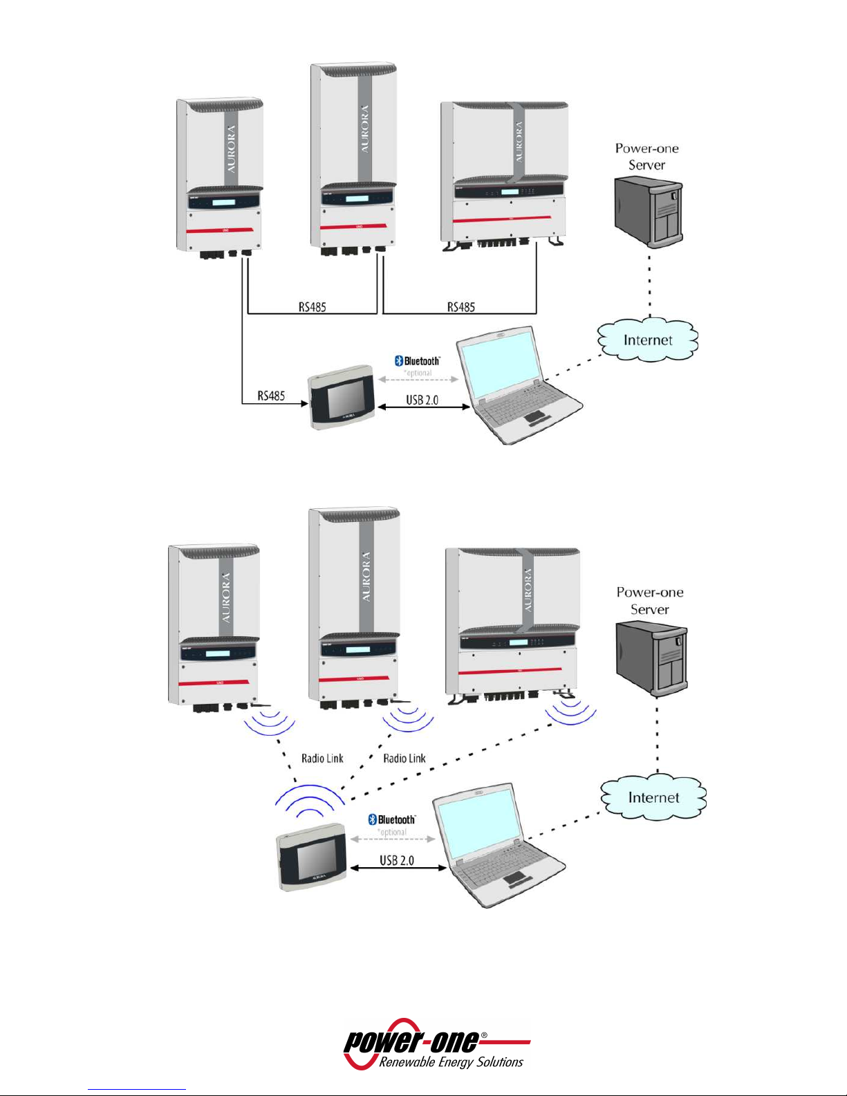
Figure 1 - 2 shows a diagram summarizing the connections possible with the PVI-DESKTOP, both to the
inverters and a traditional PC/Laptop. The interface of the PVI-DESKTOP with the PC/Laptop requires the
installation of the SW Aurora Communicator, available from the CD inside the packaging.
NOTE: it is advisable to periodically check the availability of new SW updates, from the web site
www.power-one.com.
NOTE: the connection of the Power-One server must be only considered as a FW update of the
system using the SW Aurora Communicator installed on the PC/Laptop and connected to the
internet.
Page 6 of 51
Figure 1 – Communication diagram for the PVI-DESKTOP (inverter communication via RS485).
Figure 2 – Communication diagram for the PVI-DESKTOP system (inverter communication via radio
connection).
Page 7 of 51
The wireless and wired (RS485) connections are mutually exclusive, therefore the PVI-DESKTOP
cannot be used in both configurations and the communication channel must always be chosen.
When the use wireless communication is chosen, it is absolutely necessary that every field
inverter has the PVI-Radiomodule installed; it is not possible to use one PVI-Radiomodule and
connect the other inverters to each other via RS485.
2.2 POSSIBLE USE
2.2.1 POSSIBLE CONNECTION TO INVERTERS
• RS485 (cable length up to approx. 1000m, a maximum of 6 inverters)
• Radio (approx. up to 300m in the open/obstacle free, maximum of 6 inverters)
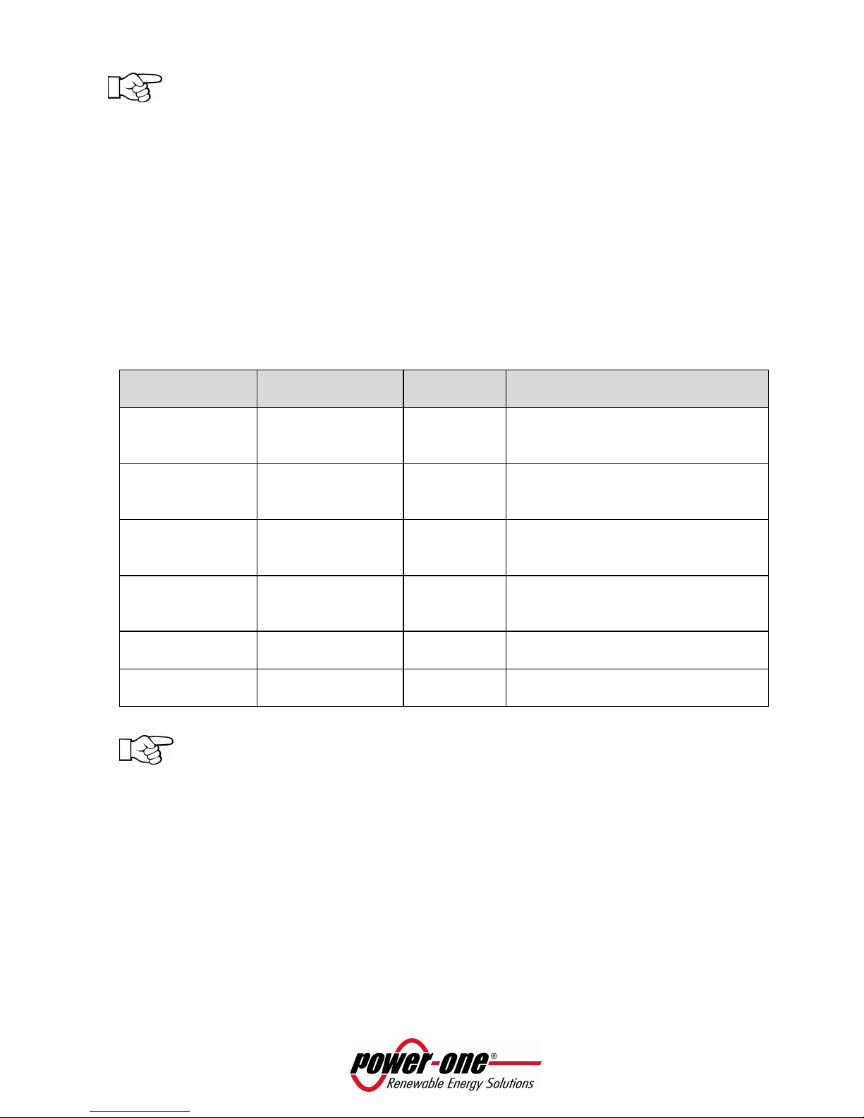
The list of inverters having limitations in using the PVI-DESKTOP , is summarized in the following table:
INVERTER
model
PVI-Radiomodule
compatibility
RS485
compatibility
Notes
PVI-6000 Yes (see note) YES Inverters manufactured before the
week 32/09 require a firmware
upgrade.
PVI-5000 YES YES Inverters manufactured before the
week 32/09 require a firmware
upgrade.
PVI-3600 Indoor YES (see note) YES From the FW 11 version of the PVI-
RADIOMODULE (units manufactured
after the week 25/10).
PVI-2000 Indoor YES (see note) YES From the FW 11 version of the PVI-
RADIOMODULE (units manufactured
after the week 25/10).
PVI-3600 Outdoor
NO YES N/A
PVI-2000 Outdoor
NO YES N/A
All other inverter models (PVI-3.0/3.6/4.2/10.0/12.5-OUTD) in all different versions, there are
no compatibility issues.
2.2.2 OPERATIVE SYSTEMS COMPATIBLE FOR PC CONNECTION
• Windows XP 2002 version(Home and Professional), Service Pack 3
• Windows 2000
• Windows Vista 32bit
• Windows Vista 64bit
• Windows 7 32bit
• Windows 7 64bit

Page 8 of 51
2.3 PACKAGING CONTENTS
The packaging contains, a PVI-DESKTOP and its docking station, and all other accessories shown in the
figure below:
Figure 3 – Packaging Contents
1. PVI-DESKTOP
2. Software and documentation
3. Stylus Pen (already assembled)
4. DC power-supply
5. USB cable
6. SD Card (already assembled)
7. Wall mounting kit (2 dowels + 2 universal screws)
NOTE: The distributor delivered your PVI-DESKTOP to the courier safely packed, and in perfect
condition. By accepting the package, the courier takes responsibility for it up to the delivery.
Despite careful handling by the courier, both the package and its contents may be damaged
during transport.
Product inspection at time of delivery
• Carefully check the device
• Immediately complain to the courier if one of the following is found:
o Damage to the package which could result into device malfunction
o Clear damages to the device

Page 9 of 51
2.4 PRODUCT IDENTIFICATION
Several versions of the PVI-DESKTOP are available, and they differ by their features or added components.
The various models are identified by the P/N ID.
PVI-DESKTOP-yy-xx
US - North America
AU - Australia
No suffix – European version
BT - Bluetooth version
No suffix - Standard version
2.4.1 OUTER LABEL DATA
Figure 4 – Product label
(USA version)
Figure 5 – Product label
(Europe / Australia versions)
2.4.2 FIRMWARE VERSION
The firmware version of the PVI-DESKTOP and of the PVI-RADIOMODULE (if the installed inverter results
already configured to the device) can be consulted following the following procedure:
• Select “Menu” from the main screen
• Once in “Menu” select “Info”
• In “Info” select “ID system” to find out the firmware version installed in each PVI-RADIOMODULE
configurated to each inverter of the system or select “Firmware” to check the version installed in the
PVI-DESKTOP.
Page 10 of 51
2.5 PVI-DESKTOP CONNECTIONS AND INTERFACES
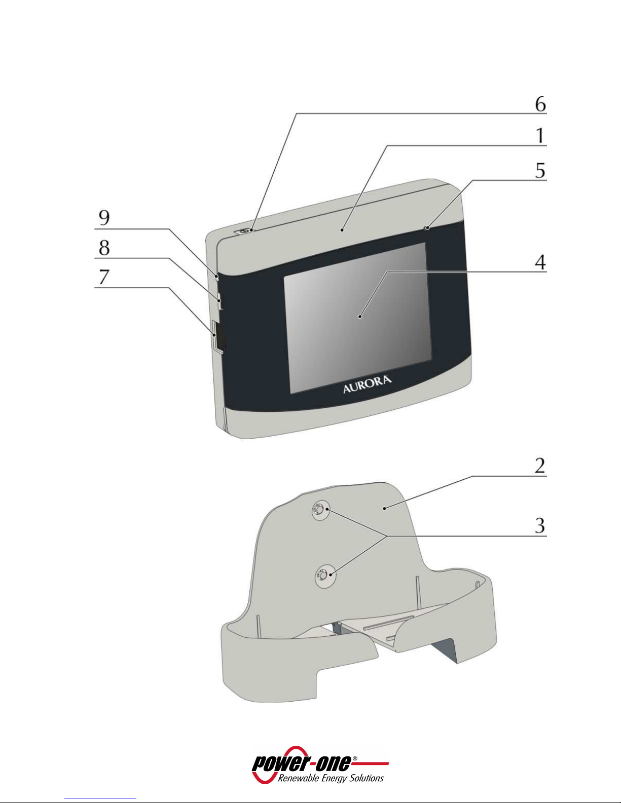
For a correct use of the PVI-DESKTOP it is recommended to carefully observe Figure 6 to be able to identify
each component of the device.

Page 11 of 51
Figure 6 - Components position
1. PVI-DESKTOP
2. Docking station
3. Holes for wall mounting
4. Touch screen display
5. Multicolour LED status indicator
6. Switch ON/OFF button
7. RS485 communication port
8. USB 2.0 communication port
9. Reset button (inner)
10. Power-supply input
11. Sound output holes
12. Stylus Pen groove
13. SD card connector
WARNING: Component 7. is a connector to be used solely and exclusively for connection by
RS485 to the Aurora inverters. On no account use it for anything else (i.e. connection of
Ethernet cables for PC or phone connections) to prevent damage to the communication port.
WARNING: the PVI-DESKTOP is fitted with security labels which, if removed or showing scratch
marks, make the warranty null and void. Maintenance operations and components
replacement on the PVI-DESKTOP can only be carried out by qualified specialist staff.

Page 12 of 51
2.5.1 POWER SUPPLY CONNECTOR
Component 10 in Figure 6 shows the input connector for the power-supply on the back of the device.
Figure 7 shows power-supply polarity.
Figure 7 – Power-supply polarity
WARNING: use the provided power-supply to power the device.
2.5.2 USB CONNECTOR
Component 8 in Figure 6 shows the USB 2.0 interface connector.
The connector is a USB mini B and is used with the cable supplied.
The interface is designed to connect the device to a standard PC with a USB 2.0 port.
Insertion of other types of peripheral such as mass storage keys, external hard disks, mobile
telephones, MP3 players and other devices is not permitted.
Communication with the PC occurs after installation of the special drivers and through the software on the
CD attached to the packaging.
The USB connector can also be used to recharge the PVI-DESKTOP (please refer to paragraph 5.1).
2.5.3 RS485 CONNECTOR
Component 7 in Figure 6 shows the connector entry of the RS485 port. This port is to be used exclusively
for Aurora inverters connection. The connecting cables must have a RJ45 connector with 8 pins and must
be used in accordance to the following table.
Pin N° Function
1 not used
2 not used
3 +T/R
4 not used
5 -T/R
6 not used
7 GND
8 not used
This connection is as an alternative to the radio communication with the inverters.
Page 13 of 51
2.5.4 SD CARD / SD CARD SLOT
The slot dedicated to the SD card is located at the bottom of the PVI-DESKTOP (component 133 in Figure
6).
To remove the SD card, simply press on it until there is a click (Figure 8) and at that point the card will be
automatically pushed out.
The SD card contains some files essential to the system's operation (Language, Sound, Theme) together
with files created during system operation (System – containing all installation data acquired during
operation, SNxxxxxx – containing detailed data of the inverter together with SNxxxxxx acquired during
operation). The SD card can be used to update the system FW, through a procedure described in paragraph
6.3.2.
The memory card can only be reinserted into its slot in one correct way; do not force insertion
as this may break the connector.
NOTE: the SD card can remain indefinitely in its slot. Do not use the SD card as a storage disc for
data unrelated to the operation of the PVI-DESKTOP.
2.5.5 RESET BUTTON
Just above the USB connector, shown in Figure 6, component 9, there is a small hole which allows, through
the use of the stylus pen or other pointed object, the processor to be reset and hence the device restarted.
NOTE: the reset procedure is a recovery process to be used solely and exclusively when the
need arises (i.e. blocking of operation stopage due to exceptional events). The reset procedure
does not damage the device or alter any of its functional characteristics.
2.5.6 STATUS LED
At the top right of the display there is a multicolour LED status indicator for the PVI-DESKTOP system. This
LED will take on different colours depending on the operating status. Figure 6 identifies the position of the
multicolour LED.
The following table describes the different states of operation corresponding to colours that the
multicolour LED can take on.
Flashing red light Flat Battery
Steady yellow Battery charging
Steady green Charged battery and power-supply on
LED off No power-supply connected
Flashing blue Unit in backlight off mode (not yet on standy by)
2.5.7 BLUETOOTH (OPTIONAL)
There is the possibility of having a Bluetooth® module as an optional interface for the PVI-DESKTOP. This
interface allows communication with PCs equipped with Bluetooth® and dedicated software (Aurora
Communicator) which allows data download. Under normal operating conditions, the Bluetooth® function
is disabled to eliminate unnecessary power consumption. To enable this function, access to the
appropriate menu is needed.
For references on the Part Number for the model with integrated Bluetooth® please see paragraph 2.4.
NOTE: we recommend using Bluetooth® only when necessary and disabling it immediately after
use to avoid draining the battery too quickly, when the device is not connected to the network.

Page 14 of 51
2.5.8 TOUCHSCREEN
The PVI-DESKTOP is equipped with a (resistive) touch screen that allows easy and fast navigation through
the menus. At the back (see Figure 6) there is a groove where to insert a stylus pen, for use apply pressure
on the screen. The screen is sensitive to pressure from any object (fingers, pens, etc.) and only a light touch
is needed to activate it.
WARNING: take care to avoid touching the touch screen with sharp or pointed objects or
applying excessive pressure on the surface. Do not scratch, strike violently or scrape the display
surface and only use products specially designed for cleaning LCD screens. Damage to the touch
screen seriously undermines the object's operating efficiency.
NOTE: we recommend using the stylus pen to prevent any staining or soiling to the display
surface.
3 SAFETY WARNINGS
Please pay attention to all safety warnings contained in this manual; failing to comply can cause damage to
the device and danger to people.
The PVI-DESKTOP system can only be opened by specialized Power-One personnel.
The energy production data, saved by the PVI-DESKTOP system can vary from those indicated by the
counter installed in the system. Data acquired from the PVI-DESKTOP directly derive from the inverters and
have no tax value.
For any questions concerning information not reported in this manual, please contact Power-One
assistance service.

Page 15 of 51
4 PVI-DESKTOP INSTALLATION
4.1 PRELIMINARY OPERATIONS
WARNING: the PVI-DESKTOP requires some preliminary steps at the initial start up of the
system. Instructions reported in the next paragraphs must be carefully followed for a correct
start up.
The PVI-DESKTOP can simply be placed on a flat surface or a desk, or can be wall-mounted. This is possible
thanks to the docking station with supporting feet and pre-scoring for the fixing holes.
4.1.1 INVERTER CONFIGURATION (RADIO CONNECTION)
• Check that the PVI-RADIOMODULE card has been correctly installed (see the PVI-RADIOMODULE
manual) if you want to initialize radio communication, and that LED 3 (orange) is flashing (see Figure
10 for LED positioning).
• Check that the Aurora inverters in your system are switched on.
• Check that the addresses for the RS485 ports are all different for each inverter (they do not need to
be sequential).
• Check that the current date and time are set on the inverters.
4.1.2 INVERTER CONFIGURATION (RS485 WIRED CONNECTION)
• Check that the RS485 wiring is correctly done and inserted.
• Check that the Aurora inverters in your system are switched on.
• Check that the addresses for the RS485 ports are all different for each inverter (they do not need to
be sequential).
• Check that the current date and time are set on the inverters.
4.1.3 TIPS ON THE SELECTION OF INSTALLATION LOCATION
ENVIRONMENT CONDITIONS:
• The PVI-DESKTOP is a device designed for internal use only and with IP20 (NEMA 1 for USA version)
protection.
• Protect the PVI-DESKTOP from water, dust and corrosive substances.
• Avoid direct sunlight which could make it impossible to correctly read the display or discolour the
outside plastic.
• Avoid installation on or near heat sources (i.e. radiators, stoves, heaters or alike) which could damage
the system.
CONDITIONS FOR GOOD QUALITY RECEPTION:
The quality of the radio signal received is strongly influenced by the selection of installation location and
the position of the PVI-DESKTOP.
The best radio signal reception is obtained by choosing to leave the PVI-DESKTOP resting on a desk free of
obstacles and objects in a 20 cm radius.
If a wall mounting is chosen, some rules must be taken into account that allow data reception to be much
improved.
 Loading...