


aroruA - 3.0 .veR
BCB.00029.5
®
is a trademark by Power-One - Product is subject to technical improvements
www.power-one.com
QUICK INSTALLATION GUIDE
Aurora® Power Service USA 877-261-1374
Aurora® Power Service France 00 800 00 28 76 72
Aurora® Power Service Germany 0800-2200211
Aurora® Power Service Italy 00 800 00 28 76 72
Aurora® Power Service Spain 00 800 00 28 76 72
Aurora® Power Service Middle East 00 800 00 28 76 72
Aurora® Power Service Australia +61 2 9735 3111
Aurora® Power Service China +86 755 2988 5888
Aurora® Power Service Singapore +65 6896 3363
Aurora® Power Service Malaysia +603-8025 9963
Model:
PVI-AEC-EVO
PVI-AEC-EVO-LIGHT

PVI-AEC-EVO
PVI-AEC-EVO LIGHT
Monitoring System
- USER MANUAL -
QUICK INSTALLATION GUIDE
SAVE THESE DOCUMENT IN A SAFE PLACE!
IMPORTANT SAFETY INSTRUCTION!
This manual contains important safety instruction that must be followed during the
installation and start-up of the device. It’s recommended to give special attention to the
installation instruction in order to reduce the risks pf electric shock and prevent damage
to the device.
Note: This document contains proprietary information of Power-One, Inc.
The contents of this document or any part thereof should not be reproduced or disclosed
to any third party whitout Power-One’s express written consent.
Note: Any changes / modification not approved by the responsible party could void the
user authority to operate the equipment.
BCB.00029.5
12-07-2013REV. 3.0

PVI-AEC-EVO / PVI-AEC-EVO LIGHT
QUICK INSTALLATION GUIDE
CONTENTS
A.
Product Description
B. Package Content
C.
D.
E.
F.
G.
H.
I.
L.
User Interface and Use of the Display
Pin-Outs of System Connectors
Power Supply Connections and System Start Up
Date and Time Settings
Connection of the RS485 Line and Inverter Acquisition Check
Configuration of the Analog Inputs
System Configuration for Connection to the LAN Network (Ethernet Port)
Internal Webserver access
2
3
4
5
6
7
7
11
14
17
Mac Address IdentificationM.
Firmware UpdatingN.
Appendices
1) Sensor Connection Diagrams
2) RS485 Cable Features
3) Display flow-charts
4) Compliance Requirements
20
21
1-EN

Monitoring System
A. Product Description
The PVI-AEC-EVO is a monitoring and checking system for photovoltaic systems made with Power-One Aurora
products. In thefollowing pages we willmake referenceto the“system”meaning both versions ofthe product.Whereas
thecharacteristicsof productaredifferent willbe specified.
The productallows toacquire parameters fromthe inverterand string-comb(in accordancewith the design ofthe
centralinvertermonitoring system)through theRS485linewiththePower-Oneproprietary protocol.
The system isequipped withtwoequivalent RS485 portsand each ofthem allowsa maximumof 62string inverters
or 62 55kW conversion modules (centralized modular inverters) to be acquired; It is also possible to use the
communicationport RS485/1(Ref.Par.D) toacquire parametersfrom powermeters equipped
withModbuscommunicationinterface.
Note: For PVI-AEC-EVOLIGHT,the max numberof string invertermanageable by the system is5, which can
beconnected onlybyRS485/2 (Ref.Par.D). Onlythe followings(in allof theirvariants) areallowed:
PVI-2000(-OUTD) UNO-2.0/2.5-I-OUTD PVI-3600
themodel
“ISKRAMECOMT831”
EN - ENGLISH
PVI-3.0/3.6/4.2-TL-OUTD PVI-3.8/4.6-I-OUTD PVI-5000/6000-TL-OUTD
PVI-10.0/12.5-TL-OUTD PVI-10.0/12.0-I-OUTD
( *): Compatibility isalso extended toprevious nationalversions (Ex:PVI-3.6-OUTD-UK)
**
*
In the PVI-AEC-EVO LIGHT the communication port RS485/1 (Ref. Par. D) can be used only to acquire
parametersfrom“ISKRAMECO MT831”power metersequipped withModbuscommunication interface.
The system is equipped with three analog inputs for the connection of sensors for the measurement of environmental
parameters: Power-Oneoffers inits cataloguea completerange ofradiation sensor,cell andambient temperature,speed
andwind direction.
The system alsohas six digitalinputs for acquiringstate signals(for example auxiliarycontacts ofpower switches)which
areassociated withstate alarmconditions.
With respect to the user interface, the system is equipped with a 2x16 character display and four keys as well as an
integratedwebserver withhtmlpages whichareaccessible throughLANconnection.
The initial system configuration (check that the inverter parameters are acquired, analog inputs configuration, LAN
network parameters configuration) can be carried out completely through the display and keys; for displaying the
detailed parametersof theinverters and/or ofthe string-combs,as wellas forthe advancedconfigurations it isnecessary
toaccess thepagesof theintegratedweb server.
ThePVI-AEC-EVOworks inconjunction withthe serviceweb portalAuroraVision:by registeringfor thisservice youwill be
ableto carryout monitoringandremote managementofsystems associatedwithyour account.
Theweb portalAuroraVisionis availableonthe website: www.Auroravision.net
2-EN
PVI-AEC-EVO / PVI-AEC-EVO LIGHT
QUICK INSTALLATION GUIDE
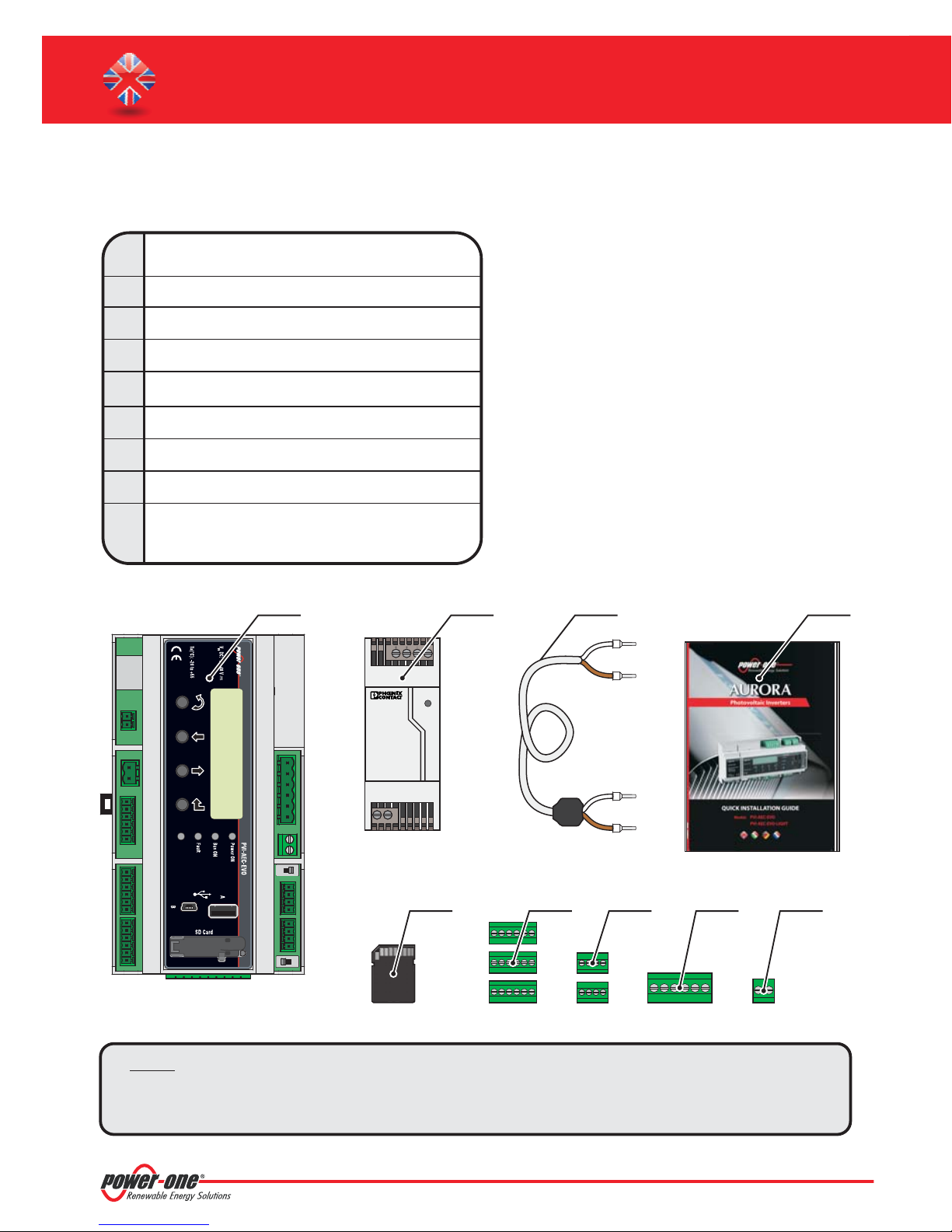
B. Package content
1
AURORA PVI-AEC-EVO / PVI-AEC-EVO LIGHT
2
Power Supply 100-240Vac 50-60Hz / 24Vdc
3
Power Supply connection cable
4
Quick Installation Guide
5
SD Card (assembled)
6
I/O Terminal Blocks Counterparts (assembled)
7
RS485 Terminal Blocks Counterparts (assembled)
8
Relais Terminal Blocks Counterparts (assembled)
9
Power supply Terminal Blocks Counterparts
(assembled)
1 2 4
STEP POWER
Input AC
100-240V
L(+) N(-)
3
--++
Output DC
24V 0.75A
DC
OK
5 6 7 8 9
Note: Checkthe packagecontentcorresponds totheabove list.
Pleasecheck thebox andeach singleitem insidehasno defect.In caseclaims tothe shippingcompany
andcommunicates quickly totheassistant technicalservice orto theCustomerserviceof Power-One.
3-EN
Monitoring System
C. User interface and use of the display
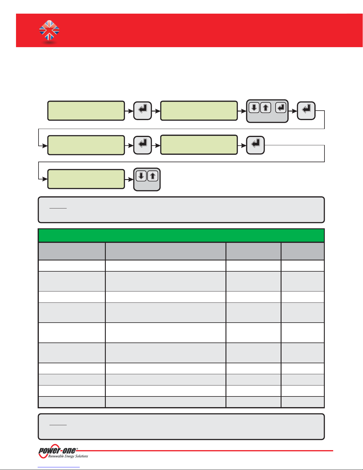
Thesystem featuresa 2x16character display,four buttonsfornavigating menus,and threeLEDsto indicatedevicestatus.
Usingthe displayand thebuttons onthe frontpanel itis possibleto perform theinitial configurationof thesystem(check
ofparameter acquisitionfrominverter,analog inputconfiguration,and configurationof LANnetworkparameters).
For displaying the detailed parameters of the inverters and/or of the string-combs, as well as for the advanced
configurationsit isnecessary toaccess theinternalweb serverfollowing theproceduredescribedin paragraph“L”.
Alist offunctions accessiblefromthe displayis shownin thetablein Appendix3.
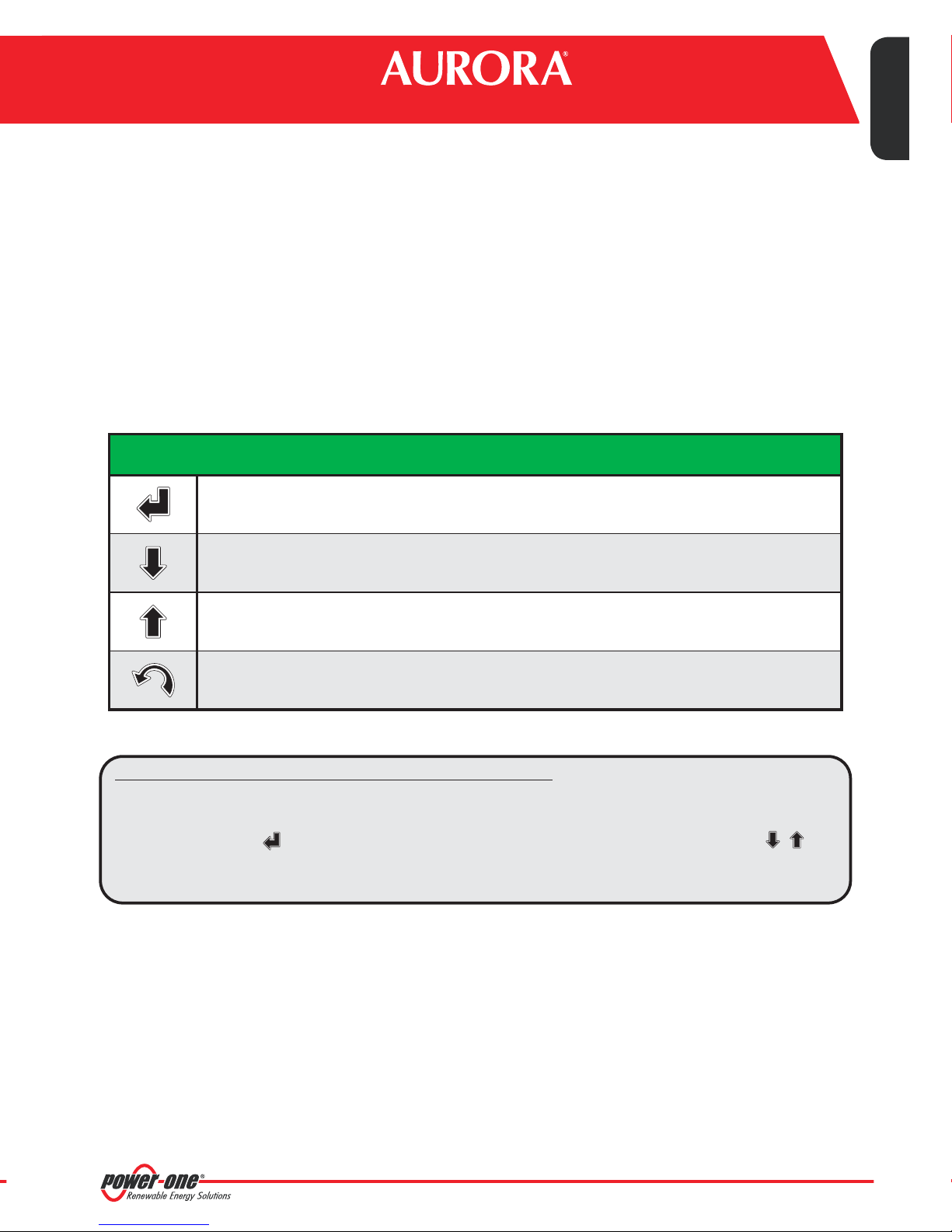
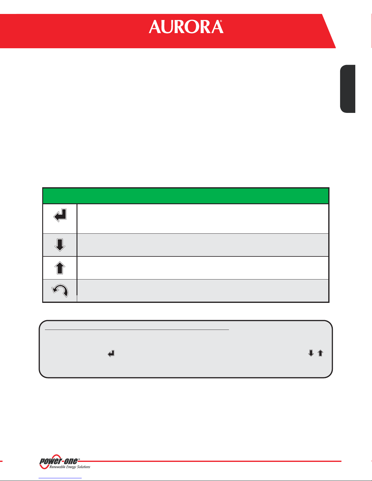
USE OF BUTTONS
'Enter' button. Used toconfirm an action,to accessthe main menuor the sub-menucorresponding to
theselectedentry(indicated bythe >symbol),orto gotothe nextdigit tochange.
'Down' button. Used to scroll down through the menu items, or to scroll the numerical scale in
descendingorder.
EN - ENGLISH
'Up' button. Used to scroll up through the menu items,or to scroll the numerical scale in ascending
order.
'Esc'button. Usedto returnto thepreviousmenu orto returnto thepreviousdigit tochange.
Accessto themain menu withadministratorprivileges
Toperformthe initialconfigurationit isnecessary toaccessthe variousdisplaymenus asadministrator.
Press the'ENTER' key ( ) and insert password : Toinsert the passwordpress the arrowkeys ( ) to
change thevalue and the'ENTER' key toconfirm the value. This passwordgives access toall the displaysetting submenusof thesystem.
0010
4-EN
PVI-AEC-EVO / PVI-AEC-EVO LIGHT
QUICK INSTALLATION GUIDE
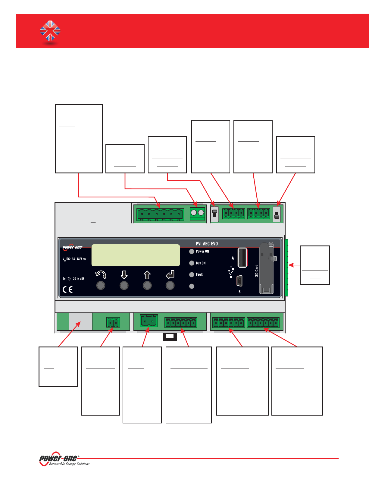
D. Pin-Out of System Connectors
Thediagram belowshowsthe pin-outof theconnectorswhich allowthesystem connection.
J5
RELAY
1) RELAY1-C
2) RELAY 1 - N.O
RELAY2-C
3)
4)
RELAY 2 - N.O
5)
RELAY3-C
6)
RELAY 3 - N.O
J12
GROUND
S2
120
Ω TERM.
RS485/1
J17
RS485/1
1) RTN
2) - T/R
3) +T/R
4) +5V
*
J15
RS485/2
1) RTN
2) - T/R
3) +T/R
4) +5V
S1
120
Ω TERM.
RS485/2
J7
LAN
IEEE802.3u
11122
J18
BATTERY IN
1) + Batt.
2) - Batt.
NOTE:
Only for dedicated
accessory
PVI-BATTERY-PACK
123456
J8
Vin DC
1) + Vcc
2) - Vcc
INPUT DC:
24 Vdc
(max. 48 Vdc)
0,3 A
NOTE:
Use the provided
power supply
5
3
6
4
J3
ANALOG INPUT
PT100/1000
1) PT_ALIM
2) PT_SENSE
3) PT_RTN
4) AIn_RTN
5) AIn 1
6) AIn 2
3
4
12
123456 1234562
J20
DIGITAL I/O
1) DO_RTN_PWM1
2) DO_ _PWM2
RTN
3) DO_PWM 1
4) DO_PWM 2
5) DIn 1
6) DIn_RTN
1234
J9
EXPANSION
BUS
J4
DIGITAL I/O
1) DIn 2
2) DIn 3
3) DIn 4
4) DIn_RTN
5) DIn 5 / CONT 2
6) DIn 6 / CONT 1
* In the PVI-AEC-EVO LIGHT model the RS458/1 port (J17) is not available as inverter communication port, but can be used only to
acquireparameters from powermeters equippedwith Modbuscommunicationinterface.ISKRAEMECO
5-EN

Monitoring System
E. Power Supply Connections and System Start Up
1. Connect the power supply to the power supply network (100/240V 50/60Hz): the "Power" led on the power
supply willlight up steadily.Check thatthe output voltageof the power supplyis 24Vdc.Disconnect the power
supplyfromthe powersupply network.
2. Connect theoutput of the powersupply tothe power supplyterminal blockof thePVI-AEC-EVO respecting the
polarity andusingthewiringprovided.
3. Connect thepower supplyto the powersupply network:After afirst starting phase(lasting about 30 seconds)
during whichthe systemis not able to receive anyinput from theuser,the green "PowerOn"led willremain lit.
The message“PVI-AEC-EVO...."(in the firstof the twolines) and date/time (in thesecond of the two lines)will
bedisplayed.
EN - ENGLISH
Output DC
24V 0.75A
DC
OK
STEP POWER
Input AC
100-240V
L(+) N(-)
L(+) N(-)
--++
12
+Vcc-Vcc
50-60 Hz
100-240 V~
Note: The system must be supplied with power supply and wiring provided; otherwise the CE
conformitywill notbe longervalid.
ONLY
6-EN

PVI-AEC-EVO / PVI-AEC-EVO LIGHT
QUICK INSTALLATION GUIDE
F. Date and time settings
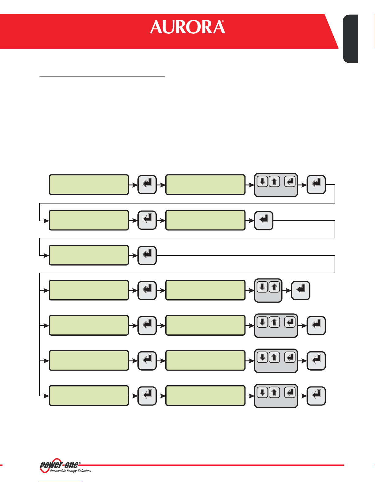
1. Enterthe mainmenu asadministrator (Seepar.'C’).
2. Access the menu and then select the sub-menu. This enables to set the
correctdatein thesystem.
3. Return to themenu and then selectthe sub-menu. This enablesto setthe correcttime
inthesystem.
'SETTINGS' > 'DATALOGGER' 'SET DATE'
'DATALOGGER' 'SET TIME'
SET PIN TO 0010
PVI-AEC-EVO ......
12.00.00 01/01/11
>settings
change password
>set date
set time
>set time
network
ENTER ENTER
ENTER
ENTER
ENTER ENTER
menu pin
0***
>datalogger
io settings
>set date
01/01/11
>set time
12.00.00
CHANGE VALUE
ENTER
CHANGE VALUE
CHANGE VALUE
NEXT
DIGIT
NEXT
FIELD
NEXT
FIELD
ENTER
G. Connection of the RS485 line and inverter acquisition
check
TheconnectionoftheRS485 linemust becarried outrespecting thepin-outs ofthe J15 and/orJ17connectors.
Note: For PVI-AEC-EVO LIGHT, the only usable RS485 port for inverter monitoring is the RS485/2,
correspondentto connectorJ15.
I
t is recommended to connect the RS485 line when all the equipment is switched off (both the monitoring system
andtheinverters)and tostartupthemonitoring systemfirst andthen theinverters. Itisrecommended to:
Use a cable for RS485 applications with the following characteristics: 1 twisted pair+1conductor or two
l
twisted pairs,Screen and characteristic Impedance equal to 120 . For further informationon the cableto be
usedreferto Appendix2.
Makesure thesignals correspond.
l
Makesure thatall threelines(+T/R,-T/RandRTN)are connectedaccording tothediagramsin pages9-10.
l
l
Makesure thatthe communicationlinescreenis groundedaccording tothediagramsin pages9 -10).
Make sure that each element in the chain (each inverter or each 55kW module) has a RS485 address that is
l
differentfrom theothers.This addresscan be setviathedisplayof theinverter.
Ω
7-EN

Monitoring System
Note: For PVI-AEC-EVO LIGHT, the inverters must be set with addresses: 1,2, 3, 4,5. The configuration of
address1 correspondsto"AUTO"settings asinverter address.
Note: When connecting multiple units (string inverter or/and 55kW conversion modules) it is necessary
towire theRS485 communicationline accordingtothe daisy-chaindiagram (enter-exit).
Thelast inverterof thedaisy-chain mustbe 'terminated'byactivating thetermination resistanceof
the 120 communicationline throughswitching thedip-switch located onthe motherboardin the
stringinverters,and insideeach frameworkof thecentralinverters.
Note: The maximum number of units (string inverters or/and 55kW conversion modules) that can be
connected to a RS485 port of the PVI-AEC-EVO is 62.In order to connect a number of unitsgreater
than 62it isnecessary to usethe secondRS485/2 port respectingthe samewiring diagram usedfor
themain RS485/1port.
Ω
EN - ENGLISH
In the PVI-AEC-EVO LIGHT the number of inverters that can be acquired is limited to a maximum of 5
strings inverters which can be connected by RS485/2 (Ref. Par.D). Compatible models (in every their
variation) for the PVI-ACE-EVO LIGHT version are: PVI-2000(-OUTD); UNO-2.0/2.5-I-OUTD; PVI-3600;
PVI-3.0/3.6/4.2-TL-OUTD; PVI-3.8/4.6-I-OUTD; PVI-5000/6000-TL-OUTD; PVI-10.0/12.5-TL-OUTD;
PVI-10.0/12.0-I-OUTD.
Note: In case of mixed systems, the presence of both string inverters and central inverters on the same
RS485line ispermitted.Towire thisline followall thedirections above.
Note: All string inverters (except for models PVI-5000/6000-TL-OUTD) have a clamp that allows giving
continuityto thecable shieldofthe RS485line.
For single-phase inverters this clamp is indicated by the words LNK, for three-phase inverters it is
indicatedby SCLD.
Note: The centralized inverters have a clamp, which is located in the signal terminal block and marked
with “X23”, that allows to link to ground theshield of each singular portion of the communication
line independentlyfrom the other portionof communication line.(must notbe given continuity to
thecable shield).
Note: For further details on the wiring of the RS485 line and/or the activation of the termination
resistances,refer totheuser manualof stringinverters andtothe usermanual ofcentralinverters.
8-EN
PVI-AEC-EVO / PVI-AEC-EVO LIGHT
QUICK INSTALLATION GUIDE
-T/R
+T/R
RTN
1234
Note: Make sure that each
inverter in the chain has a RS485
address that is different from the
others. For PVI-AEC-EVO LIGHT,
the inverters must be set with
addresses: 1, 2, 3, 4, 5. The
configuration of address 1
corresponds to "AUTO" settings as
inverteraddress.
AURORA
AURORA
ON
Ω
120 TERM.
RESISTOR
Ω
ON
OFF
120
Term.
Resistor
-T/R
+T/R
RS485
RTN
Ω
ON
OFF
120
Term.
Resistor
-T/R
+T/R
RS485
RTN
OFF
12
3
4
ON
-T/R
+T/R
RTN
Ω
RESISTOR
120 TERM.
RS485
OFF
Ω
120 TERM.
RESISTOR
RTN +T/R -T/R
AURORA
ON
Ω
ON
OFF
120
Term.
Resistor
-T/R
+T/R
RS485
RTN
OFF
-T/R
+T/R
RTN
Ω
RESISTOR
120 TERM.
RS485
-T/R
+T/R
ON
Ω
120 TERM.
RESISTOR
RTN
9-EN

Monitoring System
EN - ENGLISH
Note: Make sure that each
OFF
Ω
120 TERM.
RESISTOR
55 kW module in the chain
has a RS485 address that is
1234
12
3
4
ON
Ω
120 TERM.
RESISTOR
-T/R
+T/R
RTN
different from the others.
X20 X21 X22 X23 X24 X25 X26 X27
A
D
OFF
Ω
120 TERM.
RESISTOR
ON
Ω
120 TERM.
RESISTOR
X20 X21 X22 X23 X24 X25 X26 X27
A
D
RTN +T/R -T/R
D
X20 X21 X22 X23 X24 X25 X26 X27
A
D
-T/R
+T/R
RTN
D
X20 X21 X22 X23 X24 X25 X26 X27
A
X20 X21 X22 X23 X24 X25 X26 X27
A
10-EN

PVI-AEC-EVO / PVI-AEC-EVO LIGHT
QUICK INSTALLATION GUIDE
After carrying out these checks, start up first the monitoring system and then the inverters. The system automatically
carries outa scan ofthe RS485 busand automaticallydetects theavailable inverters.Thepresenceof the inverterscan be
checkeddirectly fromthedisplay.
1. Enter themainmenu asadministrator(Seepar.'C’).
2. Access the menu (to displaythe string inverters) and/or
'ENERGY RACK'
'CURRENTVALUES'> 'ENERGY INVERTERS' 'CURRENTVALUES'>
(to displaythe 55kW conversionmodules). The numberof inverters detected duringthe scan will be
displayed;the listof themonitoredinverters identifiedby theSerialNumber (S/N)can bedisplayedby scrollingusing
thearrow keys( ).
SET PIN TO 0010
PVI-AEC-EVO ......
12.00.00 01/01/11
>CURRENT VALUE
SETTINGS
>ENERGY INVERTERS
ENERGY RACK
>ENERGY RACK
ENERGY PLANT
ENTER ENTER
ENTER
ENTER
ENTER
menu pin
0***
30 INVERTERS
>INVERTER SN 123456
RACK N. 1
>RACK SN 123456
CHANGE VALUE
CHANGE
INVERTER
CHANGE
RACK
NEXT
DIGIT
Note: The time necessary for the PVI-AEC-EVO to scan and acquire the inverters depends on the number of
inverterspresent onthe sameline (sometimesseveral minutes).
H. Configuration of the Analog Inputs
Theconnection ofthe analoguesensors mustbe carriedoutrespecting thepin-outs ofthe J3connector.
Thesystem hastwo0-10Vdc inputsand aPT100/1000input.
Note: To eachanalogue input(both 0-10Vdc and PT100/1000types) it ispossible toconnect only oneanalog
sensor. It istherefore notpossible toconnect multiplesensors onthe sameanalog input.
With respect tothe connection ofthe PT100/1000 sensors,the system isable tocarry outthe sensor readingthrough the
connectionof three-wires:
Asensor powersupplyline (PT_ALIM);
l
Areading line(PT_SENSE);
l
Apower supplyandreading closingline(PT_RTN).
l
11-EN

Monitoring System
The measurement is carried outbetween PT_SENSE and PT_RTN,therefore the element to be measured must bewired
betweenthese twosignals.
The PT100/PT1000 sensor is automatically recognised by the system and is therefore acquired without the need for
further settings.
Regarding theconnection of the sensorswith output range0...10Vdc,these mustbe powered andthe power supplycan
be taken directly from the system power supply; the grounding of the power supply and the grounding of the signal
readingis thesame.
For the sensor connection, beside the power supply, it is necessary to connect the signal proportionally to the quantity
measuredat oneofthe twoanaloginputsavailable(Aln1/Aln2).
Thegrounding ofthe signal to bemeasured (ifdifferentfrom thegrounding ofthe powersupply –within thePower-One
sensorrange onlyin thewind speedsensor PVI-AEC-WIND-COMPACT) mustbe connectedto theAln_RTN clamp.
After carrying out the connections it is necessary to configure the sensor in the system so that the correct quantity is
acquired:
1. Enter themainmenu asadministrator(Seepar.'C’).
EN - ENGLISH
2. Access themenu .
3. Select the item and then select the sensor model connected tothe AIn1 input of the system (the
'SETTINGS' >'IO SETTINGS'
“ANALOG INPUT1”
selectedmodel willbe identifiedwithan asterisk(*)).
4. Select the item and then select the sensor model connected to the AIn2input of the system (the
“ANALOG INPUT2”
selectedmodel willbe identifiedwithan asterisk(*)).
Note: Incase ofconnecting PT100/1000 sensorswith onlytwo terminals,connect a terminalto thePT_SENSE
clampand aterminalto thePT_RTN clamp,thenmake ajumper betweenPT_ALIM andPT_SENSE.
SET PIN TO 0010
PVI-AEC-EVO ......
12.00.00 01/01/11
>settings
change password
ENTER ENTER
ENTER
menu pin
0***
>io settings
UPGRADE FIRMWARE
CHANGE VALUE
ENTER
NEXT
DIGIT
>ANALOG INPUT1
ANALOG INPUT2
>ANALOG INPUT2
PULSE IN1
ENTER
ENTER
>ANALOG INPUT1
T1000-INTEGR *
>ANALOG INPUT2
RAD-13TC *
12-EN
CHANGE
SENSORS
CHANGE
SENSORS
ENTER
ENTER
PVI-AEC-EVO / PVI-AEC-EVO LIGHT
QUICK INSTALLATION GUIDE
Toreadthe measurementsof thesensors andtochecktheiraccuracy followthe instructionsbelow:
1. Enterthe mainmenu asadministrator (Seepar.'C’).
2. Access the menu . The quantity value will be displayed for each of the
analoginputs.
PVI-AEC-EVO ......
12.00.00 01/01/11
>CURRENT VALUE
SETTINGS
>T1000-INTEGR AN1
20.0 DEGC
'CURRENT VALUES' > 'ANALOG VALUE'
menu pin
ENTER ENTER
ENTER ENTER
CHANGE
INPUT
0***
>ANALOG VALUE
DIGITAL VALUE
SET PIN TO 0010
CHANGE VALUE
NEXT
DIGIT
Note: In the following table it is reported a list of the sensor which are present in thecatalogue “Power-one”.
Forthe connection ofthese sensors,please makereference todiagrams showninAppendix 1.
SENSORS WITH ANALOG OUTPUTS COMPATIBLE WITH PVI-AEC-EVO (POWER-ONE CATALOGUE)
MODELL TYPE
PVI-AEC-IRR
Radiation sensor (W/m --> V)
PVI-AEC-IRR-T Radiation sensor with integrated cell
temperature sensor
PVI-AEC-RAD-13TC
PVI-AEC-RAD-13TC-T
Radiation sensor (W/m --> V)
Radiation sensor with integrated cell
temperature sensor
2
2
(W/m --> V)
/°C
2
2
(W/m --> V)
/°C
DISPLAY
IDENTIFICATION CODE
IRR
IRR-T_Irr /
IRR-T_Temp
RAD-13TC
RAD-13-TC-T_Irr /
RAD-13-TC-T_Temp
OPERATIVE
RANGE
0-1200 W/m
0-1200 W/m
-20 to +80 °C
0-1300 W/m
0-1300 W/m
-25 to +90 °C
2
2
2
2
PVI-AEC-T100-ADH
Adhesive module temperature sensor
(back cell) PT100
PVI-AEC-T1000-INTEGR
Ambient temperature sensor connected to
PT100/0...10Vdc converter (°C --> V)
PVI-AEC-T1000-BOX
PVI-AEC-PYR-1300
PVI-AEC-WIND-COMPACT
PVI-AEC-WIND-DIR
Ambient temperature sensor PT100
Pyranometer ( --> V)W/m
Wind speed sensor (m/s --> V)
Wind direction sensor (° --> V)
Note: The system is predisposed for the connection to other sensors available: ZippZonen Pyranometer 0-
1600W/m and
2
Pyranometer0-2000W/m .
T100-ADH
T1000-INTEGR
T1000-BOX
2
Pirano_0-20mA
WIND-COMPACT
WIND-DIR
2
13-EN
-50 to +150 °C
-50 to +50 °C
-50 to +50 °C
0-1300 W/m
2
0-50m/s
0 - 360°
Monitoring System
I. System Configuration for connection to the LAN
Network (Ethernet Port)
The connectionto the PCof PVI-AEC-EVOcan bemade through directconnection viaEthernet cable,or connecting
bothdevicesto alocal networkLAN (viarouter,hub orswitch).
Incase of direct connection,it isenough toconnect thetwo devicesbetween themthrough aEthernet cable andset
thenetworkparameters ofPVI-AEC-EVO andof thePC tomakesure theyare compatiblebetweenthem.
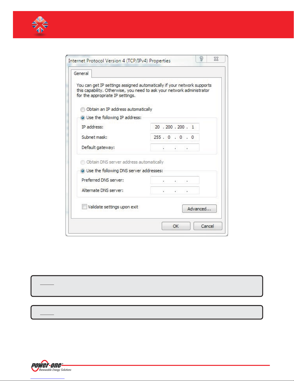
Note: The IPaddress of the PCand the IP addressof the PVI-AEC-EVO must belongto the same groupbut
they ,for instance:
mustnot beidentical
PC IP ADDRESS:
PVI-AEC-EVO IP ADDRESS:
The subnet mask must be the same for both devices, for instance: 255.0.0.0
Incase ofconnection toa pre-existinglocal networkLAN,itisnecessaryto assignto PVI-AEC-EVOthe networkparameters
which have to be compatible with the local network to which the PVI-AEC-EVO is connected. Make reference to the
networkadministrator toobtain thecorrect parametersof thenetwork.
20.200.200.
20.200.200.
1
24
EN - ENGLISH
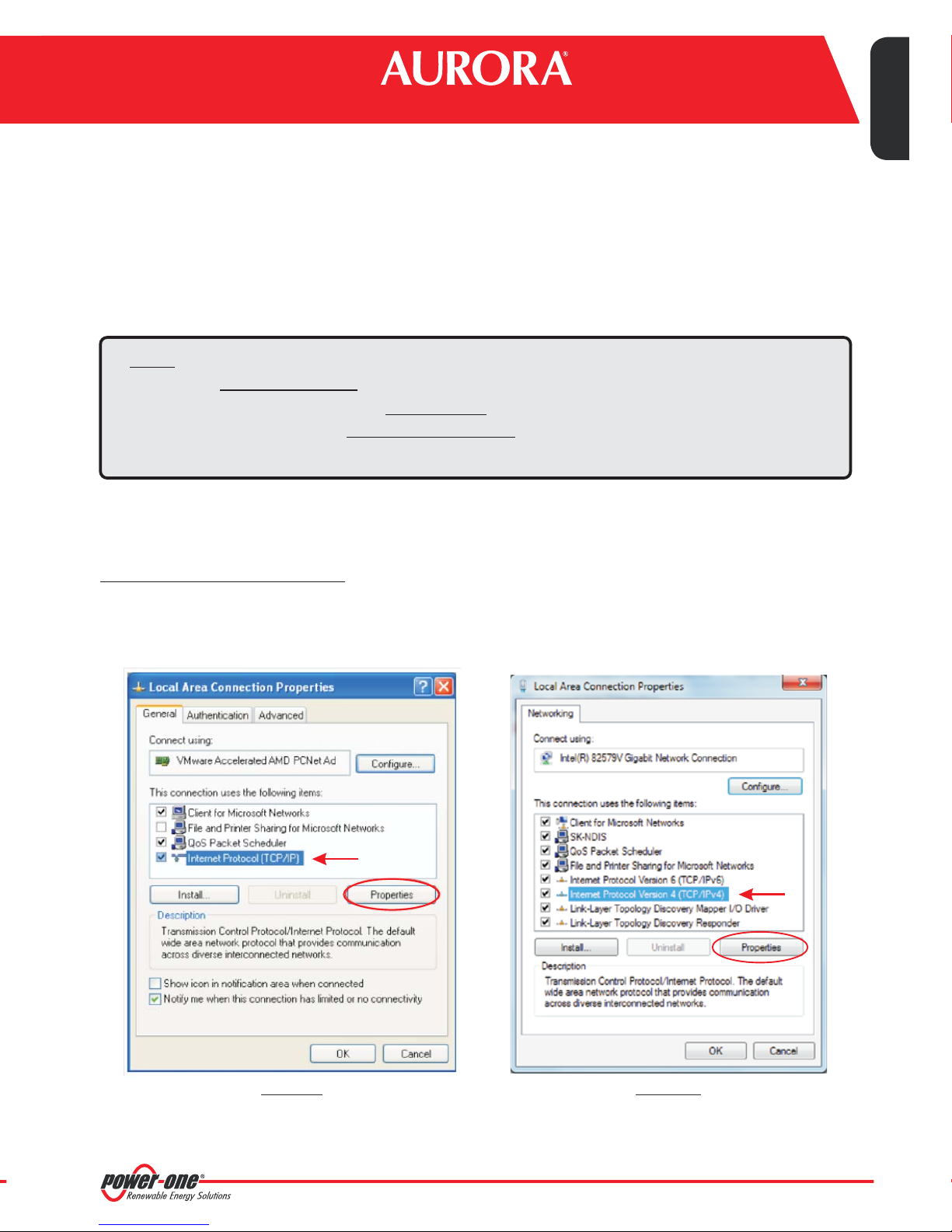
CHANGEOF PCNETWORK PARAMETERS
In order to change pc network parameters, please select and then click on
Connections”
“LocalArea Connection” “Properties”
: the new window will show the network connections; with the right button of your mouse click on
andselect ;asshowninthe followingfigure.
“Start” “Control Panel”, “Network
Windows XP Windows 7/8
Select (or in Windows 7/8) and click on“Internet Protocol (TCP/IP)” “Internet Protocol Version 4 (TCP/IPv4)”
“Properties”.
14-EN
PVI-AEC-EVO / PVI-AEC-EVO LIGHT
QUICK INSTALLATION GUIDE
Select the option and insert the network parameters (IP address, Subnet Mask,
“Use the following IP address”
Gateway)compatible withthe networkparametersset inthe PVI-AEC-EVO.
DNSparametersfields canbe letempty.
Note: In case of direct connection between PVI-AEC-EVO and PC we suggest not to set “Gateway”
parameters.
Note: Thistype ofprocedureis tobe consideredonly anexample forthe mostpopularoperating systems.
15-EN
Monitoring System
CHANGETHEPVI-AEC-EVONETWORK PARAMETERS
:in ordertochange thePVI-AEC-EVOnetworkparameters,please followthe procedurebelow:
Poweron thesystemandwaitfor thestartupphaseto complete(Ref.Par.'E’).
1.
Enterthe mainmenu asadministrator (Ref.Par.'C’).
2.
3. Access themenu .
“SETTINGS” > “NET WORK ”
Subnet mask,Gateway)may bemodified using the items ofthe menu.This allowsto configure the
systemfor connectionto theLAN networkand/or fordirectconnectiontoaPC.
4. At the end of the setting operations, return to the main screen, then switch off and switch on the system to
makethe settingstake effect.
The parametersfor connection to theLAN network (IP address,
"NETWORK"
SET PIN TO 0010
EN - ENGLISH
PVI-AEC-EVO ......
12.00.00 01/01/11
>settings
change password
>NETWORK
SET DATA
>IP method
ip setting
>IP SETTING
SUBNET MASK
>SUBNET MASK
ip gateway
menu pin
ENTER ENTER
0***
CHANGE VALUE
NEXT
DIGIT
>datalogger
ENTER
ENTER
io settings
ENTER
>IP method
ENTER ENTER
manual
CHANGE
METHOD
>IP SETTING
ENTER ENTER
XXX.XXX.XXX.XXX
CHANGE VALUE
NEXT
DIGIT
>subnet mask
ENTER ENTER
XXX.XXX.XXX.XXX
CHANGE VALUE
NEXT
DIGIT
>IP gateway
ip method
>IP gateway
ENTER ENTER
XXX.XXX.XXX.XXX
16-EN
CHANGE VALUE
NEXT
DIGIT

PVI-AEC-EVO / PVI-AEC-EVO LIGHT
QUICK INSTALLATION GUIDE
L. Internal Webserver access
In order to access to the Webserver pages of the system, after having done the connection of the system to the local
network LAN or direct connection to the PC, open an internet browser (e.g. Internet Explorer) and type into the
addressbar thefollowing address:
Note: Toaccess thewebserver pagesitis necessaryto inserta usernameand apassword:
USERNAME: admin PASSWORD: admin
After having done the access to the internal Webserver, go to the configuration page (CONFIG) of the system
(PLANT) andinserttheinstallationGPS coordinatesaccordingto oneof thefollowingformats:
Indicator Degrees Point Degrees (Hundredths of degree)
Latitude
Longitude
N43.33
E11.35
http://<system IP address>
N43 . 33
E11. 35
Degrees Indicator
Latitude
Longitude
*
The Double Quotation Mark ( ”) symbol must be inserted by entering twice the quotation mark(')symbol.
43N50’20”
11E23’30”
43
11
N
E
Minutes Quotation Mark Seconds Double quotation mark*
50
23
‘
‘
20
30
“
“
Note: Toset theGPS parameteris mandatoryto assurethe properworking ofmonitoring system.
17-EN

Monitoring System
Inordertoallow thePVI-AEC-EVOtocommunicate withthe AuroraVision webportal,accesstheconfigurationpage
(CONFIG) of the network (NETWORK) and check that in section 'DATA TRANSFER', under item 'IP Address Portal'
thereis theIP address .63.236.63.180
Note: If the setting 'IP Portal Address' does not correspond to 63.236.63.180, change it by entering the
above-mentioned address and press 'Confirm' to activate it. After this operation,reset the system
(ON-OFF).
Note: To make the system fully functioning it is essential that the same system is constantly connected
to the internet so that it is able to communicate with the Power-One server. This is essential to
graphicallyshows the dataon web pagesas wellas for sendingalarm and/or report messages.It is
essential that the LAN network in which the PVI-AEC-EVO is wired is such that it allows the
connection to the IP address 63.236.63.180 to be reached through port 80, so that the
PVI-AEC-EVO is ableto communicatewith theportal managementserver.
EN - ENGLISH
18-EN

PVI-AEC-EVO / PVI-AEC-EVO LIGHT
QUICK INSTALLATION GUIDE
19-EN

Monitoring System
M. MAC Address Identification
During the process of associationof PVI-AEC-EVO in AuroraVision you will beprompted toenter the MAC addressof the
PVI-AEC-EVOpresent inthesystem.
Itis possibletoobtain theMACAddressofyourPVI-AEC-EVO observingthe labelonthe rightside ofthe product.
TheMAC Addressis composedof12 characters(separatedby acolon)shownin red for examplein thefigure below.
PVI-AEC-EVO
P-1 P/N: 3I72001F100G Prod. Week 16/11
S/N: 3I72001F100G 000464VI1611
EN - ENGLISH
MAC ADDRESS: 00:50:C2:42:38:24
Alternativelyit's possibleto obtainthe MACAddress fromthe display:
1. Enter themainmenu asADMINISTRATOR(refer topar.“C”)
2. Enter the menu.
3. Using thearrowbuttons ( )moveto view
PVI-AEC-EVO ......
12.00.00 01/01/11
>INFORMATION
“INFORMATION” > “PRODUCT”
CURRENT VALUE
pN
3I72
“MACADDRESS” .
menu pin
ENTER ENTER
ENTER ENTER
CHANGE
MENU
0***
>PRODUCT
NETWORK
MAC ADDRESS
00:50:C2:42:38:24
SET PIN TO 0010
CHANGE VALUE
NEXT
DIGIT
20-EN

PVI-AEC-EVO / PVI-AEC-EVO LIGHT
QUICK INSTALLATION GUIDE
O. Firmware updating procedure via SD Card
It is possible to upgrade the firmware of the PVI-AEC-EVO either locally using the SD Card, or remotely using the web
portal AuroraVision.
Note: The firmware update via SD card should be carried out.only if it is not possible to update the firmware
viathe AuroraVision webportal
Note: For detailson theprocedure forthe firmware updatingthrough theweb portal AuroraVision,refer
tothe documentationon thewebsite .www.Auroravision.net
1. Access thedisplay byenteringthe userpassword0000.
2. Check andnotethe currentfirmwareversions installed:
FirmwareAVR: Information > Product > FirmwareAVR
FirmwareDisplay:
FirmwareIO:
3. Turnoff thePVI-AEC-EVOand waitatleast oneminute.
4. Disconnect allavailableconnections fromthePVI-AEC-EVO(RS458 line(s),LANconnection,sensors).
5. Remove theSD Cardfromthe slotonthePVI-AEC-EVO frontpanelby pressingtheSD Cardgently.
6. Insertthe SDCardinto theSDCard readerorinto totheSD Cardreaderslot ofthePC.
7. Delete thefoldersupgrade,web,langand configfromthe SDCard.
8. Copythe newfolders upgrade,web,lang andconfiginto therootof theSDCard.
9. Remove theSD Cardfromthe SDCardreader orfromthe SDCardreader slot.
10. Insert theSDCard intotheslot onthe PVI-AEC-EVOfront panelbypressing theSD Cardgently tolockit intoplace.
11. Turnon the PVI-AEC-EVOand wait aboutone minute.(N.B.: Powerfailure duringupdatemay cause seriousdamage
tothe device).
12. Enterthe displaybypushing theENTER buttonand insertthe password“0010”;push ENTERto confirm.
13. Followthe path: pressENTER to confirm;wait thecompleting of
upgrade(fewminutes).After theupgrade thesystemwill reboot:wait thecomplete reboot (date/timewill beshown
onthe display).
“SETTINGS > UPGRADE FIRMWARE> UPGRADE AVR”
Information > Product > FirmwareDisplay
Information > Product > FirmwareIO
14. Enterthe displaybypushing theENTER buttonand insertthe password“0010”;push ENTERto confirm.
15. Follow thepath press ENTERto confirm;wait thecompleting of
upgrade (few minutes). The upgrading process will be completed when the message will be
displayed.
“SETTINGS > UPGRADE FIRMWARE > UPGRADE ADC”
“Upgrade Success”
21-EN

Monitoring System
EN - ENGLISH
16. Followthe path pressENTER toconfirm;waitthe completing
of upgrade (few minutes).The upgrading process will be completed when the message will be
“SETTINGS >UPGRADE FIRMWARE>UPGRADE DISPLAY”
“Upgrade Success”
displayed.
17. Follow the path press ENTER to confirm; wait the completing of upgrade (few
minutes).The upgrading process will be completed when the message will be displayed again.
“SETTINGS > UPGRADE CONFIG”
“UPGRADE CONFIG”
PressESC toexit.
18. Switchoff thesystem,restoreallconnections (RS485line(s),LANconnection,sensors),thenswitchon thesystem.
22-EN

PVI-AEC-EVO / PVI-AEC-EVO LIGHT
GUIDA DI INSTALLAZIONE RAPIDA
INDICE
A. Descrizione del prodotto 2
B.
C.
D.
E.
F.
G.
H.
I.
L.
M.
Contenuto della confezione
Interfaccia Utente ed utilizzo del display
Piedinatura dei connettori del sistema
Collegamento dell’alimentazione del sistema
Impostazione di data ed ora
Collegamento della linea RS485 e verifica dell’acquisizione degli inverter
Configurazione degli ingressi analogici
Configurazione del sistema per la connessione in rete LAN (porta Ethernet)
Accesso alWebserver interno
Identificazione del MAC Address
3
4
5
6
7
7
11
14
17
20
N.
Aggiornamento Firmware
Appendici
1) Schemi di collegamento sensori
2) Caratteristiche cavo RS485
3) Display flow-charts
4) Requisiti di conformità
21
1-IT

Monitoring System
A. Descrizione del Prodotto
I sistemiPVI-AEC-EVO ePVI-AEC-EVO LIGHT sonosistemi dimonitoraggio e controllo degliimpianti fotovoltaicirealizzati
conprodotti Power-One. Nel seguitosi faràriferimento al"sistema" intendendoentrambe leversioni diprodotto,mentre
verràspecificato ilmodello nelcaso incuile lorocaratteristichesiano differenti.
Il prodottoconsente l'acquisizionedei parametri dainverter e stringcomb (secondol'architettura dimonitoraggio
degliinvertercentralizzati) attraversolineaRS485conprotocollo proprietarioPower-One.
Il sistemadispone di due porte RS485(equivalenti traloro) che permettono l'acquisizione,ciascuna, di 62 inverter
di stringa o di 62 moduli di conversione da 55kW (inverter centralizzati modulari); E’inoltre possibie utilizzare la
porta di comunicazione RS485/1 (rif. capitolo D) per l’acquisizione di parametri da contatori ISKRAMECO MT831
dotatidi interfacciacomunicazioneModbus.
Nota: Nella versione PVI-AEC-EVO LIGHT il numero di inverter monitorabili è limitato ad un massimo di 5
inverterdi stringa,collegabili unicamentealla portaRS485/2 (Rif.Par.D). I modellicompatibili (intutte
leloro varianti)sono iseguenti:
PVI-2000(-OUTD) UNO-2.0/2.5-I-OUTD PVI-3600
IT - ITALIANO
PVI-3.0/3.6/4.2-TL-OUTD* PVI-3.8/4.6-I-OUTD PVI-5000/6000-TL-OUTD*
PVI-10.0/12.5-TL-OUTD* PVI-10.0/12.0-I-OUTD
(*): La compatibilitàè estesaanche alleprecedenti versioninazionali ( Es: PVI-3.6-OUTD-IT )
Nella versionePVI-AEC-EVO LIGHT la porta di comunicazione RS485/1(Rif. Par.D) può essere utilizzata
unicamente per l’acquisizione di parametri da contatori ISKRAMECO MT831 dotati di interfaccia
comunicazioneModbus.
Il sistema dispone di tre ingressianalogici per il collegamento di sensori per lamisura dei parametri ambientali:PowerOne offre, a catalogo, una gamma completa di sensori di irraggiamento, temperatura ambiente e di cella, velocità e
direzionedel vento.
Ilsistema metteadisposizione anchesei ingressidigitaliper l'acquisizionedi segnalidistato (adesempiocontatti ausiliari
diinterruttori dipotenza)a cuisonoassociatecondizionidiallarme distato.
Relativamente all'interfaccia utente, il sistema dispone di un display 2x16 caratteri e quattro pulsanti oltre che di un
webserverintegrato dipaginehtml accessibileattraversoconnessione LAN.
La configurazione iniziale del sistema (verifica dell'acquisizione dei parametri da inverter,configurazione degli ingressi
analogici,configurazione deiparametri direte LAN)puòessere eseguitainteramenteattraverso ildisplayed ipulsanti;per
la visualizzazione dei parametridi dettaglio degli inverter e/o dellestringcomb nonchè per le configurazioni avanzate è
necessarioaccedere allepaginedi webserverintegrato.
Il PVI-AEC-EVOlavora inabbinamento al servizio diportale web AuroraVision: effettuando laregistrazione a taleservizio
saràpossibile effettuareilmonitoraggio elagestioneda remotodegli impiantiassociati alproprio account.
Ilportaleweb AuroraVision èdisponibilealla paginaweb: www.Auroravision.net
2-IT

PVI-AEC-EVO / PVI-AEC-EVO LIGHT
GUIDA DI INSTALLAZIONE RAPIDA
B. Contenuto della confezione
1
AURORA PVI-AEC-EVO / PVI-AEC-EVO LIGHT
2
Alimentatore 100-240Vac 50-60Hz / 24Vdc
3
Cablaggio connessione alimentatore
Guida di installazione rapida
4
SD Card (assemblata)
5
Controparti morsettiere I/O (assemblate)
6
Controparti morsettiere Rs485 (assemblate)
7
Controparte morsettiera Relè (assemblata)
8
Controparte morsettiera Alimentazione
9
(assemblata)
1 2 4
--++
Output DC
24V 0.75A
DC
OK
STEP POWER
Input AC
100-240V
L(+) N(-)
3
5 6 7 8 9
Nota: Verificareche ilcontenutodella confezione corrispondaalla listadicui sopra.
Controllare inoltre che non vi siano danneggiamenti alla confezione, al dispositivo e agli accessori in
corredo. In caso di non conformità si consiglia di presentare reclamo presso la ditta di trasporti e di
comunicaretempestivamenteal servizio diassistenza tecnicaoppureal customerservice di Power-One
ladifformità riscontrata.
3-IT
Monitoring System
C. Interfaccia Utente ed utilizzo del display
Il sistemadispone di un display 2x16 caratteri,quattro pulsantiper la navigazione neimenu e tre LEDche indicano
lostatodel dispositivo.
Attraversol’uso del display edei pulsantiposti sulpannello frontaleè possibile effettuarela configurazioneiniziale
del sistema (verifica dell'acquisizione dei parametri da inverter, configurazione degli ingressi analogici,
configurazionedei parametridi reteLAN).
Per la visualizzazione dei parametri di dettaglio degli inverter e/o delle stringcomb nonchè per le configurazioni
avanzateè necessarioaccedereal webserverinterno seguendola proceduradescritta nelparagrafo“L”.
Unalista dellefunzioni accessibilida displayèmostrata nellatabella presentein Appendice3.
UTILIZZO DEI PULSANTI
IT - ITALIANO
Pulsante “Enter”. Viene utilizzato per accedere al menu principale o al
sottomenu corrispondente alla voce selezionata (indicata dal simbolo >), o per passare alla cifra
successivada modificare.
Pulsante“Down”. Viene utilizzato per scorrere le voci dei menu verso il basso, oppure per scorrere la
scalanumerica inordinedecrescente.
Pulsante“Up”. Viene utilizzato per scorrere le voci dei menu verso l’alto,oppure per scorrere la scala
numericain ordinecrescente.
Pulsante“Esc”. Viene utilizzato per tornare al menu precedente o per tornare alla cifra precedente da
modificare.
Accessoal menuprincipale conprivilegidiamministratore
Perpotereffettuare leconfigurazioniiniziali, è necessarioaccedere comeamministratoreai varimenu deldisplay.
Premereil tasto“ENTER”( ) edinserire lapassword : per inserirelapassword premerei tastifreccia( )
permodificare ilvaloreed iltasto“ENTER”perconfermare ilvalore. Attraversoquesta passwordè possibileaccederea
tuttii sottomenudiimpostazione delsistema dadisplay.
per confermare un’ azione,
0010
4-IT

PVI-AEC-EVO / PVI-AEC-EVO LIGHT
GUIDA DI INSTALLAZIONE RAPIDA
D. Piedinatura dei connettori del sistema
Loschema diseguito riportala piedinaturadei connettorichepermettonola connessionedel sistema.
J5
RELAY
1) RELAY1-C
2) RELAY 1 - N.O
RELAY2-C
3)
4)
RELAY 2 - N.O
5)
RELAY3-C
6)
RELAY 3 - N.O
J12
GROUND
S2
120
Ω TERM.
RS485/1
J17
RS485/1
1) RTN
2) - T/R
3) +T/R
4) +5V
*
J15
RS485/2
1) RTN
2) - T/R
3) +T/R
4) +5V
S1
120
Ω TERM.
RS485/2
J7
LAN
IEEE802.3u
11122
J18
BATTERY IN
1) + Batt.
2) - Batt.
NOTE:
Only for dedicated
accessory
PVI-BATTERY-PACK
123456
J8
Vin DC
1) + Vcc
2) - Vcc
INPUT DC:
24 Vdc
(max. 48 Vdc)
0,3 A
NOTE:
Use the provided
power supply
5
3
6
4
J3
ANALOG INPUT
PT100/1000
1) PT_ALIM
2) PT_SENSE
3) PT_RTN
4) AIn_RTN
5) AIn 1
6) AIn 2
3
4
12
123456 1234562
J20
DIGITAL I/O
1) DO_RTN_PWM1
2) DO_ _PWM2
RTN
3) DO_PWM 1
4) DO_PWM 2
5) DIn 1
6) DIn_RTN
1234
J9
EXPANSION
BUS
J4
DIGITAL I/O
1) DIn 2
2) DIn 3
3) DIn 4
4) DIn_RTN
5) DIn 5 / CONT 2
6) DIn 6 / CONT 1
* Nel modelloPVI-AEC-EVO LIGHTlaportaRS485/1 (J17)non èdisponibileper l’acquisizionedegli inverter,maè utilizzabileunicamente
perl'acquisizione diparametrida contatoriISKRAEMECO dotatidi interfaccia dicomunicazione ModBus.
5-IT

Monitoring System
E. Collegamenti di alimentazione del sistema
1. Collegarel'alimentatore allaretedi alimentazione(100/240V- 50/60Hz):il led“Power”dell'alimentatoresi accenderà
stabilmente.Verificare che la tensione di uscita dell'alimentatore sia 24Vdc. Scollegare l'alimentatore dalla rete di
alimentazione.
2. Collegare l'uscita dell'alimentatore alla morsettiera di alimentazione del PVI-AEC-EVO (rispettando la polarità)
utilizzandoil cablaggiofornitoa corredo.
3. Collegare l'alimentatore alla rete di alimentazione: dopo una prima fase di avvio (della durata di circa 30
secondi), durante la quale il sistema non è in grado di ricevere input da parte dell'utente, il led verde“Power ON”
rimarrà stabilmenteacceso.A display saràvisibile la scritta“PVI-AEC-EVO....”(nella prima delledue righe) edata/ora
(nellaseconda delleduerighe).
IT - ITALIANO
Output DC
24V 0.75A
DC
OK
STEP POWER
Input AC
100-240V
L(+) N(-)
L(+) N(-)
--++
12
+Vcc-Vcc
50-60 Hz
100-240 V~
Nota: Il sistema deve essere alimentato con l'alimentatore ed il cavo fornito a corredo, pena il
decadimentodella certificazione CE.
unicamente
6-IT
 Loading...