

INSTALLATION
&
OPERATING
INSTRUCTIONS
Approval No. 7978
Australian Patent
PN 200110001S
Effective January 2013
Serial Number: B.D. Number:
Model: IS900
Aurora
CLIMATE SYSTEMS
A.B.N. 43 108 083 987
PLEASE KEEP THESE
INSTRUCTIONS FOR
FUTURE REFERENCE

1
TABLE OF CONTENTS
SAFETY LABEL
To The New Owner 2
Safety Labels 3-4
INSTALLATION INSTRUCTIONS
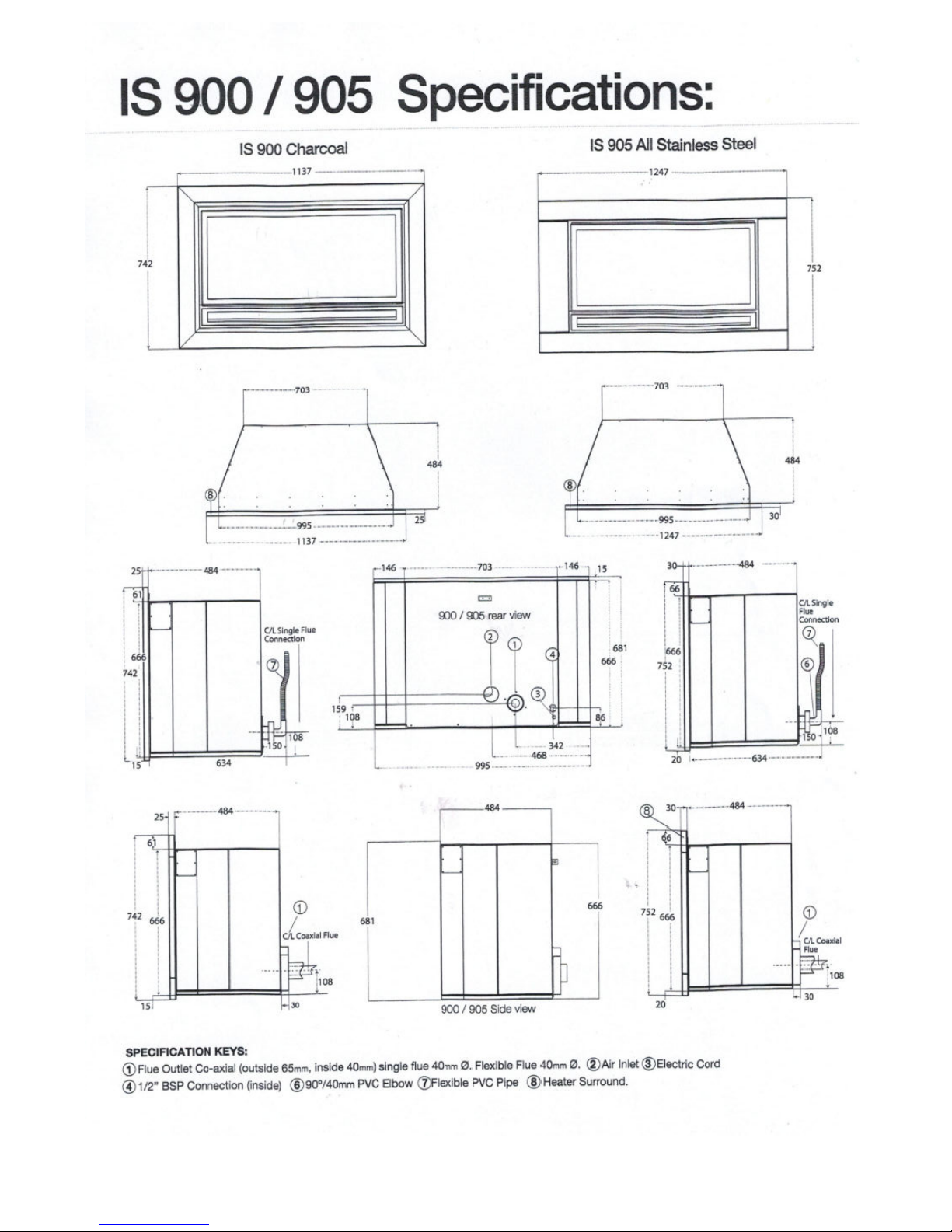
Specifications 5
General Safety Information 6
Clearances to Combustibles 7
Log Installation 8-9-10
Door Fitting 11
Surround 12-13
Flue options 14-16
Single Flue Installation 17-21
Co Axial Flue Installation 22-23
Optional remote control 24-25
Wiring Diagram 26-27
Gas Connections 28-29
Main door installation 30
OPERATING INSTRUCTIONS
Automatic Humidifier Operation 31
Operating Instructions Checklist 32-33
Lighting Instructions 34-36
Fan Operation 37-38
Shutdown Instructions 39
MAINTENANCE 40
Gold/Chrome Plated Doors 41
Glass Replacement/Cleaning 41
FREQUENTLY ASKED QUESTIONS 42-44
TROUBLE SHOOTING CHECKLIST 45-46
COMPLETE UNIT WARRANTY 47-48
NOTES 50
TO THE NEW OWNER
Congratulations! You are the owner of a state of the art Archer High Efficiency Gas Log Space Heater.
This appliance has been designed to provide you with all the warmth and charm of a wood fire at the flick of a
switch. The Archer Gas Log Space Heater promises to provide you with the highest economy, heat output, comfort
and security.
NOTE: AURORA WARRANTY PROGRAM
Please note to qualify for the Aurora Warranty Program, you need to fill out the warranty registration form,
and have your qualified installer fill out the Installation Commissioning Report. Both documents must be returned promptly to Aurora Climate Systems.
Under new government legislation, you also need to obtain from your qualified installer, a Certificate of Compliance for the guarantee of the installation.
Please note, that Aurora Climate Systems will not accept responsibility for faults with the appliance caused through
installation faults. We therefore strongly recommend that you return to Aurora Climate Systems the Installation
Commissioning Report and obtain a Certificate of Compliance from your qualified installer for your protection.
Failure to do so can void your warranty.
Please take a moment now to acquaint yourself with the instructions and many features of your Archer High
Efficiency Gas Log Space Heater.
Warranty - Installation - Service
(Listing and Code Approvals)
This appliance has been tested in accordance with AGA to code AS4553 Test Approval No. 7978G , and has been
certified to the Electrical AS3100 standard. Please keep these instructions in a safe place for future reference.
Check with your local council’s building department to ensure compliance with local codes, including the need for
permits and follow up inspections. Or if you wish clarification of the instructions contained in this manual, please
contact Aurora Climate Systems on telephone (03) 9795 8895 or facsimile (03) 9701 2088.
Note: As the Archer Gas Log Space Heater you have purchased is a high tech, high efficiency
appliance, we wish to advise that your appliance should at all times only be installed by a licensed Gas Fitter /
Installer for the installation and service of the Archer Gas Log Space Heater. No parts or functions should be
modified or permanently removed from the heater.
At no time should this appliance be installed outside the installation guide lines contained in the
Installation Manual, or by a non qualified gas fitter / installer. To do so will void the warranty.
It is policy of Aurora Climate Systems that should a fault develop in the Archer Gas Log Space Heater during its
warranty period, Aurora will repair the appliance in accordance with its warranty policy. However we wish to advise
that should the Archer Gas Log Space Heater develop a fault in its operation because the product was not installed
in accordance with the manufacturer’s guidelines and instructions, or if the product was not installed
correctly by a licensed gas fitter / installer or lack of operating knowledge of the appliance by the customer causing
appliance failure and Aurora is required to correct such faults, a service charge will apply.
In such cases, where attendance is required by Aurora Service Personnel to correct faults in the product which are
not directly related to the product and / or parts failure but are the result of improper installation and lack of
operating knowledge of the appliance, Aurora Climate Systems will charge the purchaser of the appliance and the
installer / service agent a fee calculated on the basis of $80.00 + GST per hour minimum, as well as travelling
expenses in excess of 25 km each way to rectify such faults.
2
Installation Requirements
SAFETY LABELS
DO NOT MODIFY THIS APPLIANCE
!
IMPROPER INSTALLATION,
ADJUSTMENT, ALTERATION, SERVICE OR
MAINTENANCE CAN CAUSE INJURY OR
PROPERTY DAMAGE. REFER TO THIS
M A N U A L F O R A S S I S T A N C E O R
ADDITIONAL INFORMATION, CONTACT
AURORA CLMATE SYSTEMS.
TELEPHONE NUMBER (03) 9795 8895
THIS APPLIANCE MUST BE INSTALLED OR
SERVICED ONLY BY A LICENCED GAS
F I T T E R
Note: If this appliance is installed by a licensed gas fitter who is not familiar on the
installation of the heater, we recommend that prior to installing the appliance the
installer contact Aurora to obtain further advice on the installation of the product.
FOR YOUR SAFETY
What to do if you smell gas?
1) Open Windows
2) Turn off main gas supply
3) Do not touch any electrical switches
4) Extinguish any open flames
5) Immediately call your gas supplier
or installer
Do not store or use gasoline or other
flammable vapors and liquids in the
vicinity of this or any other appliance
3
4
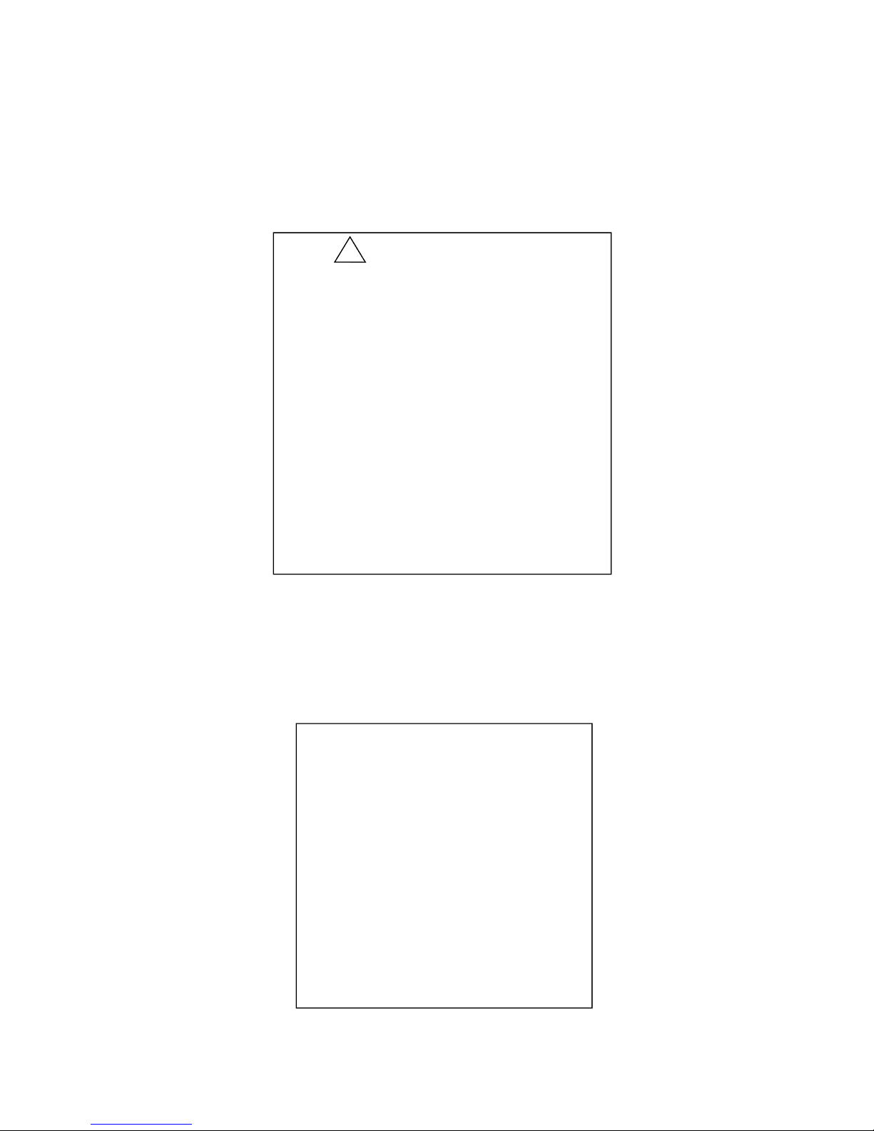
SAFETY LABELS
Air Pressure switch
Cut in Pressure
Cut out Pressure
Electrical Connection
Cleveland Controls / NS2.– XXXX-XX
138 Pa
120 Pa
2 Meter flex standard 3 Pin Plug
Note: In case of power cord damage, replace only with Archer special cord set, obtainable from your Archer
Dealer or direct from Aurora Climate Systems.
DO NOT OPERATE THIS APPLIANCE BEFORE READING THE
INSTRUCTION BOOKLET
DO NOT PLACE ARTICLES ON OR AGAINST THIS APPLIANCE
DO NOT STORE CHEMICALS OR FLAMMABLE MATERIALS OR
SPRAY AEROSOLS NEAR THIS APPLIANCE
DO NOT OPERATE WITH PANELS, COVERS OR GUARDS
REMOVED FROM THIS APPLIANCE
DO NOT ENCLOSE THIS APPLIANCE
!
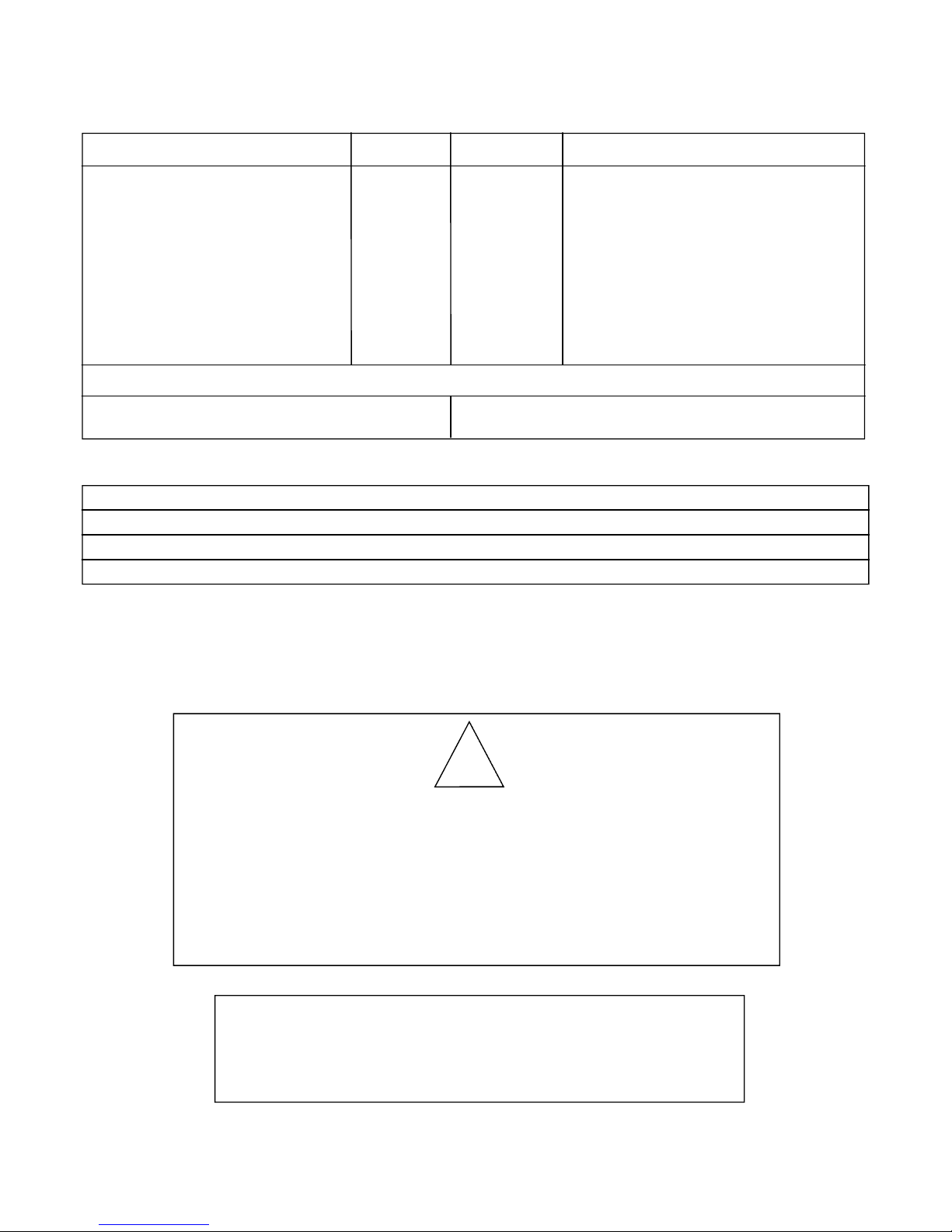
Aurora Climate Systems
A.B.N. 43 108 083 987
71 - 73 Overseas Drive
Noble Park VIC 3174
To be installed by an authorised person in
accordance with installation instructions
provided with appliance.
Model - Archer Manufactured by
Natural
IS900
44MjHr
0.75Kpa
0.46Kpa
2.55mm
2.40mm
AGA7978G
LPG
IS900
42.6MjHr
1.67Kpa
1.37Kpa
1.55mm
1.45mm
Gas Type
Model Type
Gas Consumption
Manifold Pressure Rear
Manifold Pressure Front
Injector Size - Front
- Rear
AGA Approval No
THE GUARD IS FITTED TO THIS APPLIANCE TO REDUCE THE
RISK OF FIRE OR INJURY FROM BURNS AND NO PART OF IT
SHOULD BE PERMANENTLY REMOVED
FOR PROTECTION OF YOUNG CHILDREN OR THE INFIRM, A
SECONDARY GUARD IS REQUIRED
Electrical conforms to AS3100 240V 50 Hz 97 Watts Max
Serial No:
Date of Manufacture:
IS900 IS900
5

INSTALLATION INSTRUCTIONS/ REQUIREMENTS
GENERAL SAFETY INSTALLATION REQUIREMENTS INFORMATION
1. This installation must conform with local codes or, in the absence of local codes, with AS/NZSG 5601.1
2. Provide adequate clearances around the product for servicing and ensure there are no obstructions to the combustion
air intake situated at the back of the heater. (Refer Page 5 and page 7)
3. The appliance must be installed level on a flat, solid continuous surface (i.e. wood, metal, concrete). Please
Note: Rough or uneven surfaces can cause operating failure, vibration or humming in the heater.
4. The Archer Gas Log Space Heater can be installed in a wide variety of ways and will fit nearly any room layout. It
may be installed in a recessed position, framed out into the room, or across a corner. For installation options refer
pages 14 through to 21.
5. This appliance (Insert and Freestanding Console Models) needs to be installed in such a way that the heater
can be removed at all times to service the heat exchanger, flue fan, over temp switch and thermistor which are
located in the rear section of the heater.
Note: Under no circumstances should the appliance be installed under conditions, which would not allow
for easy removal of the appliance to carry out routine inspection and service to the appliance, to do so will
void the warranty.
Note: On co axial single flue pipe (imitation zero clearance fireplace) a minimum of 25mm clearance must be
provided at the rear side and top of heater (Refer page 7)
Note: Where a mantel surround is being used on insert installations and imitation zero clearance fireplace
installations, the combustion air intake slot located in the top mantel surround must have no obstructions to allow
combustion air to enter through the slot to the combustion air inlet located at the back of the heater.
Note: Electrical connection/ insert models
In cases where the heater is directly wired into the 240 volt main power with the connection being behind the
heater not accessible to isolate the heater from main power an external isolation switch is required to allow
the heater to be disconnected from main power to allow for servicing of the heater.
6
THIS APPLIANCE SHOULD ONLY BE INSTALLED BY A QUALIFIED LICENSED GAS FITTER.
!
DUE TO HIGH TEMPERATURES, THE APPLIANCE SHOULD BE LOCATED OUT OF TRAFFIC AND
AWAY FROM FURNITURE AND DRAPERIES.
!
THIS APPLIANCE CAN ONLY BE FLUED IN ACCORDANCE WITH THE MANUFACTURER’S INSTRUCTIONS AS TESTED TO AGA CODE 601.
!
IN CASES WHERE THE INSTALLATION OF THE HEATER IS NOT IN ACCORDANCE WITH THE
MANUFACTURERS INSTRUCTIONS AND THE APPLIANCE CAN NOT BE REMOVED FOR SERVICING IN SUCH CASES WHERE SERVICE PERSONAL HAVE TO SPEND TIME TO REMOVE
THE HEATER OR CORRECT THE INSTALLATION A SERVICE CHARGE WILL BE APPLICABLE
TO THE CUSTOMER OF LABOUR AT $80 PER HOUR PLUS GST PLUS TRAVELING EXPENSES.
!
FAILURE TO INSTALL THIS APPLIANCE CORRECTLY IN LINE WITH THE MANUFACTURER
INSTALLATION REQUIREMENTS WILL CAUSE MALFUNCTION OF THE HEATER AND MAY
CAUSE A SERIOUS HOUSE FIRE.
!
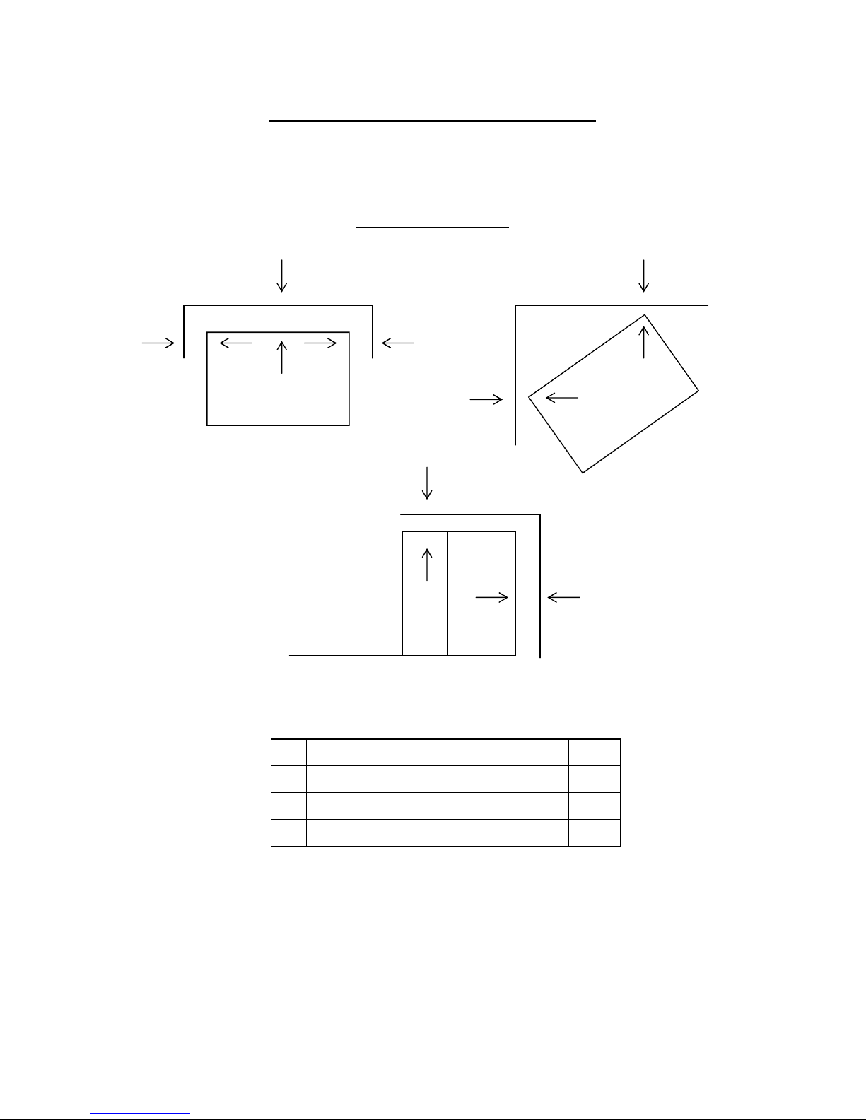
INSTALLATION INSTRUCTIONS
CLEARANCE TO COMBUSTIBLES
Insert Model IS900
A Rear Wall to Unit 25mm
B
Side Wall to Unit 25mm
C
Corner Installation 25mm
D Height Clearance From Unit 25mm
7
Note: The Archer Gas Log Space Heater has been tested and approved for zero
clearance to combustible materials. Aurora Climate Systems recommends that
clearances as listed above should be maintained to allow for removal of the
product for servicing and allow the heater on single flue pipe installations to
obtain sufficient combustion air.
B B
A
C
C
Zero clearance
No hearth required
A
D
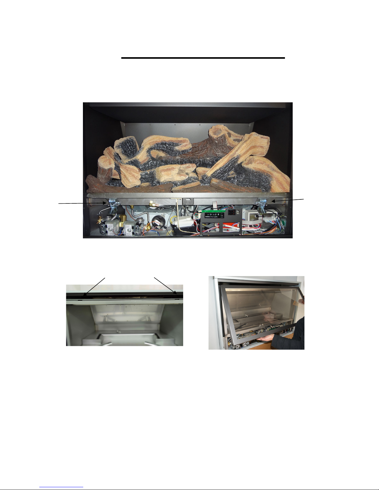
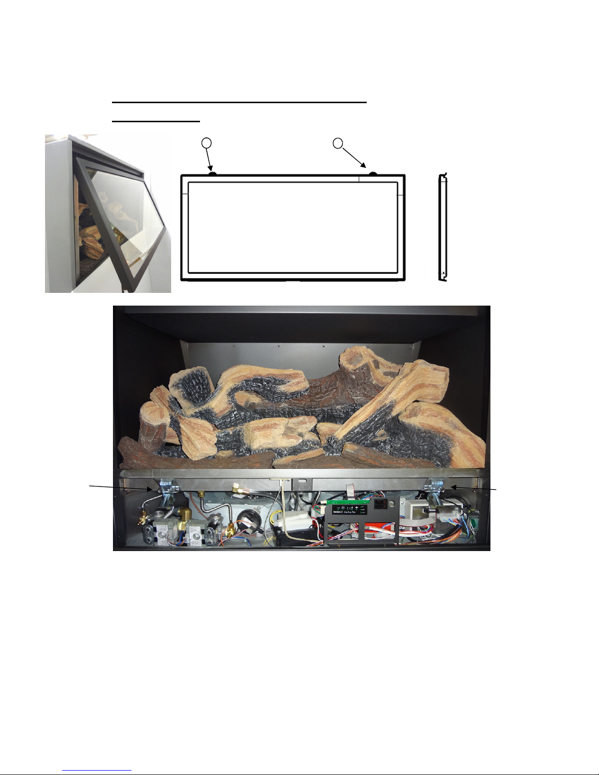
LOG INSTALLATION INSTRUCTIONS
1. Remove main front door by unlocking two door latches located at bottom of firebox see picture
below
2. Unhinge door from slots located at top of firebox by lifting door upwards see picture below
1. Carefully remove all cardboard protection from inside the firebox.
2. Note: All other logs in the firebox have been preset in the factory and their location should not
be changed. Check that logs have not moved or been damaged in transit. Check position of logs in
line with pictures on page 9-10
3. Inspect front and rear burner for particle or dust placement on top of burners. If any loose particles
or dust is visible on top of the front and rear burners remove particles .
4. After checking log placement and burners re fit main door to heater ensure door is correctly fitted
into hinges and attached securely. Reference page 11 fitting main door.
8
Door latch
Door latch
Slots for door hinge
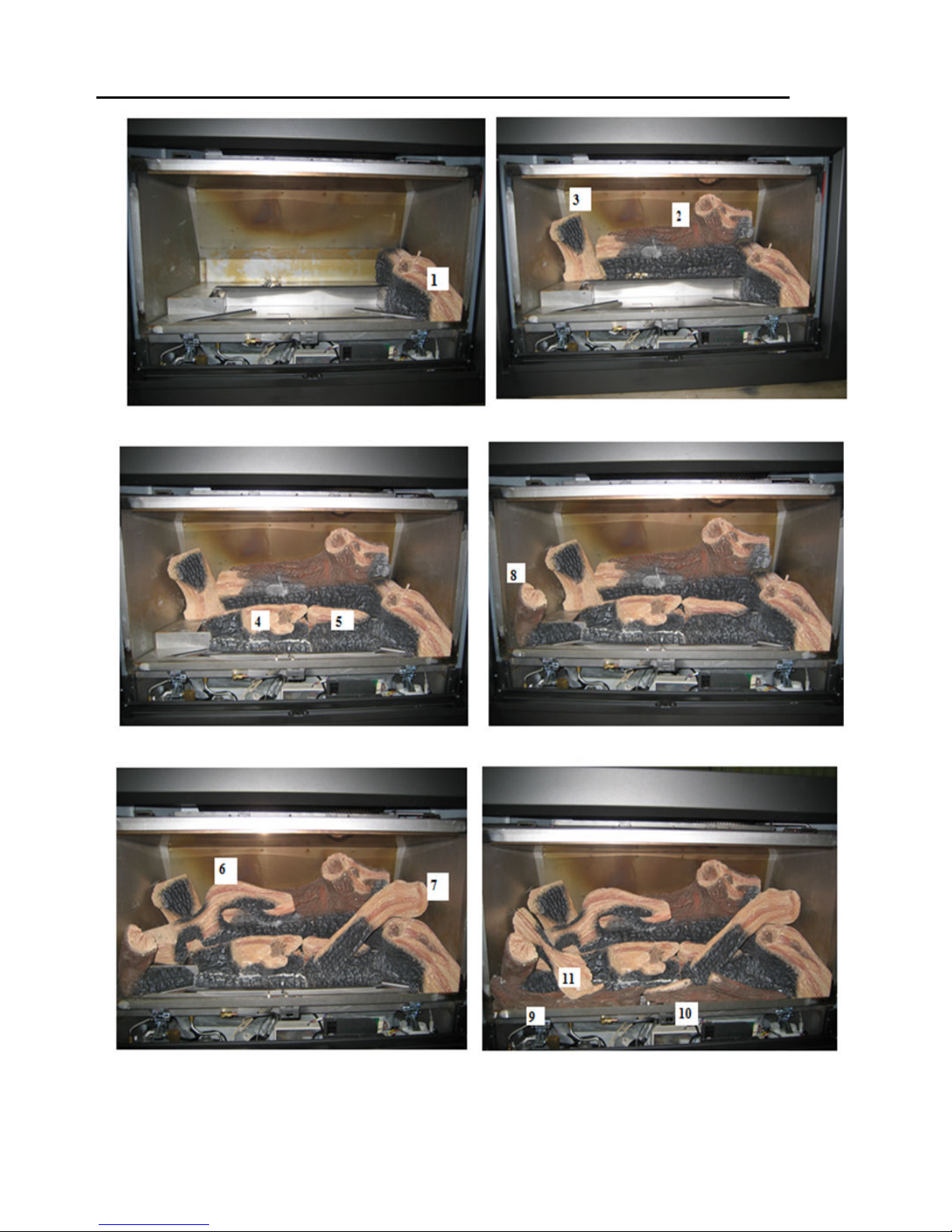
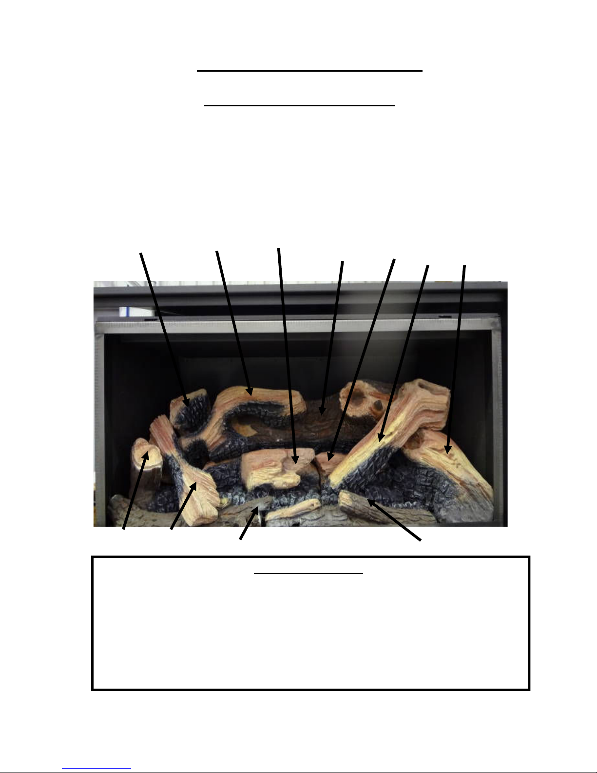
LOGS INSTALLATION INSTRUCTIONS (Refer to Page 12)
1. FIT No1 R/H LOG
2. No 2 REAR R/H LOG & No.3 REAR L/H REAR LOG
3. No4 MIDDLE L/H LOG & No5 MIDDLE R/H LOG
4. FIT No8 L/H CORNER LOG
5. FIT No6 L/H CROSS LOG & No R/H CROSS LOG
6. No9 FRONT LOG No 10 FRONT LOG & No11 L/H
FRONT CROSS LOG
9
10
Installers—Please Note
(A) LOG SETTINGS
Do not remove logs from heater unless absolutely necessary!! Logs have been present and aligned for correct performance * Only place cross logs in position as per instructions above.
Please note: Accurate placement of logs is critical for correct performance of heater. Please ensure the rear log is
hard up against the rear at the firebox at the base and at the top.
*Note: If logs have moved during transit only place logs in position as per instruction on pictures page.
1) Right Log 7) Right Top Log
2) Rear Right Log 8) Left Log
3) Rear Left Log 9) Left Front Log
4) Middle Left Log 10) Right Front Log
5) Middle Right Log 11) Left Top Log
6) Left Rear Top Log
3
6
4
2
5
7
1
8
11
9
10
INSTALLATION INSTRUCTIONS
LOG SET DIAGRAM—IS900
The Gas Log Kit contains the following:-
INSTALLATION INSTRUCTIONS
Door Fitting
1
1
Door Fitment: Fit main door by lifting door and fit two tabs on door (1) into the two slots on top of
louver (2) when fitting the two tabs into slots ensure that tabs on door frame protrude 2mm above
slots. Reference page 8 door removal.
After the two tabs on door frame have been located correctly into slots fold down door and engage
latches (3) into slots located at the bottom of door, secure door down by closing latches.
Note: Tabs on door frame need to be fitted correctly into slots on top of louver if not
fitted correctly door can not be folded down to engage latches for closing of door.
11
Door Latch
Door Latch

INSTALLATION INSTRUCTION
Surround
2. Fit surround by engaging 2 tabs (1)
into heat shield (2) top of firebox
picture 2.
Note: Bottom flap must be in open
position when fitting surround.
Surround Bottom
1
2
1
PICTURE 2
NOTE: INSTRUCTIONS CONTINUED ON NEXT PAGE
12
1. Remove 2 self tapping screws from LH/RH side panel. See picture 1.
PICTURE 1
Screws located here
Screws located here

INSTALLATION INSTRUCTION CONTINUED
Surround
4. After surround has been fitted top and bottom secure surround with 2 self tapping screws (provided) into
position Picture 3.
5. To close bottom flap bend the two legs on the flap slightly inwards to allow flap to be closed.
Once the two legs on the bottom flap have been bent slightly inwards to allow flap to be closed and once legs
on flap have cleared the firebox bend the two legs slightly outward so they lock in behind the firebox reference
Picture 3.
13
3. After locating and locking tabs into top heat shield slightly lift surround and locate surround on 2 tabs lo-
cated at the bottom of the L/H and R/H front side panel.
R/H Tab
L/H Tab

14
INSTALLATION INSTRUCTIONS
FLUING REQUIREMENTS
Co-Axial Flue Installations
Note: This appliance has only been approved for co-axial flue application if the flue (as
supplied by the manufacturer) is installed to an external wall or external fireplace.
(Refer installation diagram for Co-Axial Flue Installations Pages 16-20-21)
Single Flexi Installations
Note: This appliance has only been approved for single flue pipe installation if the unit and
flue pipe is installed in line with the manufacturer’s installation instructions.
(Refer installation diagram for single flue pipe installations Pages 15-17-18-19)
CONFIGURATION 1: Insert Models Pages 15-17-18-19 - Single Flexi Flue Application.
SINGLE PIPE 40mm ø 5.1 METRES HIGH INCLUDING 2 X 45°
ELBOW, 1 X 90° ELBOW, 1m FLEXIBLE PVC SECTION AND
ONE 75mm COWL.
CONFIGURATION 2: Insert Models for Installation on External Walls or External Fireplaces
Pages 16-20-21.
CO-AXIAL FLUE INTERNAL PIPE 40MM ø EXTERNAL PIPE
65MM ø BOTH PIPES IN PVC UP TO 1 METRE LENGTH FOR
WALL PENETRATION.
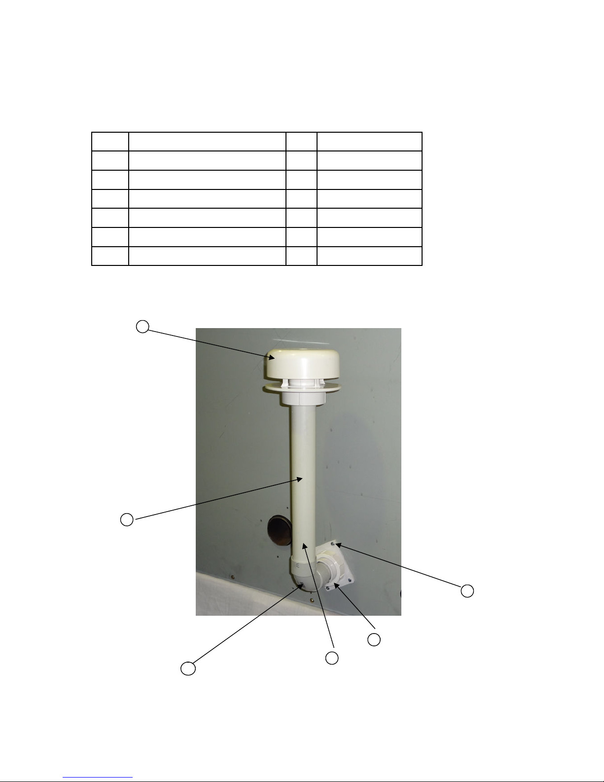
For applications on Flexible Single Flue refer pages 14-15-16-17-18
SINGLE FLUE KIT FOR ARCHER GAS LOG SPACE HEATER
No Description Qty
1 Single Flue Adaptor 1 Supplied with heater
2 40mm ø PVC Pipe 400mm long 1 Supplied with heater
3 90° PVC Bend 1 Supplied with heater
4 40mm ø PVC Pipe (up to 5.1m) Supplied by installer
5 Cowl 1 Supplied with heater
6 Self Tapping Screws 4 x ½" 4 Supplied with heater
2
1
6
5
15
4
3
 Loading...