

Page 1

i
Manual Number: 180101
USERS GUIDE
IPX Series
IPX-TC1-F ● IPX-TC1-C ● IPX-TC2-F ● IPX-TC2-C
IPX-TCW3-F ● IPX-TCW3-C
10G 4K IP Distribution
IPX-TCW3
IPX-TC1
IPX-TC2
Page 2

i
User Guide
SAFETY INSTRUCTIONS
Please review the following safety precautions. If this is the first time using this model, then read this manual
before installing or using the product. If the product is not functioning properly, please contact your local
dealer or Aurora for further instructions.
The lightning symbol in the triangle is used to alert you to the presence of dangerous voltage
inside the product that may be sufficient to constitute a risk of electric shock to anyone opening
the case. It is also used to indicate improper installation or handling of the product that could
damage the electrical system in the product or in other equipment attached to the product.
The exclamation point in the triangle is used to alert you to important operating and maintenance
instructions. Failure to follow these instructions could result in injury to you or damage to the
product.
Be careful with electricity:
Power outlet: To prevent electric shock, be sure the electrical plug used on the product power cord
matches the electrical outlet used to supply power to the Aurora product. Use only the power adapter
and power connection cables designed for this unit.
Power cord: Be sure the power cord is routed so that it will not be stepped on or pinched by heavy
items.
Lightning: For protection from lightning or when the product is left unattended for a long period,
disconnect it from the power source.
.
Also follow these precautions:
Ventilation: Do not block the ventilation slots if applicable on the product or place any heavy object on
top of it.
Blocking the air flow could cause damage. Arrange components so that air can flow freely. Ensure that
there is adequate ventilation if the product is placed in a stand or cabinet. Put the product in a properly
ventilated area, away from direct sunlight or any source of heat.
Overheating: Avoid stacking the Aurora product on top of a hot component such as a power amplifier.
Risk of Fire: Do not place unit on top of any easily combustible material, such as carpet or fabric.
Proper Connections: Be sure all cables and equipment are connected to the unit as described in this
manual.
Object Entry: To avoid electric shock, never stick anything in the slots on the case or remove the cover.
Water Exposure: To reduce the risk of fire or electric shock, do not expose to rain or moisture.
Cleaning: Do not use liquid or aerosol cleaners to clean this unit. Always unplug the power to the
device before cleaning.
ESD: Handle this unit with proper ESD care. Failure to do so can result in failure.
FCC
This device complies with Part 15 of the FCC Rules. Operation is subject to the following two conditions:
(1) This device may not cause harmful interference.
(2) This device must accept any interference received, including interference that may cause undesired
operation.
Trademarks
All trademarks in this document are the properties of their respective owners.
Page 3

ii
User Guide
TABLE OF CONTENTS
PACKAGE CONTENTS ............................................................................................................. 4
OPTIONAL ACCESSORIES ...................................................................................................... 5
INTRODUCTION ...................................................................................................................... 10
About ................................................................................................................................................... 10
Documentation .................................................................................................................................... 10
Features ............................................................................................................................................... 11
IPX-TC1-F, IPX-TC1-C, IPX-TC2-F, IPX-TC2-C Front ....................................................................... 12
IPX-TC1-F, IPX-TC1-C, IPX-TC2-F, IPX-TC2-C Rear ........................................................................ 14
IPX-TC1-F, IPX-TC1-C, IPX-TC2-F, IPX-TC2-C Bottom .................................................................... 15
IPX-TCW3-F & IPX-TCW3-C Front .................................................................................................... 16
IPX-TCW3-F & IPX-TCW3-C Rear ..................................................................................................... 18
UNDERSTANDING THE BASICS ............................................................................................ 19
Direct Connection with No Ethernet Switch ........................................................................................ 19
10GbE Ethernet Switch ...................................................................................................................... 19
1GbE Ethernet Port Usage ................................................................................................................. 19
Network Infrastructure ........................................................................................................................ 20
Isolated Network or Users Network .................................................................................................... 20
Controlling the IPX .............................................................................................................................. 20
Controlling the IPX with Multiple Servers for Redundancy ................................................................. 21
EDID and its Importance ..................................................................................................................... 21
Videowall Capabilities IPX-TC1/IPX-TCW3 ........................................................................................ 22
Videowall Capabilities IPX-TC2 .......................................................................................................... 22
HARDWARE INSTALLATION .................................................................................................. 23
Network Setup .................................................................................................................................... 23
Encoder Setup .................................................................................................................................... 23
Decoder Setup .................................................................................................................................... 23
QXP-2-IPX Control Server Setup ....................................................................................................... 24
Control Setup ...................................................................................................................................... 24
Web Setup Pages ................................................................................................................... 26
General Settings ................................................................................................................................. 26
Network Settings ................................................................................................................................. 27
Port Settings ....................................................................................................................................... 28
iPBT Settings ...................................................................................................................................... 29
USB Settings....................................................................................................................................... 30
Page 4

iii
User Guide
APPLICATIONS ....................................................................................................................... 31
Example 1: IPX-TCW3 Configured as Transmitter to IPX-TC1 Configured Receiver ........................ 31
Example 2: IPX Multi-Room ................................................................................................................ 32
Example 3: Matrix - Multiple IPX to Multiple IPX ................................................................................ 33
Example 4: Video-Wall ........................................................................................................................ 34
Example 5: KVM utilizing USB 2.0...................................................................................................... 35
SOFTWARE ............................................................................................................................. 36
CONNECTOR PIN DEFINITION ................................................................ .............................. 38
HDMI ................................................................................................................................................... 38
CAT5e/6/6A ......................................................................................................................................... 38
RS-232 ................................................................................................................................................ 39
IR (Infrared) ......................................................................................................................................... 40
APPENDIX 1 Troubleshooting ........................................................................................... 41
APPENDIX 2 Firmware Update .......................................................................................... 44
APPENDIX 3 Protocol ........................................................................................................ 44
APPENDIX 4 Recommended Cabling ............................................................................... 45
APPENDIX 5 Recommended Network Switches .............................................................. 46
5.1 Switch Speed ................................................................................................................................ 46
5.2 Packets Routing ............................................................................................................................ 46
5.3 Ethernet Switch Configuration ...................................................................................................... 47
5.4 Ethernet Switch Models ................................................................................................................ 48
APPENDIX 6 Technical Specifications .............................................................................. 49
APPENDIX 7 Warranty ....................................................................................................... 50
Page 5

4
User Guide
PACKAGE CONTENTS
Please make sure the following items are included within your package. Contact your dealer if any items
are missing or damaged.
Box Versions
IPX-TC1-F-MM
• 1 qty IPX-TC1-F Fiber Tranceiver Unit with Mult-mode SFP+ module
• 2 qty Mounting Ears and screws
IPX-TC1-C
• 1 qty IPX-TC1-C 10G RJ-45 Copper Tranceiver Unit
• 2 qty Mounting Ears and screws
IPX-TC2-F-MM
• 1 qty IPX-TC2-F Fiber Tranceiver Unit with Mult-mode SFP+ module
• 2 qty Mounting Ears and screws
IPX-TC2-C
• 1 qty IPX-TC2-C 10G RJ-45 Copper Tranceiver Unit
• 2 qty Mounting Ears and screws
Wall Plate 3 Gang Versions
IPX-TCW3-F-MM
• 1 qty IPX-TCW3-F Fiber Tranceiver Unit in white or black with Mult-mode SFP+ module
IPX-TCW3-C
• 1 qty IPX-TCW3-C 10G RJ-45 Copper Tranceiver Unit
Power supplies are sold separately.
Note: Go to www.auroramm.com for latest manual and firmware
Page 6

5
User Guide
OPTIONAL ACCESSORIES
• IPX-TC1-RK1 (1RU Rack mount holds 2 units)
Includes 4 Rails and 1 Blank
• IPX-TC1-RK5 (5RU Rack mount holds 12 units)
Includes 24 rails and 4 Blanks
• IPX-TC1-BLK (Blank Plate for Rack Mounts) & IPX-TC1-RAIL (For IPX-TC1 use in rack mounts)
• IPX-USB2 (USB 2.0 Extreme USB Option Card)
Page 7

6
User Guide
• IPX-DTE-1 (IPX-TC1 Dante/AES67 Option Card)
• IPX-DTE-2 (IPX-TC2 Dante/AES67 Option Card)
• QXP-2-IPX (IPX Embedded Linux Server Version)
Page 8

7
User Guide
• DXB-8/DXB-8i (8 Button Wall Plate)
• PS0081-1 (48V 24 Watt PoE Injector) Available in -US, -AU, - EU, and -UK worldwide models.
• PS0094-2 (48V 25 Watt Wall Supply) Available in -US, -AU, - EU, and -UK worldwide models.
• IR Receiver CA0026-1
• IR Emitter CA0061-1
• IR Blaster CA0049-1
Page 9
8
User Guide
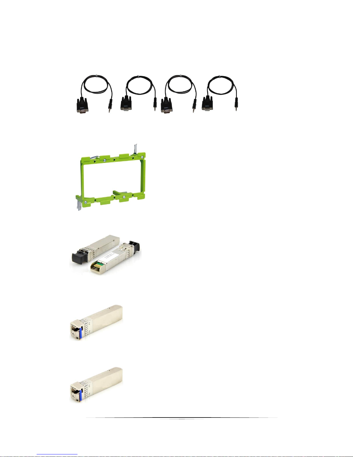
• RS-232 Adaptor (3.5mm TRS to FEMALE DB9 2-TX 3-RX) CA0052-F2T3R
• RS-232 Adaptor (3.5mm TRS to FEMALE DB9 3-TX 2-RX) CA0052-F3T2R
• RS-232 Adaptor (3.5mm TRS to MALE DB9 2-TX 3-RX) CA0052-M2T3R
• RS-232 Adaptor (3.5mm TRS to MALE DB9 3-TX 2-RX) CA0052-M3T2R
• LVR-3G 3 Gang Electrical Ring
• IPX-SFP-10GMM-1 10G SFP+ Multi-mode LC 50/125 Module
• IPX-SFP-10G32C1 10G SFP+ BIDI Single Mode 1330/1270nm Module 10KM
• IPX-SFP-10G23C1 10G SFP+ BIDI Single Mode 1270/1330nm Module 10KM
Page 10

9
User Guide
• IPX-SFP-10G20 10G SFP+ Single Mode Dual Module 1310nm 20KM
• IPX-SFP-PPC-1 SFP+ 10G Passive Patch Cable 1M (3ft)
• IPX-SFP-OM3DXLC-1 OM3 Fiber 50/125 Multi-mode LC Patch Cable 1M
Page 11

10
User Guide
INTRODUCTION
About
The IPX Series provides one of the most advanced IP Streaming solutions on the market utilizing Aurora’s
IPBaseT™ technology, which synergizes various IP/AV standards to work together as one. It is the
industry’s first 4K2K transceiver with zero compression and latency based on BlueRiver NT™/NT+ platform.
Using a transmitter (encoder) and receiver (decoder), respectively, used to be the standard – until now.
The IPX can be set up as either one to make installation, inventory, and troubleshooting easier.
Another industry first is the option slot to add other IP capabilities, like ExtremeUSB® (USB 2.0 over IP) or
Dante® audio, for a more complete, distributed system.
Audio, video, data, and control can be sent securely to one or many units using off-the-shelf 10G Ethernet
switches. When the IPX is set up to be a transmitter, the 2 HDMI inputs become a source switch and the
HDMI output becomes a potential loop out. When set up as a receiver, a user can select the local HDMI
inputs or an IP source. Seamless switching of the sources further enhances the presentation. Regardless
of how the IPX is set up, the audio can be de-embedded at any location, break away, and/or be sent to or
received from a Dante® enabled device. The USB 2.0 option is also flexible, working as a KVM and/or a
high-speed data transfer (480Mbps) for memory sticks. Each IPX USB feature can also be set as a host or
a device. To keep the system friendly, a customizable OSD and web server are available to be programmed
as required. For RJ-45 LAN devices, the 1G Ethernet port allows full bandwidth end-to-end over the IPX
10G fiber or copper port.
Choice is important. That’s why the IPX fiber version has an SFP+ port that can use single or multi-mode
fiber – making the IPX Series the ultimate AV IP product on the market today.
Documentation
Aurora provides many documents to support the IPX series and accessories. Below is a list of the
available documents that can be found on the download tab of the IPX products or the customer portal.
• IPX Series Network Switch Recommendation & Configuration
• QXP-2-IPX User Guide
• IPBaseT Manager Users Guide
• IPX Series Protocol Guide (Available only on Customer Portal)
• IPBaseT FAQ (Frequently Asked Questions)
• IPBaseT IPX Series AV Evolution for an Industry Revolution (Features and the benefits over
tradition Matrix)
• IPBaseT Brochure
Page 12

11
User Guide
Features
Configure as Transmitter (Encoder) or Receiver (Decoder)
4K60 4:4:4 (IPX-TC2), 4K60 4:2:0 (IPX-TC1) Over 10G Fiber or Copper
Zero Compression & Zero Frame Latency (22us) for 4K60 4:2:0 and below
3:1 Lossless Compression & Zero Frame Latency (100us) for 4K60 4:4:4
Secure Content Encryption
128x128 Capable with HDCP, Larger for Non-Encrypted Sources
Videowall Capability with Zero Latency*
Windowing/Multi-viewer up to 32 windows (IPX-TC2)
3ms Scaling (IPX-TC2)
Seamless & Break-away Switching
SFP+ for Multi/Single Mode Fiber
10/100/1000Mbps LAN
2 HDMI Inputs, 1 HDMI Output
Line In/Out Stereo
RS-232 Serial Port & IR (Bidirectional)
Integrated Web Server for Custom Control Pages
ExtremeUSB® - USB 2.0 480Mbps Option (Host or Device Configurable)
Dante®/AES67 IP Audio Option
Front Keypad & IR Remote Option
Auto Sense Switching
Rack & Under Table Mounting (IPX-TC1/TC2)
3 Gang Wall Plate Mounting in white or black (IPX-TCW3)**
* Videowall has certain limitations for IPX-TC1. Please refer to the videowall section of this manual
for further details.
** Wall plate versions require full 3 gang electrical box space. Some electrical boxes and mud rings
do not accommodate the full size. IPX-TCW3 wall box dimensions are 5.54” x 2.83” x 1.404”. Wall box
portion depth is 1.404” without option card and 2.25" with option card.
Page 13
12
User Guide
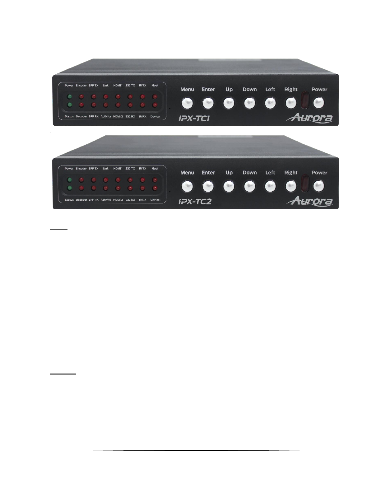
IPX-TC1-F, IPX-TC1-C, IPX-TC2-F, IPX-TC2-C Front
LEDs
• Power/Status – Power will light green when unit is on or in standby. Status will blink at a
normal pace during regular operation and slower pace when in standby.
• Encoder/Decoder – Encoder (transmit) or Decoder (receiver) will be lit when set
accordingly.
• SFP TX/RX – Will blink when data is being transmitted or received for fiber or copper
versions.
• Link/Activity – For the 10G fiber or copper connection.
• HDMI 1/HDMI 2 – Will light accordingly based on input selection. If both are lit, then it is
the remote stream when set as a decoder. If neither is lit, then no source is routed.
• 232 TX/RX – Will blink when RS-232 data is being sent or received.
• IR TX/RX – Will blink when IR signal is being sent or received
• Host/Device – For USB option. Host will be lit if set for PC to be connected to the USB.
Device will be lit if set for peripherals like keyboard or mouse is to be connected.
Buttons
• Power Button – Press and hold for 5 seconds for power standby.
• Left/Right Button – Press and hold for 10 seconds for restore to factory default.
• Menu Button – Press and hold for 5 seconds switch between encode and decode mode.
• Up Button - Select next input source.
• Down Button - Select previous input.
• Up/Down Button – Press and hold for 5 seconds to output IP info at 9600 baud rate on
RS-232 port.
Page 14

13
User Guide
Miscellaneous
• IR Window – Future use for IR remote.
Special Functions
• Streaming Factory Default – Press & hold Down and Right together for 10 Seconds. This
will only restore default for the mode the unit is currently set to.
• Web Server Factory Default – Press & hold Left and Right together for 10 Seconds.
• EDID Transfer - Press and hold Right button for 10 seconds on decoder device only.
Note: Default Settings - 9600 baud rate; default IP 192.168.1.100; autosense off.
Page 15

14
User Guide
IPX-TC1-F, IPX-TC1-C, IPX-TC2-F, IPX-TC2-C Rear
Rear
• 48VDC – 48 Volt isolated power input.
• SFP+ – Multi-mode or single mode SFP+ 10G modules for the IPBaseT connectivity.
• 10G – RJ-45 10G network connection for the IPBaseT connectivity. Unit can be powered
with 10G PoE or PoH injector.
• HDMI In 1/2 – HDMI inputs. (IPX-TC1: HDMI 1.4, IPX-TC2: HDMI 2.0)
• HDMI Out – HDMI Output to Display. (IPX-TC1: HDMI 1.4, IPX-TC2: HDMI 2.0)
• RS-232 – Serial port pass-through and control up to 115Kbps.
• IR – Bi-directional IR input/output 30kHz-60kHz. Emitter must be mono 3.5mm TS and
Photo Receiver must be stereo 3.5mm TRS. Note: It is important to use 5V only photo
receiver which is with carrier and inverted.
• Audio In – Stereo audio input.
• Audio Out – Audio de-embedded output.
• Ethernet – 10/100/1000Mbps LAN. Can power the unit with PoE+ from injector or switch.
• USB – 480Mbps USB 2.0 Type A to be connected to a host (PC) or device (ex. Mouse,
keyboard, etc). Extreme USB SO-DIMM option card (IPX-USB2) must be installed for
USB to function.
Page 16

15
User Guide
IPX-TC1-F, IPX-TC1-C, IPX-TC2-F, IPX-TC2-C Bottom
Bottom
• SO-DIMM Option Card Slot for USB 2.0 and Dante options.
Note: The MAC address for the Dante or USB option will be on the card label.
Page 17
16
User Guide
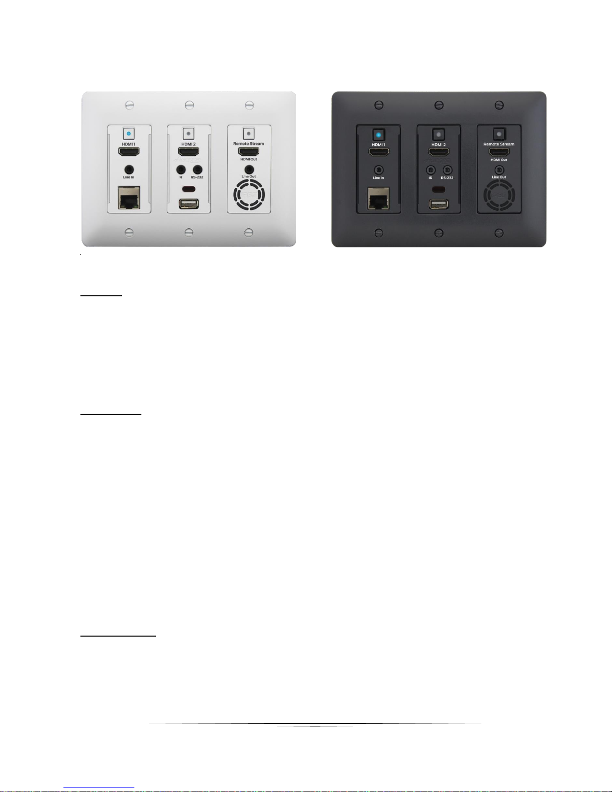
IPX-TCW3-F & IPX-TCW3-C Front
Buttons
• HDMI 1 – Selects HDMI Input 1 (Lights Red, Green, or Blue).
• HDMI 2 – Selects HDMI Input 2 (Lights Red, Green, or Blue).
• Remote Stream – Selects remote stream assigned when set as decoder (Lights Red,
Green, or Blue). If held for 5 sec will switch between encode and decode modes. Stream
button will light blue when in encode mode.
Connectors
• HDMI In 1/2 – HDMI inputs up to 4K UHD 30Hz.
• HDMI Out – HDMI Output to Display.
• RS-232 – Serial port pass-through and control up to 115Kbps.
• IR – Bi-directional IR input/output 30kHz-60kHz.
• Audio In – Stereo audio input.
• Audio Out – Audio de-embedded output.
• Ethernet – 10/100/1000Mbps LAN.
• USB – 480Mbps USB 2.0 Type A to be connected to a host (PC) or device (ex. Mouse,
keyboard, etc). Extreme USB SO-DIMM option card (IPX-USB2) must be installed for
USB to function.
• Vent Holes – Temperature controlled low noise fan. Designed for easy cleaning and
replacement if ever necessary.
Miscellaneous
• IR Window – Future use for IR remote.
Page 18

17
User Guide
Special Functions
• Streaming Factory Default – Press & hold HDMI 1 for 5 seconds. This will only restore
default for the mode the unit is currently set to.
• Web Server Factory Default – Press & hold HDMI 2 for 5 seconds.
• EDID Transfer - Press and hold HDMI 1 and HDMI 2 for 5 seconds on decoder device
only.
Note: Default Settings - 9600 baud rate; default IP 192.168.1.100; autosense off.
Page 19
18
User Guide
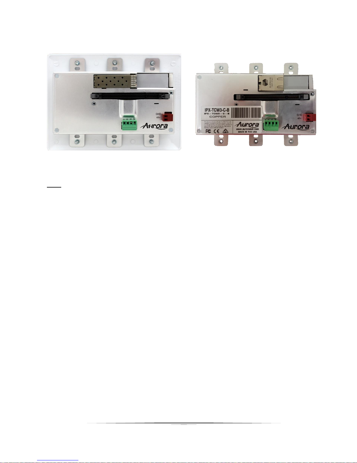
IPX-TCW3-F & IPX-TCW3-C Rear
Rear
• 48VDC – 48 Volt isolated power input.
• SFP+ – For multi-mode or single mode SFP+ 10G modules (IPX-TCW3-F) for the
IPBaseT zero compression/latency connectivity.
• 10G – RJ-45 10G network connections (IPX-TCW3-C) for the IPBaseT zero
compression/latency connectivity. Unit can be powered with 10G PoE or PoH injector.
• RS-232 – Serial port pass-through and control up to 115Kbps. Also, has 5V for
connection to DXB-8 8 button wall controller.
• SODIMM Expansion Slot for USB and Dante options. Cover supplied for card protection.
Note: Copper RJ-45 is tab down. Do not use a boot over the connector or it will be too
snug. To release the cable a flat head screw driver should be used from the side to lift
tab from underneath.
Wall plate versions require full 3 gang electrical box space. Some electrical boxes and
mud rings do not accommodate the full size. IPX-TCW3 wall box dimensions are 5.54” x
2.83” x 1.404”. Wall box portion depth is 1.404” without option card and 2.25" with
option card.
Page 20

19
User Guide
UNDERSTANDING THE BASICS
Direct Connection with No Ethernet Switch
The IPX Series is designed to automatically tunnel the video, audio, USB, RS-232, and IR if they are
connected without an Ethernet switch or connected server (QXP-2-IPX).
10GbE Ethernet Switch
It is important to use a non-blocking IGMP 10GbE switch with IGMP snooping. The size of the switch is
based on the requirements of the project. With this in mind, consider if extra port capacity is required for
future expansion. If you run out of port capacity, you can always add another 10GbE switch in the future.
The IPX, when set to encoder (TX), determines the bandwidth that will be multicast across the network.
24bit 4k@30Hz will use about 6Gbps and 3Gbps for 24bit 1080p@60Hz (Data Rate in bits per second =
Color Depth x Horizontal Resolution x Vertical Resolution x Frame Rate). This does not include the 1G
LAN, 480Mbps, RS-232, IR over the same transmission if required. If 10 units are set as encoders, and
4K@30Hz is the desired video resolution, then 64Gbps of bandwidth will be required if uplinked to
another switch. If the available bandwidth between the two 10GbE switches is less than 64Gbps, then
packets will drop and information will be lost. It is also a good idea to take into account overhead and
assume 15% bandwidth loss to play it safe. Since each port is bi-directional 10Gbps, it enables any port
to be used as an encoder or decoder. The AV industry is used to standard distribution topology limitations
of 4x4, 8x8, 16x16, etc. With networked based video distribution, a 48 port 10GbE switch as an example
can be 24x24, 1x47, 47x1, 12x36, etc.
1GbE Ethernet Port Usage
The 1GbE LAN port on each IPX unit is a full bandwidth independent port that is part of the 10GbE
switch. For every IPX unit added to the 10GbE network, it is the same as adding another 1GbE LAN port
to a switch. Every IPX 1GbE LAN port is part of a 1GbE switch, relative to the number of IPX units on the
network. This allows for using the IPX in place of a secondary 1GbE Ethernet infrastructure to each
location and even using it as a low bandwidth video streaming, within the high bandwidth streaming. It is
important to not connect more than one IPX unit into the same 1GbE network or there will be
communication issues. If more than one IPX unit is connected into the same 1GbE network, it would be
the same as taking 2 Ethernet switches and connecting multiple ports to each other, as action that will
totally disrupt the network (it will cause a broadcast/network storm). Connecting computers or other LAN
peripherals throughout the IPX 1GbE LAN ports will work the same as any other Ethernet switch typically
used. A more advanced usage would be to use the IPX 1GbE LAN port to have a local H.264 encoder
send lower bandwidth content over the IPX 10GbE infrastructure. This way local AV content is sent real
time uncompressed using the 10GbE IPX infrastructure and then for distant learning, computer viewing,
Page 21

20
User Guide
or internet usage the H.264/H.265 compressed stream using the same 10GbE infrastructure to other low
bandwidth destinations.
Network Infrastructure
The raw network cabling as well as the patch cables are as important as the switch. For 10GbE networks
fiber cable is preferred. If using copper, unshielded cable is preferred for optimal performance and is
important to follow the standard rules for running Ethernet cables. No sharp bends, coiling, putting near
power lines, grouping tightly together with other LAN cables, etc. The grade of the copper cable is
important too as it will determine the distance. CAT6A will reach 100m, CAT6 55m, and CAT5e 40m.
Fiber can achieve substantially greater lengths and does not have the issues of copper with running
together, power line interference, etc. OM3 multi-mode fiber (MMF) will go almost 1000ft/300m. Singlemode fiber (SMF) can go tens of miles if required.
Isolated Network or Users Network
When discussing a networked based video solution, many times it is assumed it has to be on the client’s
network. This is not true. The application determines the type of network to be used. For example, if it is
simply being used as a typical AV matrix switch with no distribution throughout the facility, then a 10GbE
switch can be used just for that room. Just because it is Ethernet based does not mean it has to be used
on the main network. The Ethernet switch is simply used as the end point for all the cables and the glue
that holds everything together. In other words, it takes the place of the standard AV matrix switch
topology. If only remote control is required from the main network, then connect the 10GbE switch to the
main network and allow the control data between the 10GbE switch VLAN and the main network. Even if
the VLAN is part of the main network it does not mean you will use all the bandwidth. The purpose of
IGMP, is to only send the multicast data to the ports specified, which would be where the IPX units are
connected to. Non-blocking switch assures full bandwidth is available for all ports as required.
Controlling the IPX
To simplify control of the IPX, QXP-2-IPX is available, an embedded Linux server, which mitigates all
communications to all the IPX units (devices and wall plates). The QXP-2-IPX can be controlled via
Telnet with Aurora’s IPBaseT Manager, a Microsoft Windows® software. It can also be controlled from
other Aurora control products or 3rd party control systems with the available API. In order to obtain the
IPX Server API commands you must be dealer status otherwise an NDA is required and is at the
discretion of Aurora.
Page 22

21
User Guide
Controlling the IPX with Multiple Servers for Redundancy
Multiple QXP-2-IPX servers can run on the same network for redundancy. It is important only one
communicates at any given time or incomplete commands may occur between units communicating
simultaneously. IPBaseT Manager will only connect to one server at a time but it is important for every
PC running IPBaseT Manager they all point to the same server at the same time. If a server losses
communication, then all clients should reconnect to the same backup server.
When using 3rd party control systems, this can be done automatically. Have the control system send a
query to the QXP-2-IPX to receive a response through the telnet connection. If no response is received
have the 3rd party control device target the backup server until the main server starts to communicate
again. Do not use ping for this operation as it only confirms a network connection but does not confirm
actual IPX API Server operation. Pinging will be effective for diagnostics to determine if the network
connection to the server is lost or if there are significant delays in the network.
EDID and its Importance
One of the most forgotten setup procedures in AV systems is the EDID. The EDID comes from the
destination (display, VTC, recorder, etc.) and must be saved into the encoder and decoder HDMI input
ports. This allows the source (Blu-ray, computers, etc.) to know the capabilities of the destination. This
includes the audio type if any, video resolution and timing, color space, color depth, and more. If no EDID
is present an HDMI device will revert to lowest resolution in DVI mode which also means no audio. If the
wrong EDID is used, the image may look pink, green, or have no image at all. To make matters more
complex, if different destinations/displays are in use in a matrix configuration, then it is important to use
an EDID with a common denominator or only one or the other destination may work. In an ideal
installation all the destinations should have the same capabilities for optimal performance. I this is not
possible a scaler may have to be implemented to assist in the compatibility.
For example, there are 2 displays one 1080p the other 4k UHD. If the EDID of the 4K display is used, the
1080p will not see an image if the source is capable of 4K. If the 1080p EDID is used, then both will see
the image but the 4K will never benefit from 4K content. In a situation where this is unacceptable, a 4K
scaler can be used on the 1080p screen to down scale the 4K content so the 4K EDID can be used and
the better screen can have a benefit. Note scalers do add frame latency and can affect image quality
based on the quality of the scaler. This is why it is always ideal to use destinations with similar
capabilities for optimal performance.
Audio can be impacted just as easily. If a destination is 6-channel surround sound capable and the other
destination is not, then the EDID from the 5.1 destination cannot be used, or there will be no audio on the
other destination. In most commercial installations it should not be an issue to choose the lowest common
Page 23

22
User Guide
denominator, which is 2-channel audio, but in cases where you must have surround sound then a downmixer for the 2-channel destination must be used.
In some cases, a custom EDID could be created, as the audio and video are mismatched between the
destinations. This can occur for example, when one destination has 4K 2-channel audio and the other
1080p with multichannel surround sound. If the EDID of the 1080p destination is used, audio will not be
present on the 4K destination. If the 4K EDID is used, there will be no video present on the 1080p
destination. The only way to solve this issue, is a new EDID combining the common features. In this case
an EDID which is set at 1080p with 2-channel audio is the solution.
Videowall Capabilities IPX-TC1/IPX-TCW3
The IPX-TC1 & IPX-TCW3 videowall mode has the ability to take in a 4K UHD signal and create a low
latency high quality videowall. It is important to note it does this without the use of the scaler as it relies
on the scaler and capabilities of the display. The way the mode works is by dividing the input resolution
by the amount of displays. For example, a 2x2 videowall will become four 1080p signals from a 4K UHD
signal. It is highly recommended before selecting the IPX as a videowall controller to test it with the
display model to be used to make certain the scaler capabilities of the display have a wide enough range
to handle the resolution variances that may be sent. In the case of a 4x4 (max configuration) a 4K UHD
input will be divided by 4 making a resolution of 960 x 540. Some displays may not accept that resolution.
The IPX also has bezel compensation and some displays do not fare well with the changes to the signal
when using this feature. While we would love to make a list of compatible displays unfortunately there are
too many to test with and it is best advised if using this feature to request a demo to test with your specific
display.
Videowall Capabilities IPX-TC2
The IPX-TC2 videowall mode has the ability to take in a 4K60 UHD signal and create a low latency high
quality videowall. With its internal low latency scaler, videowalls can be created up to 8x8 for basic
videowall configuration and 16x16 with additional bridging technique.
Page 24

23
User Guide
HARDWARE INSTALLATION
Network Setup
1. Connect a 10GbE network switch and make certain IGMP Snooping features are enabled.
2. Connect fiber or UTP CAT cable accordingly to the network switch and to the IPX units.
3. Connect a QXP-2-IPX Server to the network switch and power on. Follow instructions for the QXP-
2-IPX to set the IP address for remote control.
Encoder Setup
1. Plug HDMI source(s) into the inputs. Local display should be connected to the HDMI output.
Connect any other RS-232, IR, or audio accordingly. If USB is to be connected, make certain the
IPX-USB2 option is installed.
2. Connect power via 48v red euro connector, PoE of 10G if copper version, or PoE of 1G Ethernet
port (box version only). If using 10G PoE make certain it is a 10G PoE or PoH injector. Unit will
take about 20-30 seconds to initialize.
3. Make certain the unit’s LED is set to Encode. If not, for box version use the front menu button by
holding for 5 seconds or the stream button on the wall plate version. Encoder/decoder mode can
also be changed with the internal web server or IPBaseT Manager.
4. For the box version select the input to be streamed using the front up or down buttons to choose
HDMI 1 or 2. The HDMI 1/2 LED will light accordingly. For the wall plate use the labeled buttons
accordingly. This can also be down with the web server or IPBaseT Manager.
5. Every IPX unit has 2 MAC and 2 IP addresses. One is for the IPBaseT video engine. The other is
for the internal web server. The internal web server has a default IP address of 192.168.1.100 and
must be changed or it will conflict with other units. It can be changed using IPBaseT Manager or
through the built in setup pages at 192.168.1.100. If using the web server to change the IP settings
of the IPX unit, you must isolate the unit from a production network (i.e. do not connect the IPX
unit on a production network, until you have changed its IP address to suit your network). We
highly recommend you change the IP address of all the IPX units by connecting them one
after the other to a local PC system using the 1GbE port. Future versions of IPBaseT
Manager will allow the changing of web server IP address and functionality without having
to isolate making setup faster and easier. Then you can safely deploy them on the production
network.
Decoder Setup
1. Plug the display into the HDMI output. If local sources will also be connected to the decoder, use
the HDMI inputs 1 and/or 2. Connect any RS-232, IR, or audio accordingly. If USB is to be
Page 25

24
User Guide
connected, make certain the IPX-USB2 option is installed.
2. Connect power via either 48VDC red euro connector port or the 1GbE PoE port of the IPX unit. If
using IPX-TC1-C and want to power the unit through the 10GbE PoE port, make certain it is a
10GbE PoE or PoH injector. Unit will take about 20-30 seconds to initialize.
3. Make certain the unit’s LED is set to Decode. If not, for device version, use the front menu button
by holding for 5 seconds or the stream button on the wall plate version. Encoder/Decoder can
also be changed with the internal web server or IPBaseT Manager.
4. For the box version select the input to be streamed using the front up or down buttons to choose
HDMI 1, 2, or stream. The HDMI 1/2 LED will light accordingly. If both are lit, then stream is
selected. For the wall plate use the labeled buttons accordingly. This can also be down with the
web server or IPBaseT Manager.
5. Every IPX unit has 2 MAC and 2 IP addresses. One is for the IPBaseT video engine. The other is
for the internal web server. The internal web server has a default IP address of 192.168.1.100 and
must be changed or it will conflict with other units. It can be changed using IPBaseT Manager or
through the built in setup pages at 192.168.1.100. If using the web server to change the IP settings
of the IPX unit, you must isolate the unit from a production network (i.e. do not connect the IPX
unit on a production network, until you have changed its IP address to suit your network). We
highly recommend you change the IP address of all the IPX units by connecting them one
after the other to a local PC system using the 1GbE port. Future versions of IPBaseT
Manager will allow the changing of web server IP address and functionality without having
to isolate making setup faster and easier. Then you can safely deploy them on the production
network.
QXP-2-IPX Control Server Setup
1. Connect the QXP-2-IPX USB to a USB Hub for keyboard and mouse use. Plug the HDMI into a
monitor capable of 720p or higher.
2. Connect the LAN to a PoE switch or PoE injector with LAN connection.
3. Unit will boot in about 45 seconds.
4. In the lower right, use the mouse to right click on the network settings.
5. Under the IPV4 tab add a fixed IP unless you are using the MAC address from the switch to
control the IP Address through DHCP. It is highly recommended to have an IP Address that won’t
change. If a static IP is added, delete the Auto or boot time will be very long as it searches.
Control Setup
1. Launch IPBaseT Manager and connect to the QXP-2-IPX Server IP Address. The units on the
network will populate into the encoder and decoder fields accordingly. You will then be able to
Page 26

25
User Guide
change settings, save EDID, route, and more. If a control system is to be used, make certain it is
connected to the same network and follows the Aurora IPX API protocol.
Important:
• Take note of the MAC Address of every unit. It can be found on the underside or rear of
the unit. The MAC Address is how you will identify the unit relative to its location.
• Make certain all units are using the latest firmware.
• Remember to setup EDID for proper operation.
Page 27
26
User Guide
Web Setup Pages
Web Setup pages can be accessed by typing in the IP address of the unit followed by /setup (example:
192.168.100.1/setup). You will then be prompted for a password. Default password is admin. Make
certain if all the IPX units are already connected to the 10GbE network that each IPX web server has a
unique IP Address or there will be communication issues. Note the Web pages for the IPX-TC1 and IPX-
TC2 are the same.
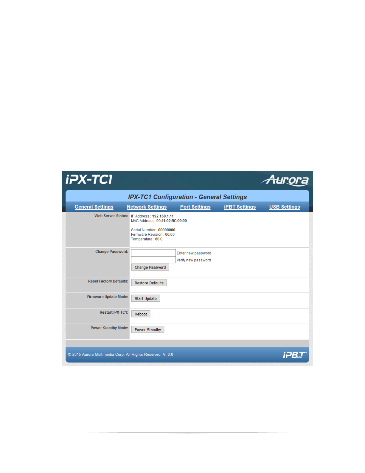
General Settings
The General Settings is for the web server part of the IPX unit. The IP address, MAC address, and
firmware revision are for the web server.
Page 28
27
User Guide
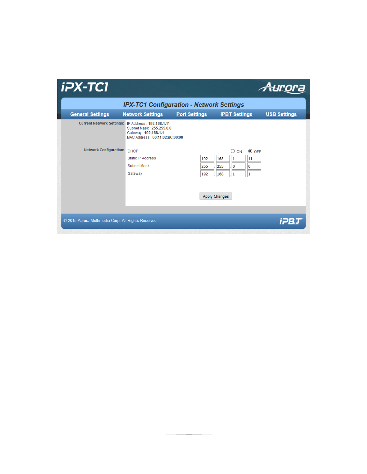
Network Settings
The Network Settings page is to configure the web server IP settings.
Page 29
28
User Guide
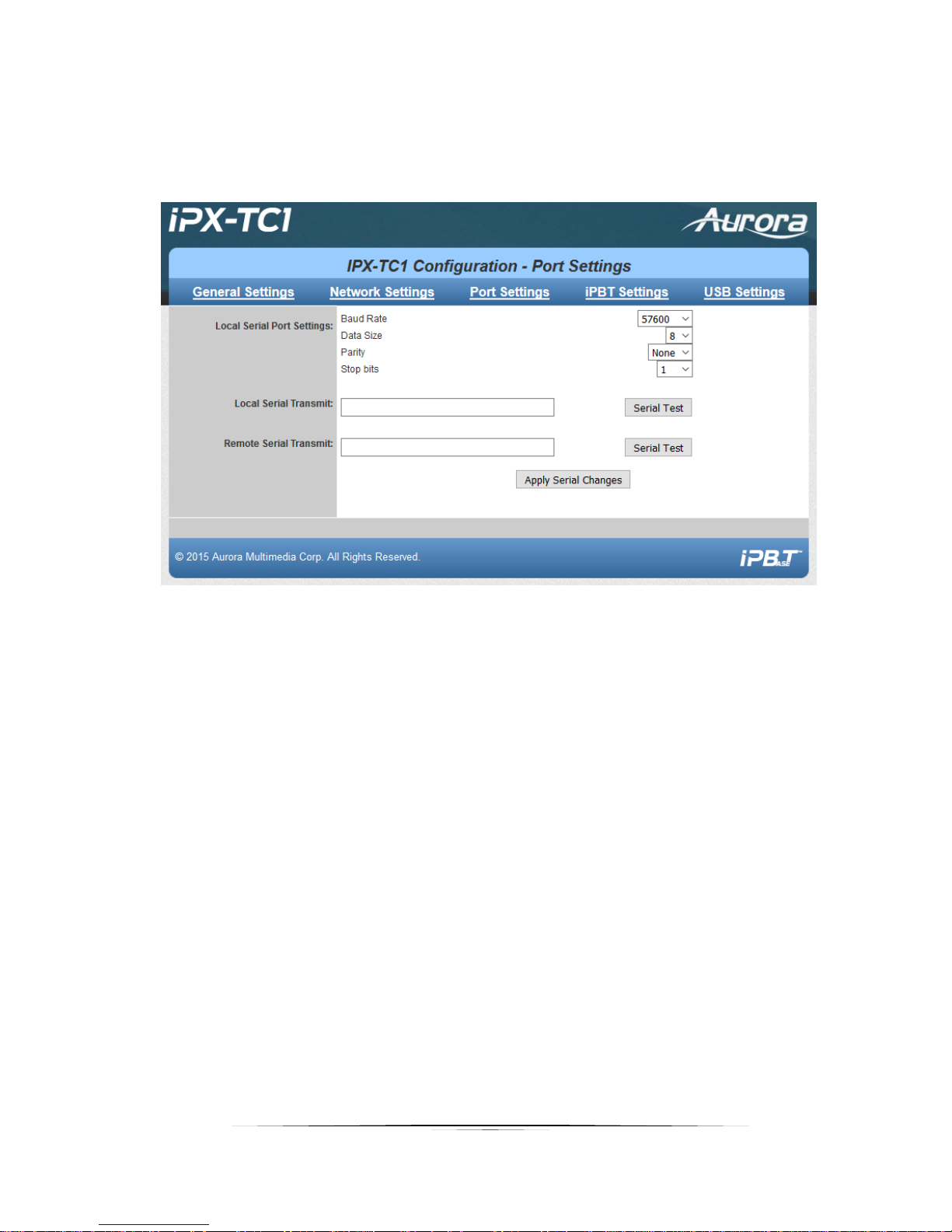
Port Settings
Port Settings allow setup of the RS-232 and IR ports.
Page 30
29
User Guide
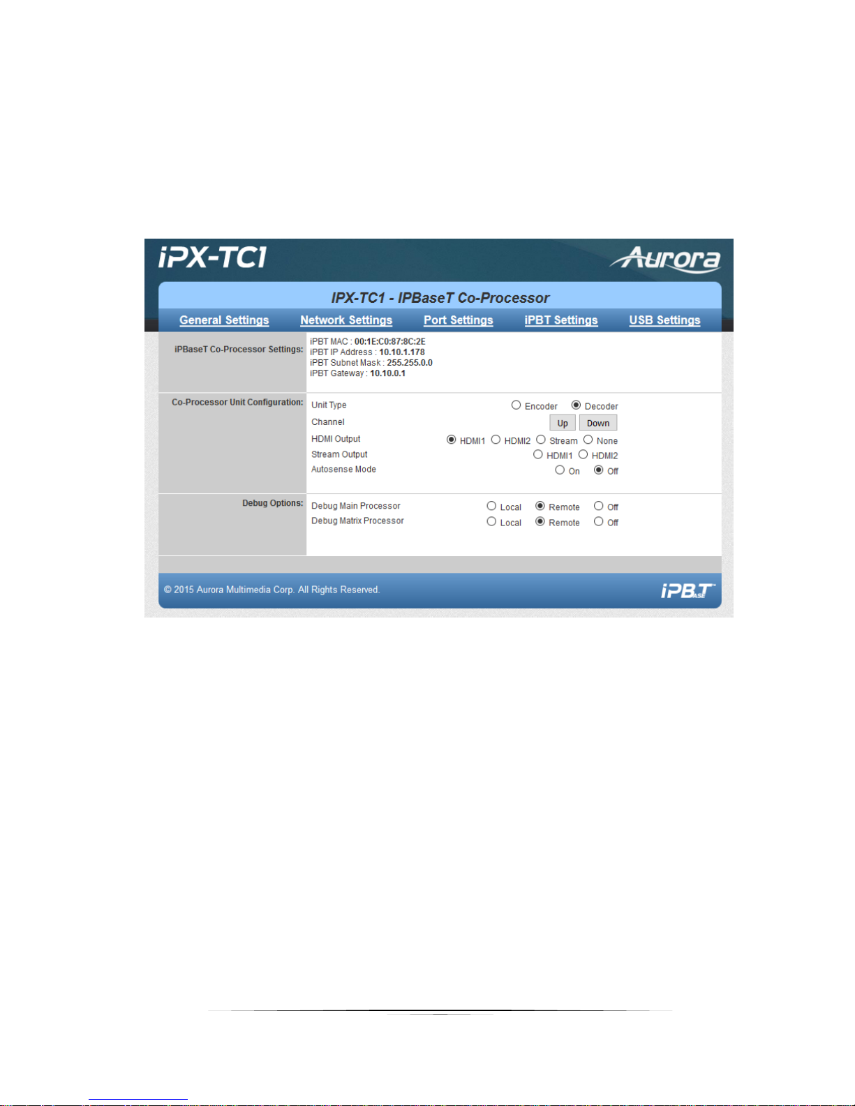
iPBT Settings
The iPBaseT Settings page is for the video streaming processor. It allows the viewing of the MAC, IP,
subnet, and gateway address. In addition, you can select the HDMI inputs and set debug mode in the
event diagnostics need to be performed.
Page 31
30
User Guide
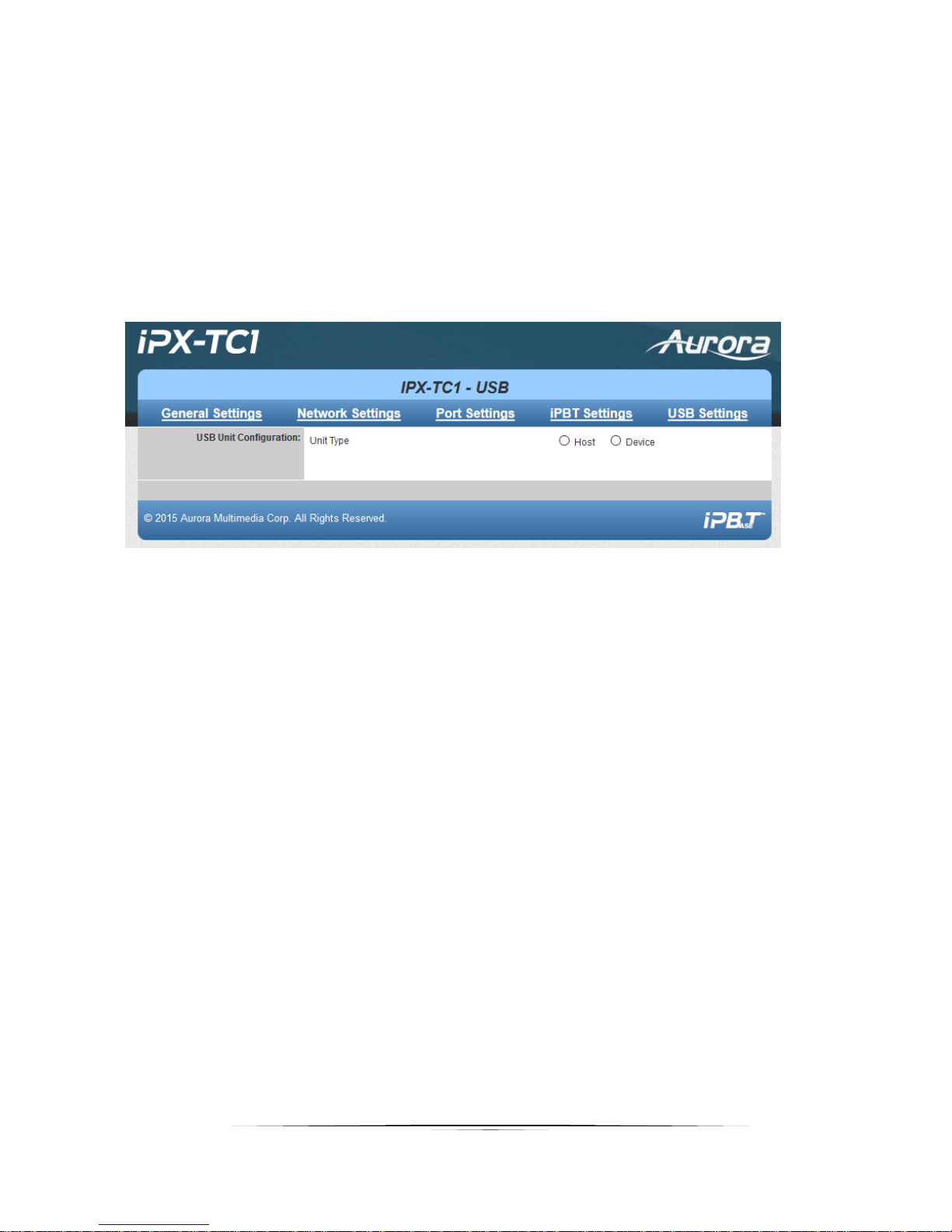
USB Settings
Allows viewing of current USB mode set by the API Server or IPBaseT Manager. Host mode is for a PC to
be connected to the USB port of IPX with a Type A to Type A cable (supplied with IPX-USB2 card). Device
mode is for USB memory sticks, mouse, keyboard, cameras, etc. to be connected to the IPX USB port.
Note: The USB settings will only work if the IPX-USB2 option card is installed.
Page 32
31
User Guide
APPLICATIONS
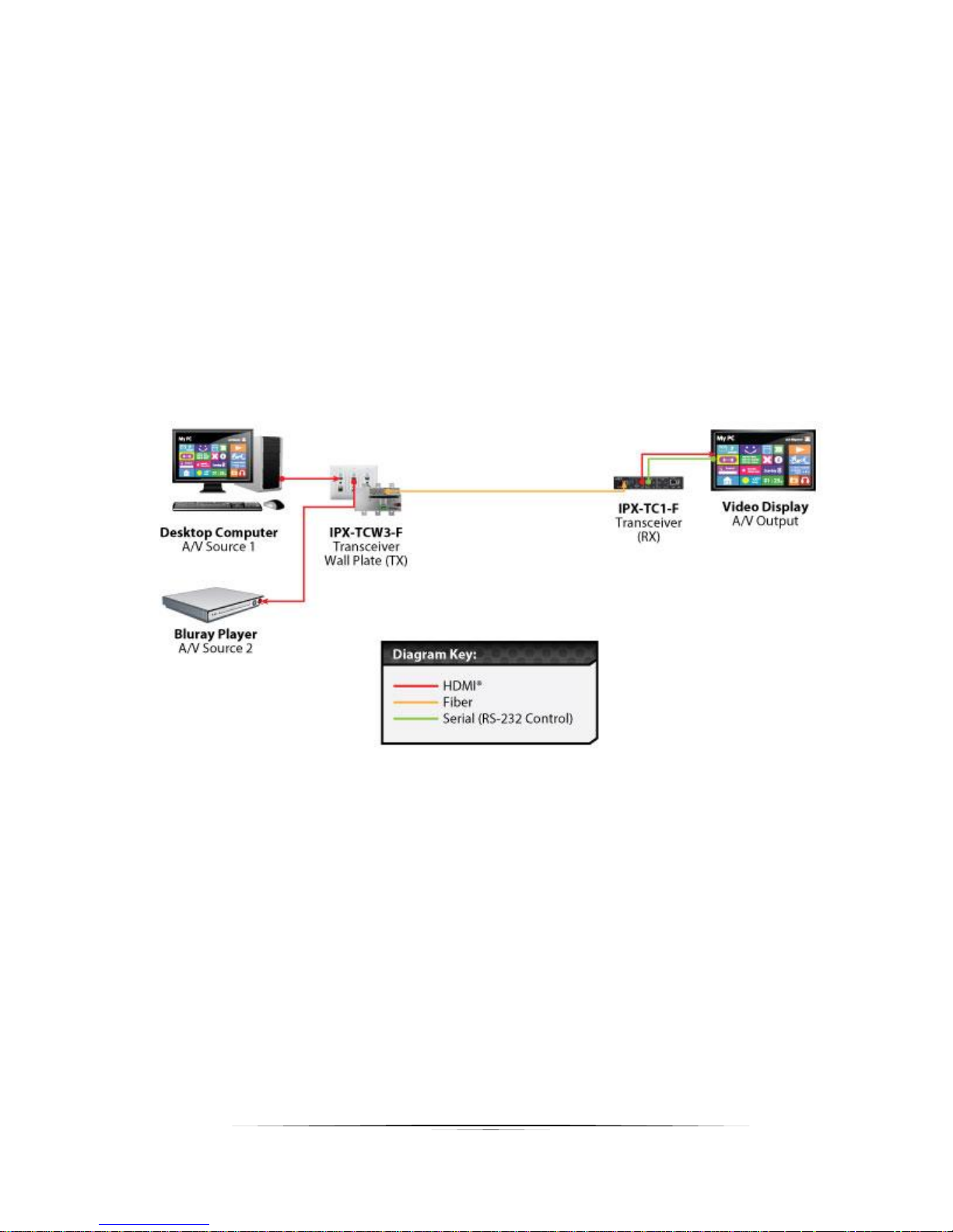
Example 1: IPX-TCW3 Configured as Transmitter to IPX-TC1 Configured Receiver
When the IPX Series is connected point to point, no configuration is required, as the units will auto
identify and make a tunnel between both ends for the video, audio, RS-232, IR, USB, and Ethernet. With
the copper version a maximum distance of 100m (328ft) can be achieved. With fiber cable depends on
multi-mode or single mode and can extend for miles, depending on the SFP+ module used. The most
common, OM3 multimode fiber, will travel about 300m (984ft).
Page 33
32
User Guide
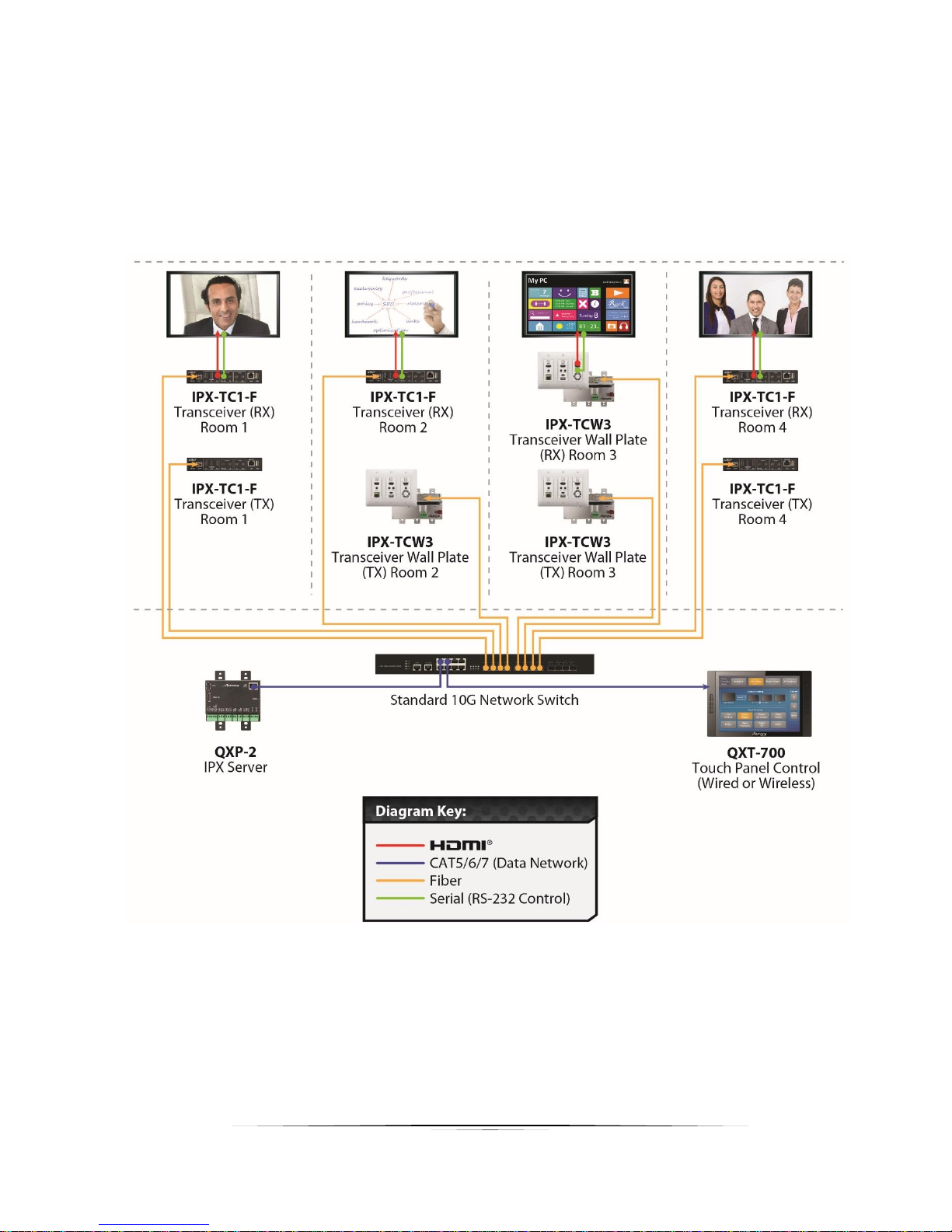
Example 2: IPX Multi-Room
The IPX Series is perfect for multi-room applications with its flexibility. A nearly unlimited number of
rooms can share video, audio, data, and control in real-time. The scalability is only limited by the size of
the network switch and infrastructure.
Page 34
33
User Guide
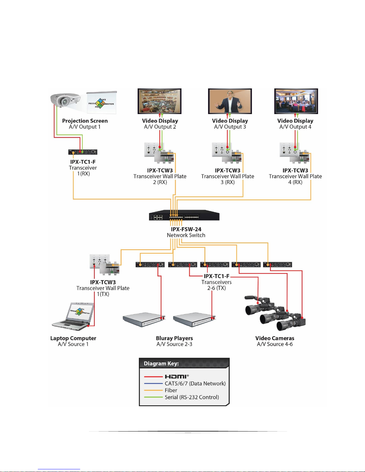
Example 3: Matrix - Multiple IPX to Multiple IPX
The IPX can take the place of any typical card cage matrix system, adding flexibility and performance
never seen before. Even features like seamless switching is no longer a premium.
Page 35
34
User Guide
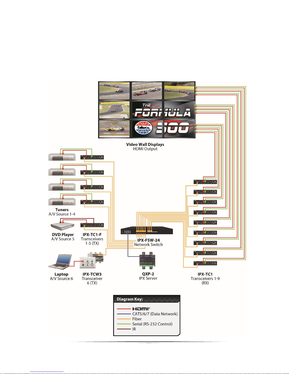
Example 4: Video-Wall
The IPX Series is capable of 4K video-walls. Up to 2x2 size can be created with 4K input and all with no
compression and zero latency for the IPX-TC1 and 16x16 for the IPX-TC2. It is important to read
Understanding the Basics section of this manual when specifying videowall usage.
Page 36
35
User Guide
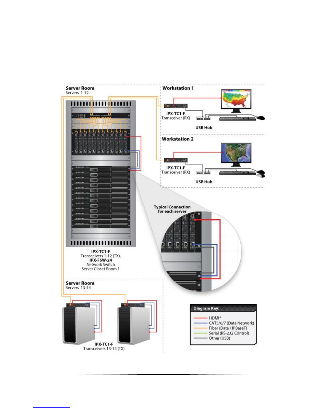
Example 5: KVM utilizing USB 2.0
Command & Control and NOC centers are perfect for the IPX Series, especially with the advanced break-
away switching and USB 2.0 running at a full 480Mbps. With the IPX it is no longer just keyboard and
mouse but full USB peripheral routing as well.
Page 37
36
User Guide
SOFTWARE
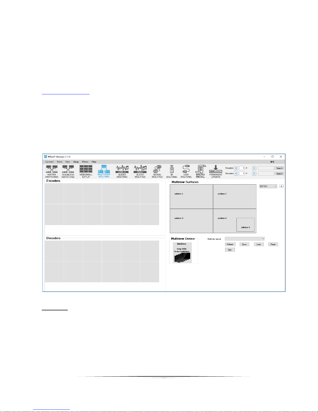
IPBaseT Manager PC Control Tool
The IPBaseT Manager is a Windows® based software available at the Aurora customer portal on
www.auroramm.com
IPBaseT Manager allows a user to control the various capabilities of IPX series products on a network.
While the IPBaseT Manager is a client software, the IPX Server (QXP-2-IPX Server Version) handles all
the communication handling and is the target for all communication. This allows for centralized
communications and the ability to run many clients on a network seamlessly.
Features
• Matrix Switching
• Seamless Matrix Switching
• Multi-view
• Video Wall Setup and Control
• Audio Break-away Routing
• RS-232 Routing & Control
Page 38

37
User Guide
• IR (Infrared) Remote Control Routing
• USB Routing
• Horizontal and Vertical Viewing
• Preset Store and Recall
• Connection Manager
• Advanced Debug Logging
• Touch Screen Friendly Layout
• Configuration File for Cloning Presets and Connections on Other PCs
• Multi-Server connections
For full detail of the IPBaseT Manager software tool and setup, the manual can be found at the Aurora
website www.auroramm.com
Page 39
38
User Guide
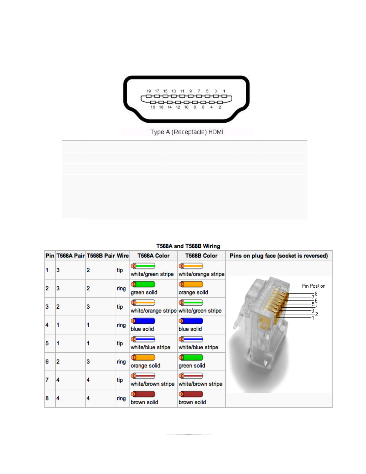
CONNECTOR PIN DEFINITION
HDMI
Pin 1 TMDS
Data2+
Pin
8
TMDS Data0 Sh
ield
Pin
15
SCL
Pin 2 TMDS Data2 Sh
ield
Pin
9
TMDS
Data0–
Pin
16
SDA
Pin 3 TMDS
Data2–
Pin
10
TMDS
Clock+
Pin
17
DDC/CEC Gr
ound
Pin 4 TMDS
Data1+
Pin
11
TMDS Clock Sh
ield
Pin
18
+5 V Powe
r
Pin 5 TMDS Data1 Sh
ield
Pin
12
TMDS
Clock–
Pin
19
Hot Plug
Detect
Pin 6 TMDS
Data1–
Pin
13
CEC
Pin 7 TMDS
Data0+
Pin
14
Reserved (N.C. on
device)
CAT5e/6/6A
Page 40
39
User Guide
RS-232
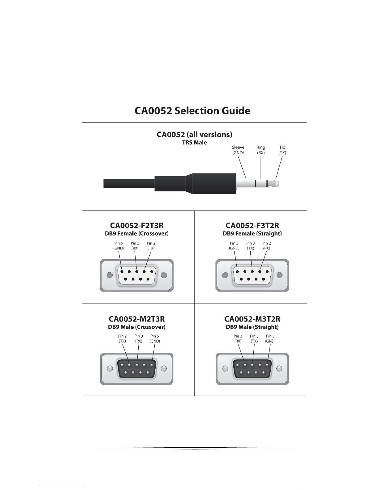
The RS-232 is a 3.5mm TRS connector. Tip is TX (output), ring is RX (input), and Sleeve is ground. To
simplify connections Aurora offers pre-molded RS-232 cables in null and none nulled in male and female
DB9.
Page 41
40
User Guide
IR (Infrared)
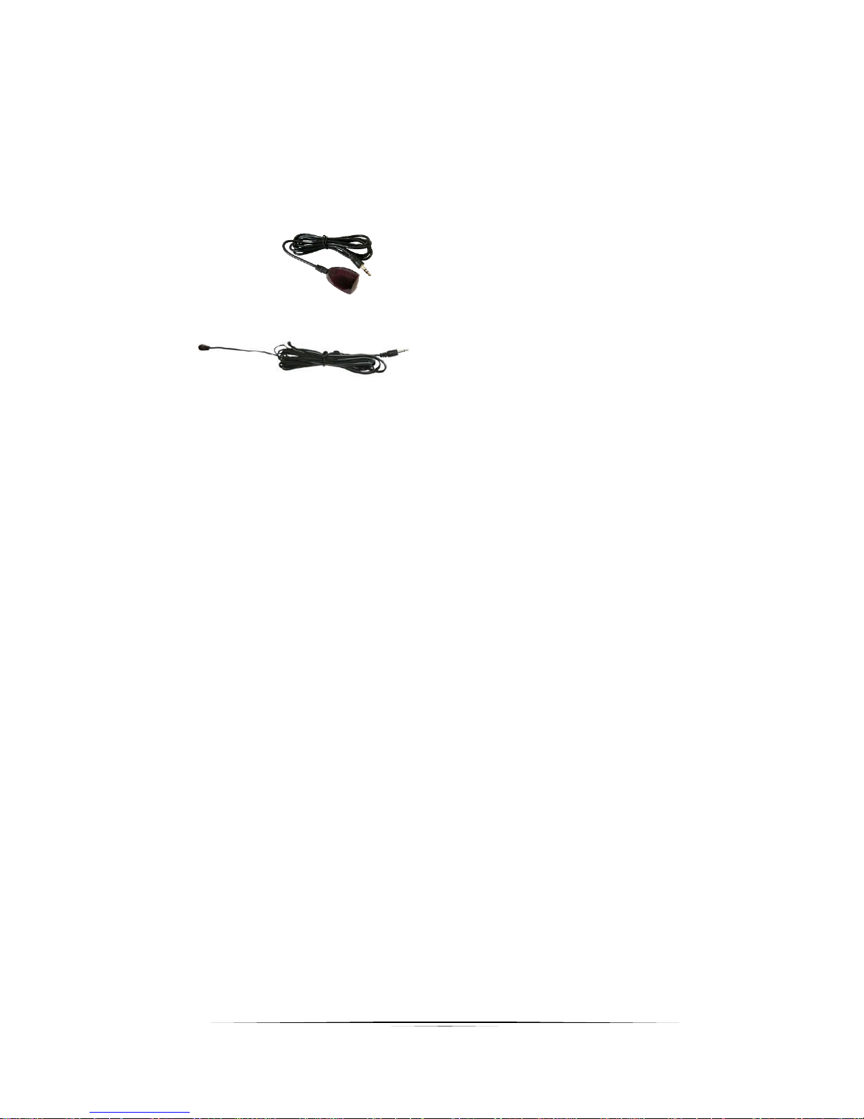
It will autosense a TS or a TRS connector to determine if an IR emitter (TS) or IR receiver (TRS) is
inserted. The IR receiver must be with carrier inverted to work. The tip is signal, ring is 5V, and sleeve is
ground.
• IR Receiver CA0026-1 (30kHz – 60kHz)
• IR Emitter CA0061-1
Page 42

41
User Guide
APPENDIX 1 Troubleshooting
It is advisable to make certain all units are using the latest firmware before troubleshooting.
Why IPBaseT Manager cannot find any devices?
• Check the IP Address of the QXP-2-IPX server and make certain it is connected on the same
network.
• Check the IP Address of the PC is set properly to work with the QXP-2-IPX server.
• Make certain the connection IP Address and port is set correctly in IPBaseT Manager.
• Check the IGMP Snooping status in Switch. This function should be enabled.
• Multiple servers are communicating at the same time. Only one server can communicate at a time
to the IPX units.
IPX Web Server is not responding
• Make certain every IPX unit has a unique IP Address set for the webserver. Disconnect unit from
10G network and connect PC directly to 1G LAN and check to see if webserver appears in browser.
If not trying restoring defaults and try again. Repeat this for every unit. Another method is using the
server to issue commands to change the webserver IP settings over the 10G.
IPX 1GbE LAN not working
• Make certain the 1GbE ports of different IPX units are not connect into the same Network/Ethernet
switch.
Display will not show a picture
• All devices are powered on.
• Unit is set properly for Decoder. LED status will show this.
• Check routing with IPBaseT Manager.
• A picture is achieved when connecting the source directly to the display.
• Display is set to the correct signal source input mode using display’s remote. Example, switching
to HDMI 1 if HDMI 1 interface is connected to the RX via a HDMI cable.
• All the cables are qualified.
• The Switch supports IGMP snooping and this function is enabled.
Display has image with wrong color
• Make certain to learn the EDID from the display and save into each units HDMI input ports.
• If different displays are used with the same source an EDID with a common denominator must be
used. For example, if on destination is 4K UHD and the other is 1080p and the 4K EDID is utilized,
the 1080p screen will not get an image if the source is 4K capable. In this case it would be better
to use a 1080p EDID.
Page 43

42
User Guide
Audio not working
• Make certain correct audio path is selected. The IPX can choose between analog input and HDMI.
• Verify correct EDID usage. If EDID has 5.1 surround sound listed and display cannot do 5.1 there
will be no audio. Lack of EDID will also cause a source to output DVI which lacks audio.
• Check volume on display or amplifier
IPX RS-232 control is not working
• Check wiring for RX, TX, and Ground. (IPX 3.5mm Tip is TX, Ring is RX, Sleeve is GND)
• Check the baud rate of the unit.
• Confirm the protocol being utilized with a terminal program.
Routing a source to multiple displays is tearing
• Check network switch is properly configured for IGMP
IPX Server is responding poorly
• Check network switch is properly configured for IGMP with snooping
Seamless Switching not working properly
• Seamless switching will only work if switching between two sources with the same resolution and
refresh rate.
• Seamless switching will not work between inputs on the same unit only between units.
• Seamless will only work with RGB/YCrCb 4:4:4. The EDID will determine the color space the source will put
out so changing the EDID could correct this issue.
• Seamless switching only works on progressive signals not interlaced.
• Ethernet switch does not support fast switching. This will cause a glitch when switching especially
with 4K. Netgear XS708E copper 10G switch does not support this mode. The switch will still be
instant but not as clean.
Displays not showing same video frame as others
• If displays are different brands this can happen as depending on the scaler circuitry utilized inside
the display and the amount of buffering used.
• If displays are different brands trying using same native resolution of the displays. Some displays
will not scale or use memory and just sync to the native signal.
Audio is different between displays or the analog output
• If displays are different brands this can happen based on the design. It is always ideal to use same
models for consistency or a central source for audio to keep in sync.
Page 44

43
User Guide
Videowall mode not working correctly
• As per the Understanding the Basics videowall section, some displays will not work well with the
IPX-TC1 based on bezel compensation or input resolution relative to the videowall size. Please
refer to that section. IPX-TC2 model does not have these limitations and is the recommended
model for Videowall usage.
Page 45

44
User Guide
APPENDIX 2 Firmware Update
For the latest firmware updates please go www.auroramm.com
You must be signed up to the Customer Portal in order to download firmware with
instructions on how to update.
APPENDIX 3 Protocol
For the latest protocol please go www.auroramm.com
You must be signed up to the Customer Portal in order to download IPX protocol. The
protocol is only available to authorized Aurora dealers.
Page 46
45
User Guide
APPENDIX 4 Recommended Cabling
The IPX series uses industry standard cabling for both fiber and copper and should abide
by network infrastructure standards. For the copper, unshielded cable is preferred for
optimal performance. While any properly made cable will work with the IPX series the
models below have been tested by Aurora with the IPX at full bandwidth and distance.
Fiber with copper for remote power
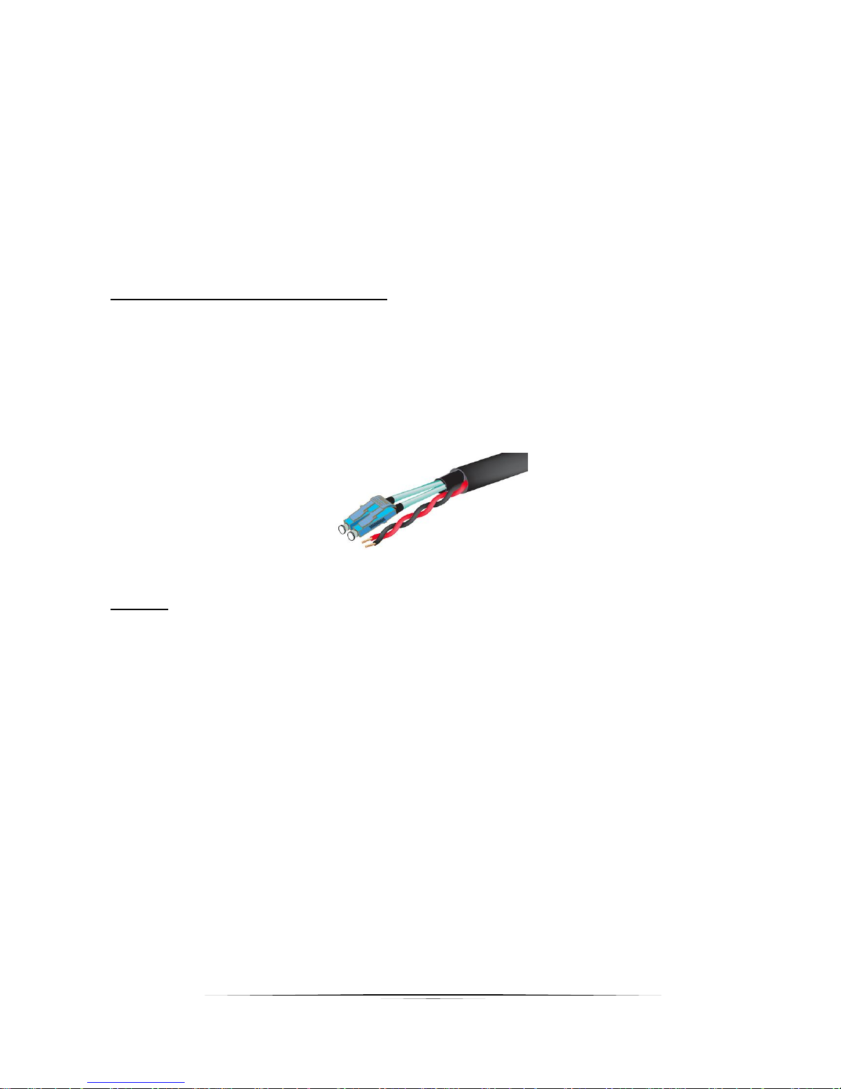
Manufacturer: West Penn Wire
FI-GIG-GIDY-xx (Dual OM3 Multi-Mode Terminated Fiber with LC Connectors + 18/2
Power Cable) Giggidy Fiber Cables are pre-terminated with LC Connectors and have a
Pulling Eye for easy pull and connectivity. Plenum Rated.
Note: Replace xx:75,100,125,165,230,330ft) Comes with Pulling Eye!
Copper
When using copper, you should not have any tight bends and make certain excess is
spooled as a figure 8. CAT6A will achieve a distance of 100m (330ft) with CAT6A, 55m
with CAT6, and 40m with CAT5e.
Manufacturer: West Penn Wire
4246A (4 Pair 23AWG Cat6A 10G Rated (UTP) Unshielded Twisted Pair .309” O.D
CMR Rated
254246A (4 Pair 23AWG Cat6A 10G Rated (UTP) Unshielded Twisted Pair .308” O.D
CMP Rated
Page 47

46
User Guide
APPENDIX 5 Recommended Network Switches
The IPX will work with most non-blocking, IGMP 10G network switch. Layer 3 will allow
more control, however, Layer 2 will work as well. It is highly recommended to
communicate with the representative of the desired network switch brand to confirm
configuration and capabilities. Below are some models that have been tested with the
IPX Series. For a more complete listing, the IPX Series Network Switch
Recommendations and Configuration guide can be found on the Aurora website.
www.auroramm.com
5.1 Switch Speed
The IPX Series requires the switch to be a 10 GbE.
IPX Series technology is used to transmit uncompressed video up to 4K along with
other AV signals such as audio, USB and control signals. For video alone, it means raw
bandwidth of about 4 Gb/sec for HD and 8 Gb/sec for 4K mean a bandwidth of around 6
GB/s, and that just for video. It is therefore easy to understand why the IPX requires 10
GbE network switches.
5.2 Packets Routing
To enable the transmission of a source to multiple destinations, IPX devices make use
of Multicast. The default behavior of layer 2 Ethernet switch is to broadcast those
packets which mean that every packet will be transmitted to all possible destinations.
This is why any network switch used with IPX Series has to support IGMP Snooping.
IPX end points use IGMP protocol to assign the end points into multicast groups and
the router uses IGMP snooping to efficiently route multicast packets only to receivers
that want to receive them.
Many switches have the IGMP Snooping feature disabled by default and manual
configuration is required. Often, a simple check mark near “Enable IGMP Snooping” is
the only thing needed to enable IGMP Snooping.
However, the implementation of IGMP Snooping is vendor specific and additional
configuration is often needed.
An Ethernet switch can be informed that a device wants to leave a multicast channel by
sending it a IGMP LEAVE GROUP packet. Once received, the time it takes for the
Page 48

47
User Guide
switch to apply the new configuration may vary from one switch to the other. Most
switches implement and include FASTLEAVE configuration option. When enabled, it
takes much less time for a particular port to leave a multicast group to assign the port to
a different multicast group. The end results are a noticeably shorter video switching
time. Aurora recommends to always enable the FASTLEAVE option when available.
With FASTLEAVE option, seamless switching is possible for 4K video sources. Without
FASTLEAVE option, 'seamless' switching is limited to 1080P 60 Hz video signals.
5.3 Ethernet Switch Configuration
The following list includes all network switch configuration options that Aurora
Engineers have come across so far. Look for these or similar options when configuring
your switch.
1. Enable IGMP Snooping
a. Must be enabled
2. Enable IGMP Snooping on VLAN 1
a. Must be enabled when all ports default to VLAN1
3. Filter/Drop unregistered Multicast traffic
a. If not applied, the behavior of the switch will be to broadcast multicast packets
if the switch has no known destination for that packet.
b. Must be enabled if found
4. Unregistered Multicast Flooding
a. Must be disabled if found
5. Filter Unregistered Multicast (different wording than number 4 above)
a. Must be enabled if found
6. Enable IGMP Query
7. Enable IGMP Query on VLAN1
8. Set IGMP Version to IGMP V2
a. Must be set if found
9. Enable FASTLEAVE on port X
a. This is optional. Should be enabled, if found
10. Enable FASTLEAVE for VLAN1
a. This is optional. Should be enabled if found
Page 49

48
User Guide
5.4 Ethernet Switch Models
The IPX Series Network Switch Recommendations and Configuration guide can be
found on the Aurora website. www.auroramm.com
Page 50

49
User Guide
APPENDIX 6 Technical Specifications
Model Name
IPX-TC1 & IPX-TCW3
Technical
Compression
Zero
Latency
Zero
HDMI Inputs
2
HDMI Outputs
1
Audio Analog
Stereo Line In/Out (3.5mm TRS Tip is Left, Ring is Right, Sleeve is Ground)
10G Fiber Ethernet
SFP+ (Single Mode or Multi-Mode)
10G Copper Ethernet
RJ-45 330ft with CAT 6A
LAN
RJ-45 10/100/1000M PoE (PSE)
Video Bandwidth
340MHz
Video support
Up to 4K2K 4:2:0 @60Hz
Audio support
Up to 32 channels & Break-away Capable
RS-232
Up to 115k Baud (3.5mm TRS Tip is TX, Ring is RX, Sleeve is GND)
IR
Bi-Directional (3.5mm TRS Tip is TX, Ring is 5V, Sleeve is GND)
USB Connector
USB 2.0 Type A (Host or Device Software Selectable)
Expansion Port
SO-DIMM for ExtermeUSB® or Dante® Options
Interface
IR or Keypad, Webserver, IPBaseT Manager
Mechanical
Housing
Black Aluminum Enclosure
Dimensions
[L x W x H]
Box Versions: 175 x 102 x 33.3mm [6.875" x 4" x 1.31"]
Wall Versions: 3 Gang 5.54” x 2.83” (4.331” with mounting tabs) x 1.404”.
Wall box portion depth 1.404” without option card and 2.25" with option card.
Weight
1.13g [2.5lbs]
Mounting
Optional: Rack mount vertical, Rack mount horizontal, Under table mount
Wall-mounting Decora® 3 Gang
Power supply
48V DC (2 pin Euro) or PoE (LAN)
Power consumption
13 Watts (-F) / 15 Watts (-C)
Operation temperature
0~40C [32~100F]
Storage temperature
-20~60C [-4~140F]
Relative humidity
20~90% RH [no condensation]
Package Contents
1x IPX-TC1 (–F or –C)
Specifications subject to change without notice.
Page 51

50
User Guide
APPENDIX 7 Warranty
Limited 3 Year Warranty
Aurora Multimedia Corp. (“Manufacturer”) warrants that this product is free of defects in both materials and
workmanship for a period of 3 years as defined herein for parts and labor from date of purchase. This Limited Warranty
covers products purchased in the year of 2009 and after. Motorized mechanical parts (Hard Drives, DVD, etc.),
mechanical parts (buttons, doors, etc.), remotes and cables are covered for a period of 1 year. Touch screen displays
are covered for 1 year; touch screen overlay components are covered for 90 days. Supplied batteries are not covered
by this warranty. During the warranty period, and upon proof of purchase, the product will be repaired or replaced (with
same or similar model) at our option without charge for parts or labor for the specified product lifetime warranty period.
This warranty shall not apply if any of the following:
A. The product has been damaged by negligence, accident, lightning, water, act-of-God or mishandling; or,
B. The product has not been operated in accordance with procedures specified in operating instructions: or,
C. The product has been repaired and or altered by other than manufacturer or authorized service center; or,
D. The product's original serial number has been modified or removed: or,
E. External equipment other than supplied by manufacturer, in determination of manufacturer, shall have
affected the performance, safety or reliability of the product.
F. Part(s) are no longer available for product.
In the event that the product needs repair or replacement during the specified warranty period, product should be
shipped back to Manufacturer at Purchaser's expense. Repaired or replaced product shall be returned to Purchaser
by standard shipping methods at Manufacturer's discretion. Express shipping will be at the expense of the Purchaser.
If Purchaser resides outside the contiguous US, return shipping shall be at Purchaser's expense.
No other warranty, express or implied other than Manufacturer's shall apply.
Manufacturer does not assume any responsibility for consequential damages, expenses or loss of revenue or property,
inconvenience or interruption in operation experienced by the customer due to a malfunction of the purchased
equipment. No warranty service performed on any product shall extend the applicable warranty period. This warranty
does not cover damage to the equipment during shipping and Manufacturer assumes no responsibility for such
damage. This product warranty extends to the original purchaser only and will be null and void upon any assignment
or transfer.
Page 52

51
User Guide
Aurora Multimedia Corp.
205 Commercial Court
Morganville, NJ 07751
Phone: 732-591-5800 Fax: 732-591-6801
www.auroramm.com
 Loading...