

Page 1
i
Manual Number: 170408
USERS GUIDE
IPX Series
Network Switch Recommendations & Configuration
10Gbps Network Switch Configurations
Page 2

i
User Guide
TABLE OF CONTENTS
RECOMMENDED NETWORK SWITCHES ............................................................................... 1
1.1 Switch Speed .................................................................................................................................. 1
1.2 Packets Routing .............................................................................................................................. 1
1.3 Ethernet Switch Configuration ........................................................................................................ 2
1.4 Ethernet Switch Models .................................................................................................................. 3
CONFIGURATIONS ................................................................................................................... 5
Switch Login & Connections ................................................................................................................. 5
Aurora IPX-FSW Series ........................................................................................................................ 5
BlackBox ............................................................................................................................................... 6
Netgear ProSAFE XS708E ................................................................................................................... 7
Netgear ProSAFE XS712T ................................................................................................................... 8
Netgear ProSAFE XS728T ................................................................................................................. 12
Netgear M7300-24XF XSM7224S ...................................................................................................... 14
Extreme Network Summit X670 Series .............................................................................................. 15
Arista Networks 7050X Series ............................................................................................................ 15
Huawei Cloud Engine Series .............................................................................................................. 17
D-Link DXS-1210-12TC ...................................................................................................................... 19
Ubiquiti EdgeSwitch16 XG Model ES-16-XG ..................................................................................... 21
Edge-Core AS5700-54X-EC ............................................................................................................... 22
Page 3

1
User Guide
RECOMMENDED NETWORK SWITCHES
The IPX will work with most non-blocking, IGMP 10G network switch. Layer 3 will allow
more control, however, Layer 2 will work as well. It is highly recommended to
communicate with the representative of the desired network switch brand to confirm
configuration and capabilities. Below are some models that have been tested with the
IPX Series.
1.1 Switch Speed
The IPX Series requires the switch to be a 10 GbE.
IPX Series technology is used to transmit uncompressed video up to 4K along with
other AV signals such as audio, USB and control signals. For video alone, it means raw
bandwidth of about 4 Gb/sec for HD and 8 Gb/sec for 4K mean a bandwidth of around 6
GB/s, and that just for video. It is therefore easy to understand why the IPX requires 10
GbE network switches.
1.2 Packets Routing
To enable the transmission of a source to multiple destinations, IPX devices make use
of Multicast. The default behavior of layer 2 Ethernet switch is to broadcast those
packets which mean that every packet will be transmitted to all possible destinations.
This is why any network switch used with IPX Series has to support IGMP Snooping.
IPX end points use IGMP protocol to assign the end points into multicast groups and
the router uses IGMP snooping to efficiently route multicast packets only to receivers
that want to receive them.
Many switches have the IGMP Snooping feature disabled by default and manual
configuration is required. Often, a simple check mark near “Enable IGMP Snooping” is
the only thing needed to enable IGMP Snooping.
However, the implementation of IGMP Snooping is vendor specific and additional
configuration is often needed.
An Ethernet switch can be informed that a device wants to leave a multicast channel by
sending it a IGMP LEAVE GROUP packet. Once received, the time it takes for the
switch to apply the new configuration may vary from one switch to the other. Most
switches implement and include FASTLEAVE configuration option. When enabled, it
takes much less time for a particular port to leave a multicast group to assign the port to
Page 4

2
User Guide
a different multicast group. The end results are a noticeably shorter video switching
time. Aurora recommends to always enable the FASTLEAVE option when available.
With FASTLEAVE option, seamless switching is possible for 4K video sources. Without
FASTLEAVE option, 'seamless' switching is limited to 1080P 60 Hz video signals.
1.3 Ethernet Switch Configuration
The following list includes all network switch configuration options that Aurora
Engineers have come across so far. Look for these or similar options when configuring
your switch.
1. Enable IGMP Snooping
a. Must be enabled
2. Enable IGMP Snooping on VLAN 1
a. Must be enabled when all ports default to VLAN1
3. Filter/Drop unregistered Multicast traffic
a. If not applied, the behavior of the switch will be to broadcast multicast packets
if the switch has no known destination for that packet.
b. Must be enabled if found
4. Unregistered Multicast Flooding
a. Must be disabled if found
5. Filter Unregistered Multicast (different wording than number 4 above)
a. Must be enabled if found
6. Enable IGMP Query
7. Enable IGMP Query on VLAN1
8. Set IGMP Version to IGMP V2
a. Must be set if found
9. Enable FASTLEAVE on port X
a. This is optional. Should be enabled, if found
10. Enable FASTLEAVE for VLAN1
a. This is optional. Should be enabled if found
Page 5

3
User Guide
1.4 Ethernet Switch Models
The following is a list of 10G Ethernet switch models that have been verified to date.
Check with Aurora to see if any others may have been added at a later time relative to
the manual revision date.
Aurora IPX-FSW Series Fiber 10G
IPX-FSW-8 8 Port Switch Layer 3 with 8 1G RJ-45 ports
IPX-FSW-12 12 Port Switch Layer 3 with 8 1G RJ-45 Ports
IPX-FSW-24 24 Port Switch Layer 3 with 4 1G RJ-45 Ports
Arista Networks
7050SX-72 72 Port SFP+ 10G Fiber Switch
7050SX-96 96 Port SFP+ 10G Fiber Switch
7050SX-128 128 Port SFP+ 10G Fiber Switch
7050TX-64 64 Port 10G Copper Switch
7050TX-72 72 Port 10G Copper Switch
7050TX-96 96 Port 10G Copper Switch
7050TX-128 128 Port 10G Copper Switch
Extreme Networks
X670-48T 48 Port Copper Switch
X670-48X 48 Port SFP+ Fiber Switch
Huawei
CE6851-48S6Q-HI (48*10G Base-X SFP+ Fibber Ports + 6*40G QSFP+ Ports)
CE8860-4C-EI (4 Sub Card Slots)
Sub card for CE8860
CE88-D24S2CQ (24*10G Base-X SFP+ Fiber Ports+ 2*40G/100G QSFP+ Ports)
CE6850-48T6Q-HI (48*10G Base-T Copper Ports+ 6*40G QSFP+ Ports)
CE8860-4C-EI (4 Sub Card Slots)
Sub card for CE8860
CE88-D24T2CQ (24*10G Base-T Copper Ports+ 2*40G/100G QSFP+ Ports)
Page 6

4
User Guide
Netgear Copper 10G
XS708E 8 Port ProSAFE Plus Switch (Note: This is a layer 2 switch and does not have
fast switching. IPX Seamless switch mode will work however at times you may
see a slight glitch in the image.) One port is a shared 10G SFP+ Fiber Ports.
XS708T 8 Port ProSAFE Smart Managed Switch with 1 shared 10G SFP+ Fiber Ports.
XS712T 12 Port ProSAFE Smart Managed Switch with 2 shared 10G SFP+ Fiber Ports.
XS728T 28 Port ProSAFE Smart Managed Switch 24 Copper and 4 non-shared 10G
SFP+ Fiber Ports
XS748T 48 Port ProSAFE Smart Managed Switch 44 Copper and 4 non-shared 10G
SFP+ Fiber Ports
Page 7

5
User Guide
CONFIGURATIONS
Switch Login & Connections
Login
You must first log onto the switch with administrator right. Follow the switch manufacturer
manual to do so. It will also give you the default Admin password.
Console Port
Some manufacturers use RS-232 / “Console port” for switch configuration and dedicated
console cable which is different from a standard Cat X (RJ45) cable.
Ethernet
Other manufacturers go through standard 1Gbe compatible port for switch configuration. If this
is the case, the manufacturer will give you the default “IP Address” of the switch. Make sure
your network adaptor has an IP Address in the same network.
Depending on login method above, switch configuration will be done either through a Web
Browser or a Telnet Client.
Aurora IPX-FSW Series
The Aurora IPX-FSW Series is designed to work out of the box as it is pre-configured. To confirm
that the default configuration is correct or if settings have been changed inadvertently, open a
console (RS232 baud rate 38400) and type the following commands at the prompt:
Switch> enable
Switch# show ip igmp snooping mrouter -> expected output: IGMP Snooping Enabled
Switch# show ip igmp snooping fast-leave -> expected output: IGMP Snooping fast-leave is
enabled
Page 8
6
User Guide
BlackBox
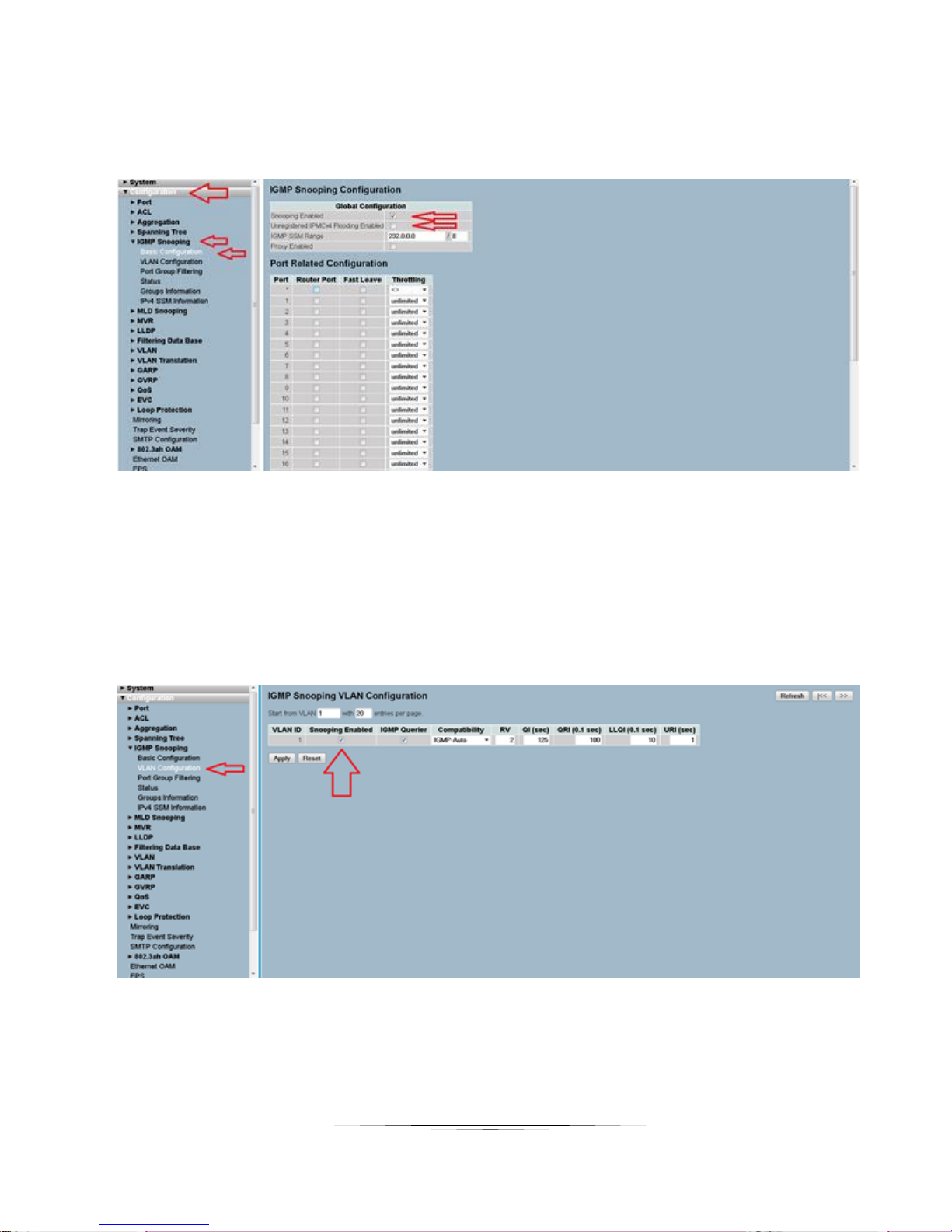
1. Go to the “Configuration” / “IGMP Snooping” / “Basic Configuration” tab as shown in
next screen shot:
2. Make sure “Snooping Enabled” is checked.
3. Make sure “Unregistered IPMCv4 Flooding Enabled” is NOT checked.
4. After the changes are made, go at the bottom of the page and click the “Apply”
button.
5. Next, go to the “VLAN Configuration” tab as showed in next screen shot:
6. Make sure “Snooping Enabled” is checked, and click “Apply”.
Page 9
7
User Guide
Netgear ProSAFE XS708E
This switch does not support FASTLEAVE option however there is a XS708T available that does.
While it supports 'seamless' switching for 1080P video resolutions it is not capable to support
seamless' switching for 4K30 resolutions and higher.
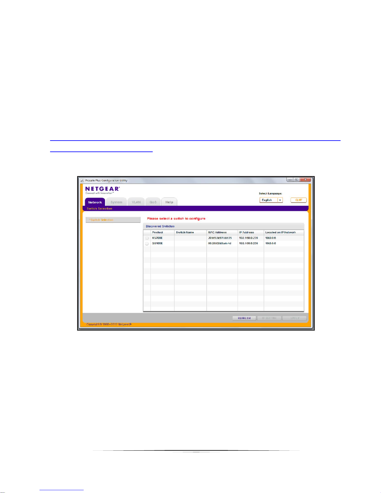
To configure the XS708E, use the ProSAFE Plus Switch Utility that is found on the Resource CD
shipped with ProSAFE PLUS switch. The utility can be installed on any Windows computer on
the same network as the switches to be managed. The user manual for the switch utility can
be found here
http://www.downloads.netgear.com/files/GDC/GS105E/ProSAFE%20Plus%20Switch%20Utility%
20User%20Guide_21Dec2012.pdf
Running the tool will list discovered switches as shown here below
Select the switch you want to configure and a switch from the list and press the Apply button on
the bottom right of the screen.
To enable Multicast:
• Select 'Systems' tab and from there select 'Multicast' sections
• In the IGMP Snooping Status list, select Enable and click Apply
• In the Block Unknown Multicast Address list, select Enable and click Apply
• You can also change the VLAN for which the IGMP snooping is enabled. In the
VLAN ID Enabled for IGMP Snooping field, enter a valid ID and click Apply. This field
Page 10

8
User Guide
is dimmed if VLAN is not enabled.
To enable VLAN:
• Select VLAN Tab
• Select Port Based and select Enable
• Select Yes if a message appears asking if you want to delete previous VLAN settings
• For each port to be added to the new group, enter the ID of the VLAN group
Netgear ProSAFE XS712T
To configure the XS712T, use the Smart Control Center Utility that is found on the Resource CD
shipped with ProSAFE Smart switch. The utility can also be downloaded directly from here
http://support.netgear.com/product/XS712T. The utility can be installed on any Windows
computer on the same network as the switches to be managed. The product guide and
software manual for the switch utility are also located at
http://support.netgear.com/product/XS712T
If the switch is connected to DHCP server make sure that the computer is also set to DHCP
mode and then run the utility and use the discover button to find the switch.
If you are using a static IP address in your network, configure the switch IP address before
connecting the switch to your network. The default IP address of the switch is 192.168.0.239.
Set up the computer with a static IP address in the 192.168.0.x subnet and connect it to the
switch and run the utility.
To configure the switch to work with IPX Series type devices, follow the instruction below to
setup VLAN and to enable both Multicasting and IGMP snooping.
1. If not available, create VLAN ID #1.
2. Once “VLAN ID” and “VLAN Name” fields are filled as showed, press “Apply” on the
lower right of the screen.
Page 11

9
User Guide
3. Go to the "Multicast" tab.
4. Select VLAN ID #1 and select “Filter Unregistered” in the drop- down list.
5. Press Apply in the lower right.
6. While in Multicast section, go to “Multicast Router Configuration”
7. Make sure that “Multicast Router” option is disabled for all ports.
8. Press “Apply” if you changed anything.
Page 12

10
User Guide
Next, go to “IGMP Snooping Configuration section”
9. Enabling IGMP Snooping. Both “IGMP Snooping Status” and "Validate IGMP IP header”
need to be enabled
10. Press “Apply”
11. Now, go to “IGMP Snooping VLAN Configuration”
12. Fill the row as shown below
Page 13

11
User Guide
13. Press “ADD” in the lower right of the screen.
14. Still in Multicast section, go to “IGMP Snooping Interface Configuration”.
15. Select all ports as shown below.
16. Fill the first row as shown below.
17. Press Apply on the lower right.
Page 14

12
User Guide
Netgear ProSAFE XS728T
Setup PC/Laptop that's used to for setup to 192.168.0.200 / 255.255.255.0 / 192.168.0.1.
Log into the switch using its IP address (if set to static) or its default IP, 192.168.0.239. Default
password is "password".
1/ Reset the switch to factory defaults (Maintenance --> Factory Default) to ensure all settings
are reset. If IP is unknown, factory defaults can be set by press and hold "Factory Defaults"
button for 2s or longer.
2/ Create VLAN 1 (default) if no VLAN is available (Switching --> VLAN).
3/ IGMP Snooping Configuration: have both IGMP Snooping Status and Block Unknown
Multicast Address enabled.
Page 15

13
User Guide
4/ IGMP Snooping VLAN Configuration: set the parameters as shown in picture.
Page 16

14
User Guide
Netgear M7300-24XF XSM7224S
Login into the switch and execute those commands:
(The left column is the prompt you should get. Right column is the command to have to type)
Switch> enable
Switch# configure
Switch (Config)# set igmp
Switch (Config)# set igmp unknow-multicast filter
Switch (Config)# exit
Switch# vlan database
Switch (Vlan)# set igmp 1
Switch (Vlan)# set igmp fast-leave 1
Switch (Vlan)# exit
Switch# copy system:running-config nvram:startup-config
Switch# show igmpsnooping
Switch# show igmpsnooping 1
Page 17

15
User Guide
Extreme Network Summit X670 Series
Aurora has tested two (2) Extreme Networks X670 Series switches in its lab; X670V-48t with 48
10GBase-T interfaces and X670-48x with 48 SFP+ interfaces. Other switches in this series
share the same firmware and should work as well with Aurora IPX Series based devices.
This includes:
• X670-G2-48x-4q
• X670-G2-72x
• X670V-48t
IGMP snooping is enabled by default for these switches. Fast Leave features should be
enabled. This allows IPX Series to switch faster and enables 'Seamless' switching.
Do the following to enable fast leave:
• Open a console (RS232 baud rate 9600)
• Login: admin
• Password: <enter password>
• To find the <VLAN_NAME> type: show igmp snooping
The vlan name is reported in the first column. Enter the following commands using the return
vlan_name
• configure igmp snooping leave-timeout 0
• enable igmp snooping vlan <VLAN_NAME> fast-leave
To save the configuration enter:
• save configuration primary
Arista Networks 7050X Series
Aurora has tested and validated the Arista 7050SX-64 in its lab. Since same firmware is used in
all 7050X series switches, other switches in the series should work as well. This includes the
following fiber and copper switches
Fiber:
• 7050SX-72
• 7050SX-96
Page 18

16
User Guide
• 7050SX-128
Copper:
• 7050TX-64
• 7050TX-72
• 7050TX-96
• 7050TX-128
Configuration is done through serial port. To configure any of the 7050X switches do the
following:
• Through the serial port, log into switch with default admin password
o Username admin
o No password
• To enable config mode type:
o enable
o configure terminal
o interface management 1
o ip address 192.168.2.201/24
o end
• To enter into switch config mode type:
o enable
o conf
• (You should now see this prompt)
o localhost(config)#
• To change the operating mode to store and forward:
o switch forwarding-mode store-and-forward
• To enable the IGMP querier type:
o ip igmp snooping vlan 1 querier address 192.168.2.99
o ip igmp snooping vlan 1 querier
o show ip igmp snooping querier
o show ip igmp snooping querier status
The switch is now properly configured.
Page 19

17
User Guide
Huawei Cloud Engine Series
Aurora has tested and validated the Huawei Cloud Engine Series Switches. Since same
firmware is used in all CE685X-HI and CE8800 series switches, other switches in the series
should work as well. This includes the following fiber and copper switches
Fiber:
• CE6851-48S6Q-HI (48*10G Base-X SFP+ Fibber Ports + 6*40G QSFP+ Ports)
• CE8860-4C-EI (4 Sub Card Slots)
o Sub card for CE8860
▪ CE88-D24S2CQ (24*10G Base-X SFP+ Fiber Ports+ 2*40G/100G QSFP+ Ports)
Copper:
• CE6850-48T6Q-HI (48*10G Base-T Copper Ports+ 6*40G QSFP+ Ports)
• CE8860-4C-EI (4 Sub Card Slots)
o Sub card for CE8860
▪ CE88-D24T2CQ (24*10G Base-T Copper Ports+ 2*40G/100G QSFP+ Ports)
Configuration is done through serial port. To configure any of the Cloud Engine switches do
the following:
• Through the serial port, log into switch
o No username admin
o No password
• To enable config mode type:
o system-view immediately
o interface MEth 0/0/0
o ip address 192.168.2.201 24
o quit
• To enter into switch config mode type:
o system-view immediately
• (You should now see this prompt)
o [HUAWEI]
• To change the operating mode to store and forward:
Page 20

18
User Guide
o assign forward mode store-and-forward
• To enable the IGMP querier type:
o [HUAWEI]igmp snooping enable
o [HUAWEI]vlan 1
o [HUAWEI-vlan1]igmp snooping enable
o [HUAWEI-vlan1]igmp snooping querier enable
o [HUAWEI-vlan1]quit
o [HUAWEI]acl 2000
o [HUAWEI-acl4-basic-2000]rule permit source 192.168.2.99 0
o [HUAWEI-acl4-basic-2000]rule deny source any
o [HUAWEI-acl4-basic-2000]quit
o [HUAWEI-vlan1]igmp snooping query ip –source-policy 2000
o [HUAWEI]Save
o display igmp snooping querier vlan 1
o display igmp snooping statistics vlan 1
The switch is now properly configured.
For more information,
CE6850-HI
http://e.huawei.com/en/products/enterprise-networking/switches/data-center-switches/ce6800
CE8800
http://e.huawei.com/en/products/enterprise-networking/switches/data-center-switches/ce8800
Page 21

19
User Guide
D-Link DXS-1210-12TC
D-Link DXWS-1210-12TC is an inexpensive hybrid 10G switch with up to 12 concurrent ports.
This is a smart managed switch that is entirely configured through web-browser interface. The
switch has 8 10GBaseT ports, 2 SFP+ ports and 2 ports that are mutually exclusive 10GBaseT or
SFP+ ports.
Make sure that switch is using recent firmware 1.10.013 or later.
Use the following steps to configure the switch for use with IPX Series devices
1. Connect your computer to any unused switch port. Use any browser to login into the
switch. To login your computer needs to be on the same subnet as the switch. Consult
the switch manual for more information. On first login you will be prompted to
set/change default switch password.
2. Enable IGMP snooping by navigating to L2 Features - L2 Multicast Control – IGMP
Snooping – IGMP Snooping settings
3. Change the IGMP global setting to 'Enabled and press the 'Apply' button afterward
Page 22

20
User Guide
4. While still in the IGMP Snooping Settings page, go to the detailed settings and press the
'Edit' button
5. Enable FastLeave
6. Enable Querier state and select Version 2
7. Press Apply
8. Finally go to L2 Features – L2 Multicast Control – Multicast Filtering and select 'Filter
Unregistered' from the drop down menu.
9. Press Save to Save the switch configuration.
10. The switch is now properly configured.
Page 23

21
User Guide
Ubiquiti EdgeSwitch16 XG Model ES-16-XG
The Ubiquiti ES-16-XG is an inexpensive 10G switch which seems to give a lot for very little. It
has 12 Copper and 4 Fiber 10G ports.
After login to the web interface, do the following
1. Go into page Switching\IGMP Snooping\Configuration and activate IGMP snooping globally.
1. Enable: Admin Mode
2. Click Submit button
2. Go into page Switching\IGMP Snooping\Interface Configuration to activate IGMP Snooping
and Fast Leave for each interface
1. Choose Display ALL rows
2. Check the first Check Box (on the left of Interface) to check select all interface at once
3. Click Edit button
1.Enable: Admin Mode
2. Enable: Fast Leave Admin Mode
3. Click Submit button
3. Go into page Switching\IGMP Snooping\VLAN Status to enable Fast Leave on VLAN
1. Click Add button to Add VLAN
1. Enable: Fast Leave Admin Mode
Page 24

22
User Guide
2. Click Submit button
4. Save Switch configuration
1. Click on Save Configuration button (top right)
Edge-Core AS5700-54X-EC
The Edge-Core AS5710-54X-EC is modestly priced, high performance 10G switch from Edge-Core
Networks. AS5710-54X-EC has 48x 10G SFP+ ports with 6x 40G QSFP+ uplinks.
To configure the switch to work with the IPX Series, please follow the instruction below to setup
both Multicasting and IGMP snooping to VLAN 1.
• Follow the instructions in the CLI command manual “AS5710-54X-EC_CLI_2016-03-25.pdf” on
how to login to the console of this switch in order to set the IP address, username, and
password.
• Login to the web panel of this switch by opening your browser, entering the IP address of this
switch, and then logging in with your username & password
• Once you are logged into your web panel, please make sure that the each of the pages below
are configured the same as in your switch. After making changes to any page, please don’t
forget to press on the APPLY button
Multicast > IGMP Snooping > General
Start with enabling IGMP snooping as illustrated in figure below
Page 25

23
User Guide
Multicast > IGMP Snooping > Multicast Router
This switch requires you to create a Multicast router port available. In our example, we
configured port 48 as the Mulitcast router. This means you cannot connect any device to port
48.
This is illustrated in figure below:
Page 26

24
User Guide
After configuring your desired port, this section should now look like this
Multicast > IGMP Snooping > IGMP Member
Page 27

25
User Guide
Multicast > IGMP Snooping > Interface
Select action “Configure VLAN” and configure it as illustrated below.
Next select action “Configure Interface and enable all of the ports that the IPBaseT devices will
be connected to as illustrated below
Once the above 2 pages are configured, this section should now look like this
Page 28

26
User Guide
Multicast > IGMP Snooping > Forwarding Entry
Page 29

27
User Guide
Multicast > IGMP Snooping > Filter
Select Step “Configure General”
Select “Configure Profile”
Page 30

28
User Guide
Select “Configure Interface” and configure all of the desired ports as in this image below
System > File
After making all these changes, they are all stored in the file “startup1.cfg”
Please copy this and name the copy as an example to “AptoVision.cfg” and make this the
startup configuration file by doing the following:
Page 31

29
User Guide
Page 32

30
User Guide
Aurora Multimedia Corp.
205 Commercial Court
Morganville, NJ 07751
Phone: 732-591-5800 Fax: 732-591-6801
www.auroramm.com
 Loading...