

Page 1
Manual Number: 140731
USERS GUIDE
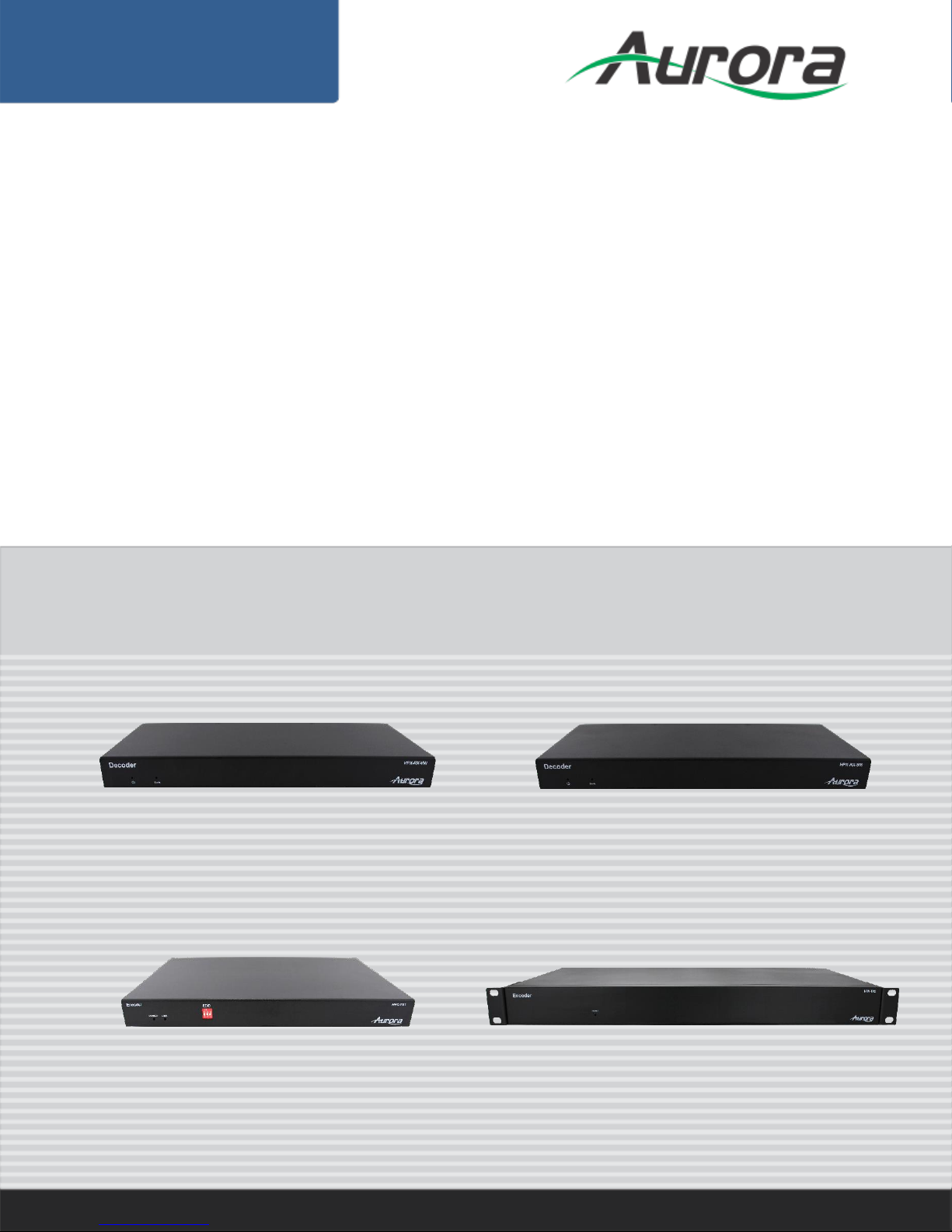
HPX Series
HPX-TX1 / HPX-TX2 / HPX-RX-SM / HPX-RX-VW
H.264 IP Distribution
HPX-TX2
HPX-TX1
HPX-RX-VW
HPX-RX-SM
i
Page 2

User Guide
The lightning symbol in the triangle is used to alert you to the presence of dangerous voltage
inside the product that may be sufficient to constitute a risk of electric shock to anyone opening
the case. It is also used to indicate improper installation or handling of the product that could
damage the electrical system in the product or in other equipment attached to the product.
The exclamation point in the triangle is used to alert you to important operating and maintenance
instructions. Failure to follow these instructions could result in injury to you or damage to the
product.
SAFETY INSTRUCTIONS
Please review the following safety precautions. If this is the first time using this model, then read this manual
before installing or using the product. If the product is not functioning properly, please contact your local
dealer or Aurora for further instructions.
Be careful with electricity:
Power outlet: To prevent electric shock, be sure the electrical plug used on the product power cord
matches the electrical outlet used to supply power to the Aurora product. Use only the power adapter
and power connection cables designed for this unit.
Power cord: Be sure the power cord is routed so that it will not be stepped on or pinched by heavy
items.
Lightning: For protection from lightning or when the product is left unattended for a long period,
disconnect it from the power source.
.
Also follow these precautions:
Ventilation: Do not block the ventilation slots if applicable on the product or place any heavy object on
top of it.
Blocking the air flow could cause damage. Arrange components so that air can flow freely. Ensure that
there is adequate ventilation if the product is placed in a stand or cabinet. Put the product in a properly
ventilated area, away from direct sunlight or any source of heat.
Overheating: Avoid stacking the Aurora product on top of a hot component such as a power amplifier.
Risk of Fire: Do not place unit on top of any easily combustible material, such as carpet or fabric.
Proper Connections: Be sure all cables and equipment are connected to the unit as described in this
manual.
Object Entry: To avoid electric shock, never stick anything in the slots on the case or remove the cover.
Water Exposure: To reduce the risk of fire or electric shock, do not expose to rain or moisture.
Cleaning: Do not use liquid or aerosol cleaners to clean this unit. Always unplug the power to the
device before cleaning.
ESD: Handle this unit with proper ESD care. Failure to do so can result in failure.
FCC
This device complies with Part 15 of the FCC Rules. Operation is subject to the following two conditions:
(1) This device may not cause harmful interference.
(2) This device must accept any interference received, including interference that may cause undesired
operation.
Trademarks
All trademarks in this document are the properties of their respective owners.
i
Page 3

User Guide
TABLE OF CONTENTS
PACKAGE CONTENTS ............................................................................................................. 1
INTRODUCTION ........................................................................................................................ 2
About ..................................................................................................................................................... 2
HPX-TX1 / TX2 .................................................................................................................................................. 2
HPX-RX-VW ...................................................................................................................................................... 2
HPX-RX-SM ...................................................................................................................................................... 2
Features ................................................................................................................................................ 3
HPX-TX1 ........................................................................................................................................................... 3
HPX-TX2 ........................................................................................................................................................... 3
HPX-RX-VW ...................................................................................................................................................... 4
HPX-RX-SM ...................................................................................................................................................... 4
HPX-TX1 Front & Rear ......................................................................................................................... 5
HPX-TX2 Front & Rear ......................................................................................................................... 6
HPX-RX-VW Front & Rear .................................................................................................................... 7
HPX-RX-SM Front & Rear .................................................................................................................... 8
APPLICATIONS ......................................................................................................................... 9
Example 1 HPX-TX1 Transmitter to HPX-RX-SM / VW Receiver ........................................................ 9
Example 2 HPX-TX1 Transmitter to Multiple HPX-RX-SM / VW Receivers ....................................... 10
Example 3 Multiple HPX-TX1 to Multiple HPX-RX-SM / VW ............................................................. 10
Example 4 Video Wall HPX-RX-VW .................................................................................................... 11
HARDWARE INSTALLATION .................................................................................................. 12
OPERATION ................................ ............................................................................................ 14
Installation ........................................................................................................................................... 14
Control Software Instructions .............................................................................................................. 16
Searching Devices .............................................................................................................................. 16
Setting Device Parameters .............................................................................................................................. 18
Device Settings ............................................................................................................................................... 19
Matrix Setting Introduction ............................................................................................................................... 20
Creating the Scene Window ............................................................................................................................ 20
Scene Area Window Instruction ....................................................................................................................... 21
Setting a Matrix ............................................................................................................................................... 23
Configuration Files Management ..................................................................................................................... 27
Logs................................................................................................................................................................. 28
CONNECTOR PIN DEFINITION ................................................................ .............................. 29
HDMI ................................................................................................................................................... 29
ii
Page 4

User Guide
CAT5e/6/6A ......................................................................................................................................... 30
APPENDIX 1 Troubleshooting ........................................................................................... 31
APPENDIX 2 Firmware Update .......................................................................................... 32
APPENDIX 3 Technical Specifications .............................................................................. 33
APPENDIX 4 Warranty ....................................................................................................... 36
iii
Page 5

User Guide
PACKAGE CONTENTS
Please make sure the following items are included within your package. Contact your dealer if any items
are missing or damaged.
HPX-TX1
1 qty HPX-TX1
1 qty 12v DC Power Supply
1 qty Power Cable
1 qty 3 pos Phoenix Male Connectors
2 qty Mounting Ears
HPX-TX2
1 qty HPX-TX2
1 qty Power Cable
1 qty 3 pos Phoenix Male Connectors
2 qty Mounting Ears
HPX-RX-VW
1 qty HPX-RX-VW
1 qty 12v DC Power Supply
1 qty Power Cable
1 qty 3 pos Phoenix Male Connectors
1 qty 5 pos Phoenix Male Connectors
2 qty Mounting Ears
HPX-RX-SM
1 qty HPX-RX-SM
1 qty 12v DC Power Supply
1 qty Power Cable
1 qty 3 pos Phoenix Male Connectors
1 qty 5 pos Phoenix Male Connectors
2 qty Mounting Ears
Note: Go to www.auroramm.com for latest manual and firmware
1
Page 6

User Guide
INTRODUCTION
About
HPX-TX1 / TX2
The HPX-TX is a high performance H.264 streaming media encoder for high definition signal delivery over
IP networks. The HPX-TX can be used with decoders HPX-RX-VW and HPX-RX-SM to provide complete
end-to-end streaming media system. It features one HDMI input (TX2 has two HDMI input), one HDMI loopthrough, one VGA input, one VGA loop-through (TX2), and one VIDEO (TX2). The HPX-TX adopts standard
H.264/MPEG-4 AVC encoding and outputs two IP streams, a 1080p@60 stream and a 480p@60 stream.
It can outputs resolutions from 480p to 1920x1200 scaled based on the sink EDID. High performance signal
processing scales and optimizes video input signals to obtain the intended viewing effects. Encoding
controls can also adjust bit rate and quality. The HPX-TX1/TX2 expands an AV systems capability by
extending HDMI signals over IP networks for bandwidth optimized applications. To simplify operation,
computer control software and/or the HJ-PXC IP control unit is available for complete management of the
system.
HPX-RX-VW
HPX-RX-VW is a high performance H.264 decoder used with HPX-TX encoder(s) to provide complete endto-end streaming-media transmission system. The HPX-RX-VW supports video wall functionality and can
stream resolutions and refresh rates up to 1080p@60. The output resolutions range from 480p to
1920x1200 scaled based on the sink EDID. To simplify operation, computer control software and/or the HJPXC IP control unit is available for complete management of the system.
HPX-RX-SM
HPX-RX-SM is a high performance H.264 decoder used with HPX-TX encoder(s) to provide complete endto-end streaming-media transmission system. The HPX-RX-SM can decode and display up to 16 IP
streams and display on a single display up to 1080p@60. The output resolutions range from 480p to
1920x1200 scaled based on the sink EDID. To simplify operation, computer control software and/or the HJPXC IP control unit is available for complete management of the system.
2
Page 7

User Guide
Features
HPX-TX1
Streams HDMI & VGA signals over IP networks
Supports H.264/MPEG-4 AVC compression standard.
Use with H.264 decoder HPX-RX-VW to provide features, such as extending HDMI signals over
IP networks and matrix switching control over LAN by the control software and Videowall effects.
Use with H.264 decoder HPX-RX-SM to provide multi-picture viewing effects (up to 16 pictures)
in a single screen.
Supports the input resolutions, 480i, 480p, 576i, 576p, 720p, 1080i, 1080p.
Supports output resolutions from 480p to 1920x1200 scaled based on the sink EDID.
Scales and optimizes video input signals for the intended viewing effects.
Auto input format detection to provide the appropriate decoding and signal processing.
Encoding bit rate is selectable from 1K~40Mbps.
Supports TCP/IP, Telnet, UDP, IGMP and H.264
Supports AutoIP configuration.
Automatically detected by the control software.
Optional IP control box (HJ-PXC) to allow matrix control and management via LAN for control
systems.
HPX-TX2
Streams HDMI, VGA, & Composite Video signals over IP networks.
Supports H.264/MPEG-4 AVC compression standard.
Use with H.264 decoder HPX-RX-VW to provide features, such as extending HDMI signals over
IP networks and matrix switching control over LAN by the control software and Videowall effects.
Use with H.264 decoder HPX-RX-SM to provide multi-picture viewing effects (up to 16 pictures)
in a single screen.
Supports the input resolutions, 480i, 480p, 576i, 576p, 720p, 1080i, 1080p.
Supports output resolutions from 480p to 1920x1200 scaled based on the sink EDID.
Scales and optimizes video input signals for the intended viewing effects.
Auto input format detection to provide the appropriate decoding and signal processing.
Encoding bit rate is selectable from 1K~40Mbps.
Supports TCP/IP, Telnet, UDP, IGMP and H.264
Supports AutoIP configuration.
Automatically detected by the control software.
Optional IP control box (HJ-PXC) to allow matrix control and management via LAN for control
systems.
3
Page 8

User Guide
HPX-RX-VW
Supports live IP video stream decoding.
Uses with encoder(s) HPX-TX1 / TX2 to provide a complete end-to-end stream transmission
system, supporting seamless switching.
Supports streaming resolutions and refresh rates up to 1080p@60.
Supports output resolutions from 480p up to 1920x1200 based on the sink EDID.
Supports video wall functionality.
RS232 for debug or to control a RS232 device.
Automatic aspect ratio filling, following and fitting management.
Support TCP/IP, Telnet, UDP, IGMP and H.264
Supports PoE (Power over Ethernet)
Supports AutoIP configuration.
Automatically detected by control software.
Optional IP control box (HJ-PXC) to allow matrix control and management via LAN for control
systems.
HPX-RX-SM
Supports live IP video stream decoding
Uses with encoder(s) HPX-TX1 / TX2 to provide a complete end-to-end stream transmission
system, supporting seamless switching.
Supports streaming resolutions and refresh rates up to 1080p@60.
Supports output resolutions from 480p up to 1920x1200 based on the sink EDID.
Supports multi-picture viewing effects in a single screen by automatically dividing the screen into
1, 4, 9 or 16 complete pictures based on the number of IP streams.
RS232 for debug or to control a RS232 device.
Automatic aspect ratio filling, following and fitting management.
Support TCP/IP, Telnet, UDP, IGMP and H.264
Supports PoE (Power over Ethernet)
Supports AutoIP configuration.
Automatically detected by control software.
Optional IP control box (HJ-PXC) to allow matrix control and management via LAN for control
systems.
4
Page 9
User Guide
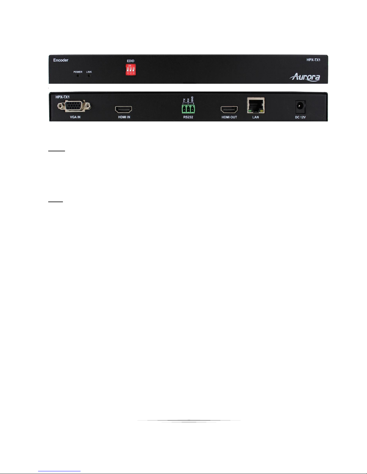
HPX-TX1 Front & Rear
Front
Power LED – LED will light RED when power is applied.
Rear
DC 12V – Connection to 12v / 2A power supply
LAN – 10/100Mbps
HDMI In – HDMI input signal to be encoded and transmitted.
HDMI Out – HDMI Local Loop Out
RS-232 – Serial port control
5
Page 10
User Guide
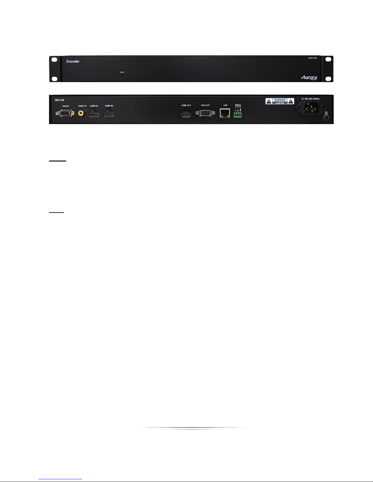
HPX-TX2 Front & Rear
Front
Power LED – LED will light RED when power is applied.
Rear
DC 12V – Connection to 12v / 2A power supply
LAN – 10/100Mbps
HDMI IN1 – HDMI input 1 signal to be encoded and transmitted.
HDMI IN2 – HDMI input 1 signal to be encoded and transmitted.
HDMI Out – HDMI Local Loop Out
VGA Out – VGA Local Loop Out
RS-232 – Serial port control
6
Page 11
User Guide
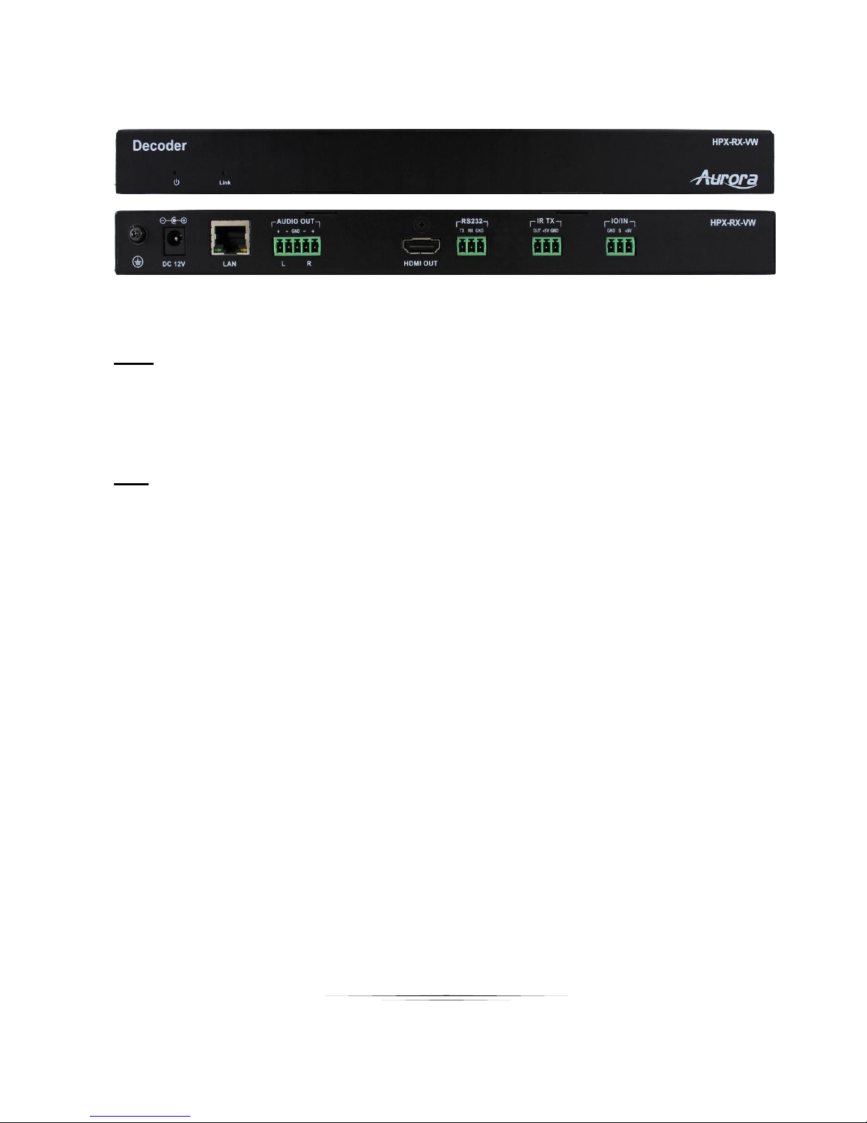
HPX-RX-VW Front & Rear
Front
Power LED – LED will light RED when power is applied.
Rear
GND Symbol – Ground connection
DC 12V – Connection to 12v / 2A power supply
LAN – 10/100Mbps
Audio Out –Audio de-embedded output
HDMI Out – HDMI Output to Display
RS-232 – Serial port control
IR TX – IR Emitter
I/O IN – Digital Input
7
Page 12
User Guide
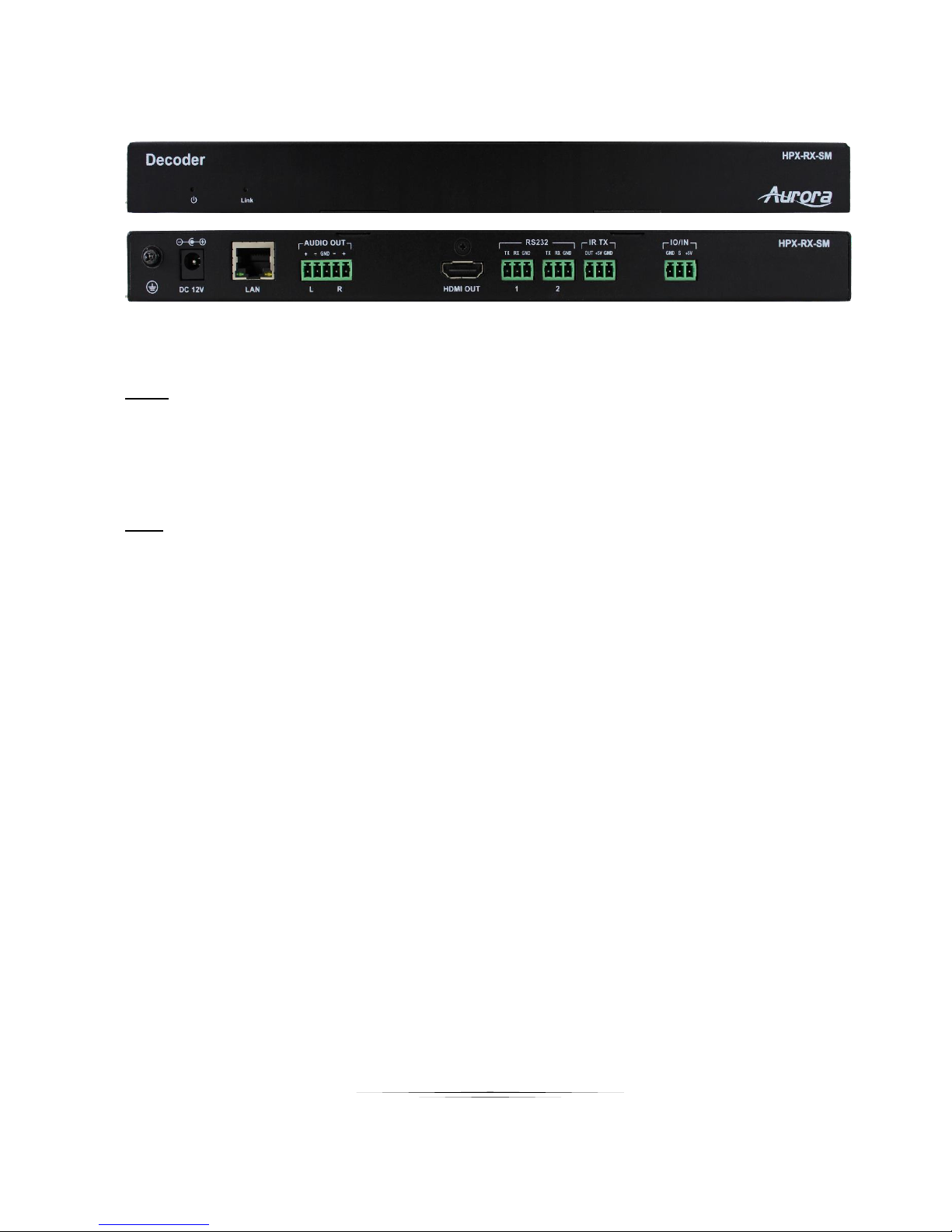
HPX-RX-SM Front & Rear
Front
Power LED – LED will light RED when power is applied.
Rear
GND Symbol – Ground connection
DC 12V – Connection to 12v / 2A power supply
LAN – 10/100Mbps
Audio Out –Audio de-embedded output
HDMI Out – HDMI Output to Display
RS-232 – Serial port control
IR TX – IR Emitter
I/O IN – Digital Input
8
Page 13
User Guide
APPLICATIONS
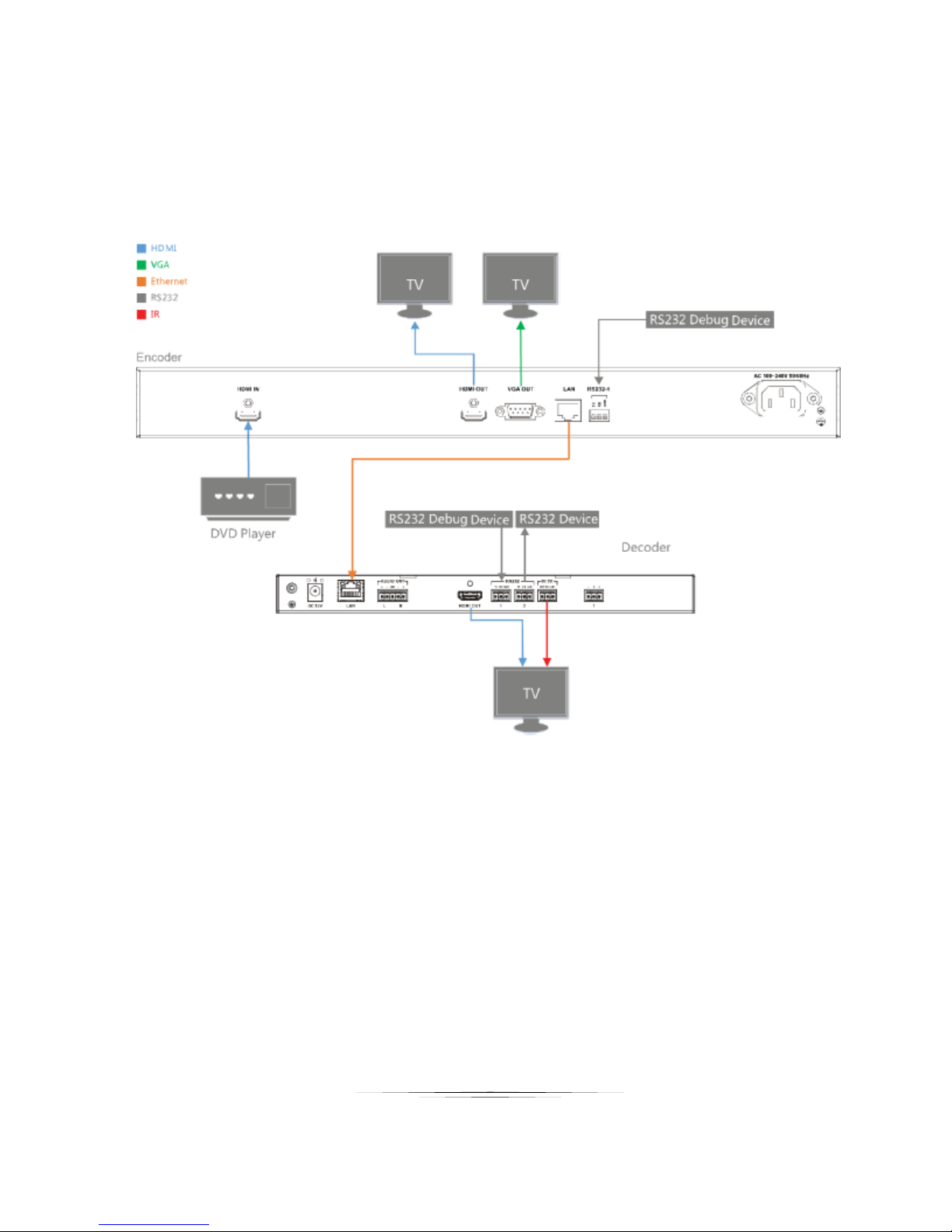
Example 1 HPX-TX1 Transmitter to HPX-RX-SM / VW Receiver
9
Page 14
User Guide
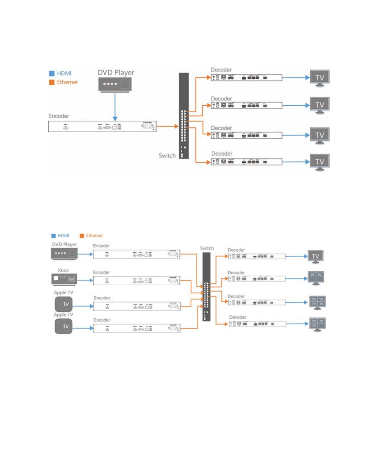
Example 2 HPX-TX1 Transmitter to Multiple HPX-RX-SM / VW Receivers
Example 3 Multiple HPX-TX1 to Multiple HPX-RX-SM / VW
10
Page 15
User Guide
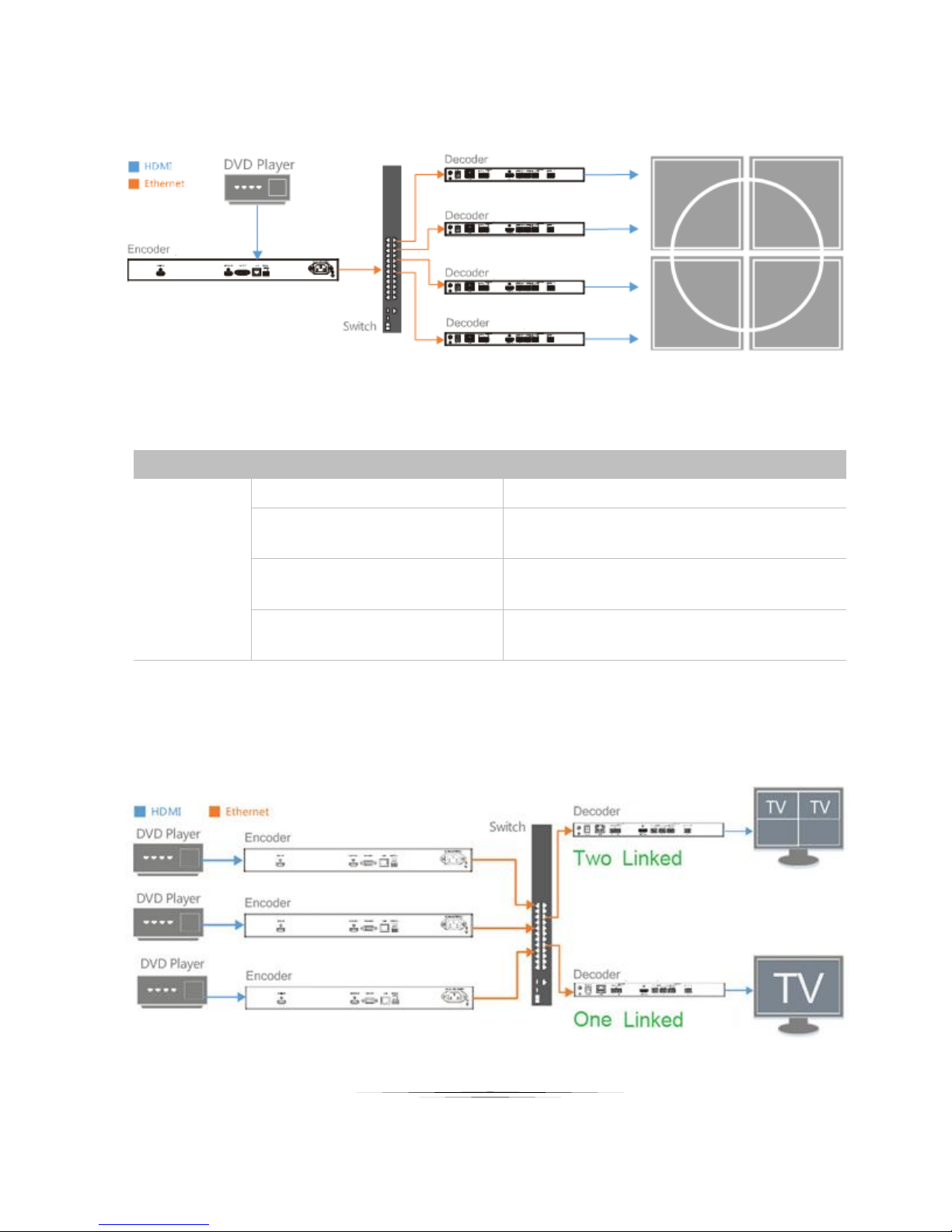
Example 4 Video Wall HPX-RX-VW
Decoder
Number of HPX-RX-VW linked
Viewing effects on the screen
HPX-RX-VW
1
1 complete picture filling the entire screen.
2-4
4 complete pictures filling the entire screen
5-9
9 complete pictures filling the entire screen.
10-16
16 complete pictures filling the entire screen.
Based on the number of IP streams from the sources, a single screen can be divided into 1, 4, 9 or 16 parts
with each part displays a complete picture.
For details, see the following table.
Note:
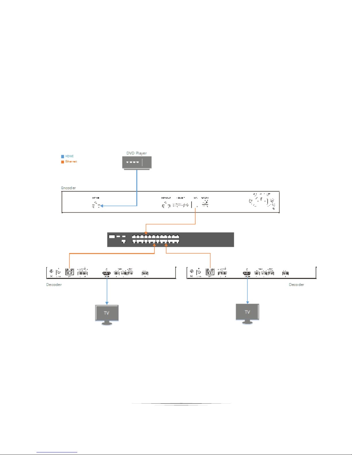
When the number of HPX-RX-SM linked to HPX-TX1/TX2 is from 2-3, 5-8, or 10-15, the unoccupied parts
of the screen show no picture. For example, HPX-TX1 below is linked to one or two HPX-RX-SM, the
displays connected to HPX-RX-SM show one or two complete pictures.
11
Page 16
User Guide
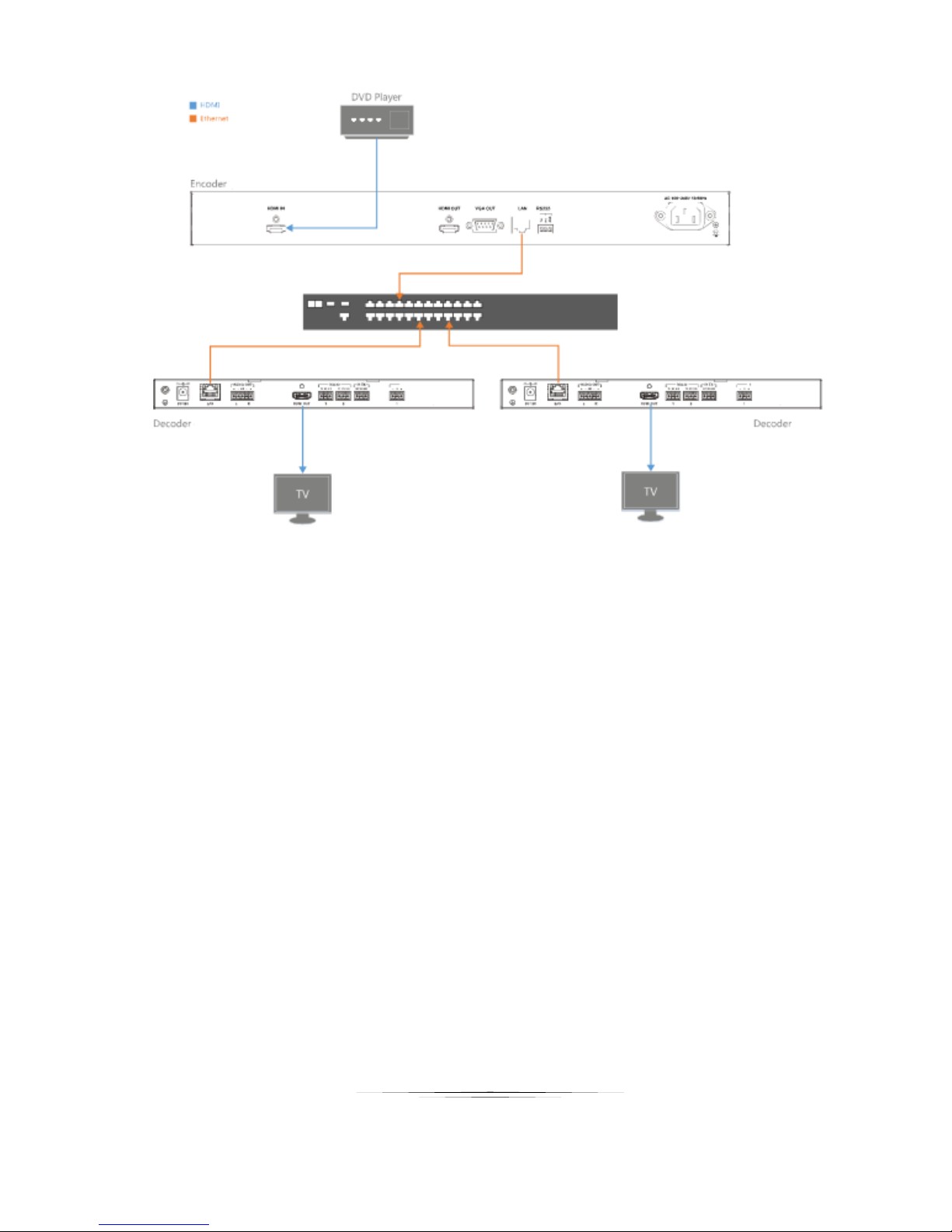
HARDWARE INSTALLATION
1. Connect a HDMI source to the HPX-TX1 / TX2 via a HDMI cable.
2. Connect a HDMI sink to the HPX-RX-SM via a HDMI cable.
3. Connect a HDMI sink to the HPX-RX-VW via a HDMI cable.
4. Connect a computer, HPX-TX1 / TX2, HPX-RX-SM, & HPX-RX-VW to a 10/100Base-T Ethernet switch via
CAT5e/6 cables.
5. Connect the devices to the power supplies and start the operations.
Note:
If the switch doesn’t support PoE function or is unable to provide enough power, connect HPX devices
to the power supplies with their power adapters.
12
Page 17
User Guide
13
Page 18
User Guide
OPERATION
PC Control Tool
Installation
1. Obtain the installation package of the HDMI over IP configuration tool HJ Control V2.4.14.zip.
Double-click HJ Control.exe to start the tool.
Note: The Operation System must be Windows XP or a later version.
You can control the device through the web management page of IP control box as well. For details, please
refer to the User Manual of IP control box
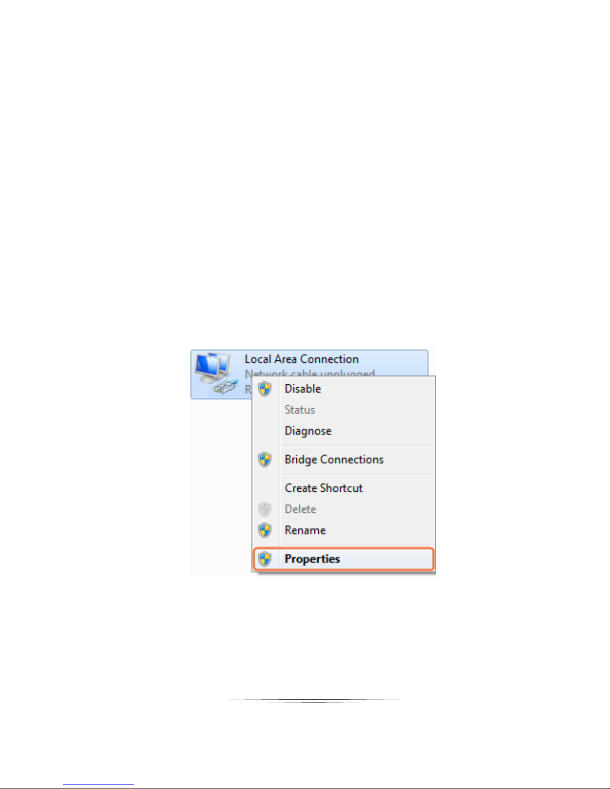
2. Set a static IP on the computer, here take Window 7 as an example.
Step 1. Click Start menu, go to Control Panel > Network and Sharing center > Change Adapter
Settings > Local Area Connection, right click it, choose Properties.
14
Page 19
User Guide
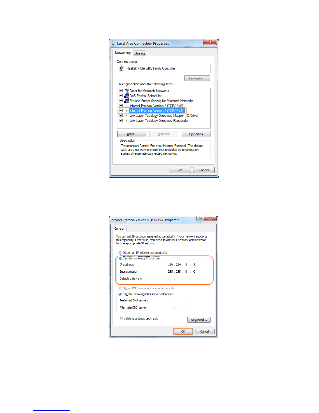
Step 2. Highlight Internet Protocol Version 4 (TCP/IPv4), click Properties.
Step 3. Check Use the following IP address, the IP address enter 169.254.x.x (here take 169.254.2.5
as an example), the subnet mask enter 255.255.0.0. Click OK, then click OK again.
15
Page 20
User Guide
Control Software Instructions
Searching Devices
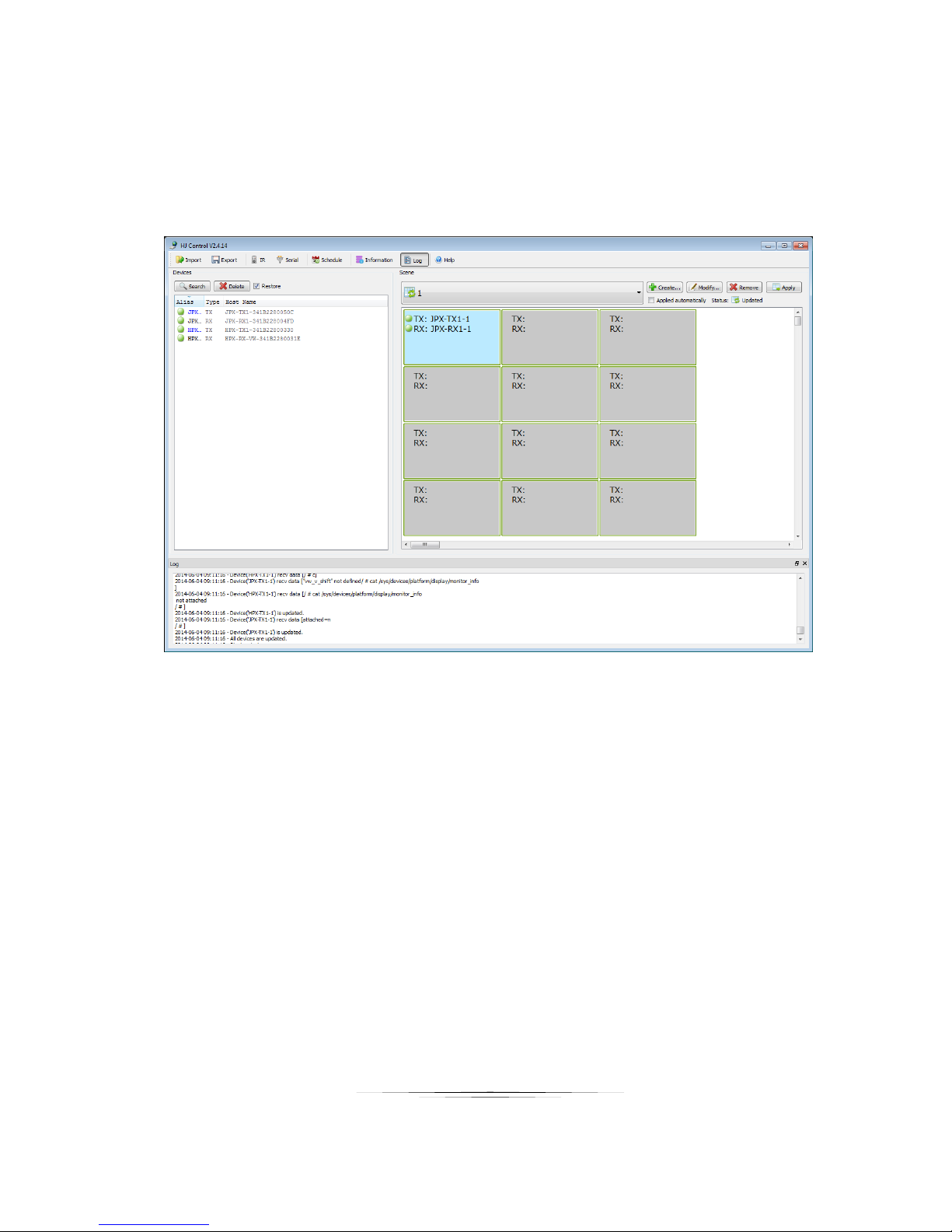
Click Search in the Device list area. The search is started. When completed it will list the devices found on
the network and the “Restore” (previous scene) will be checked by default.
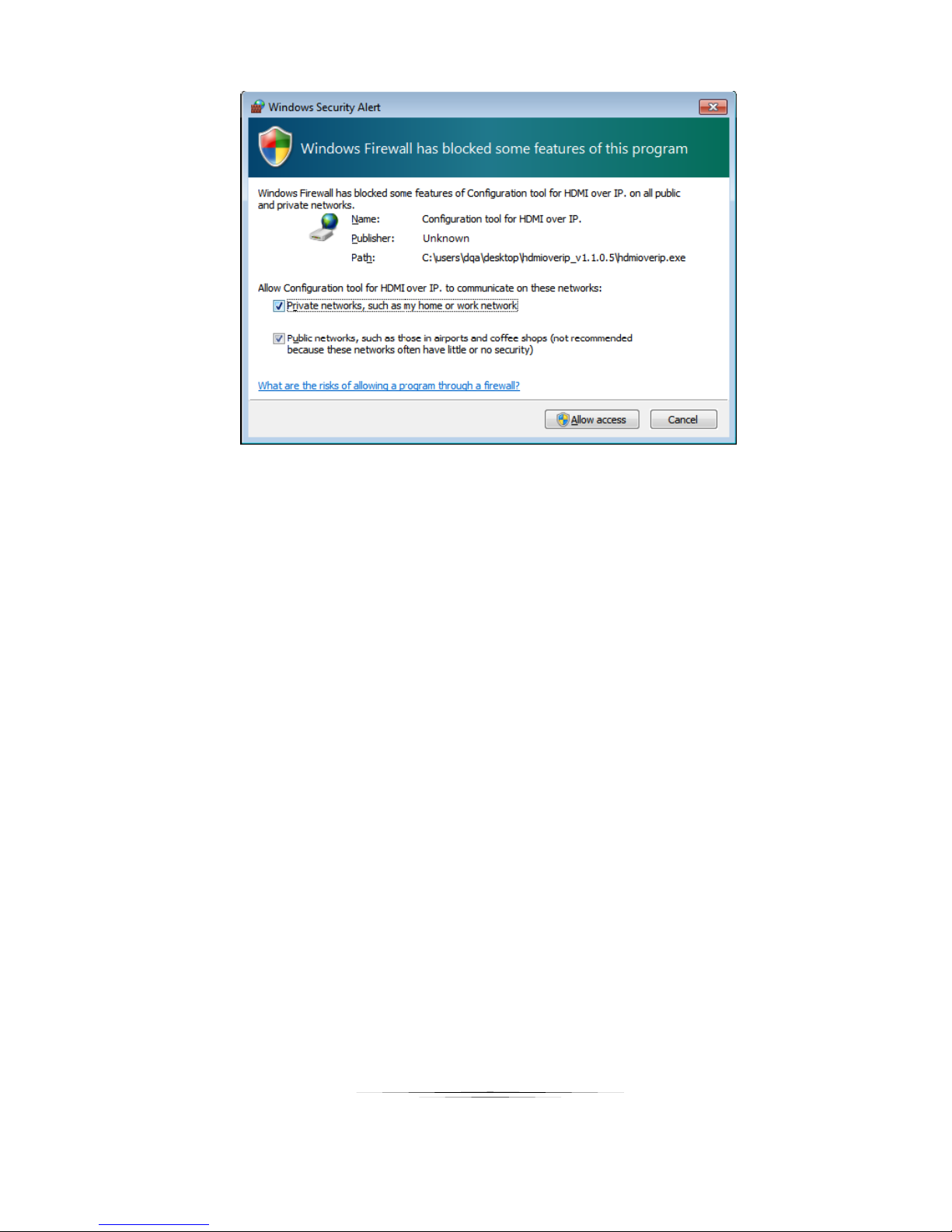
Note: If the Windows Security Alert dialog box comes up, check both boxes and click Allow
access (with Administration Authority)
16
Page 21
User Guide
If no device is found, please refer to problem 1 in Error! Reference source not found..
17
Page 22
User Guide
Setting Device Parameters
Item
Description
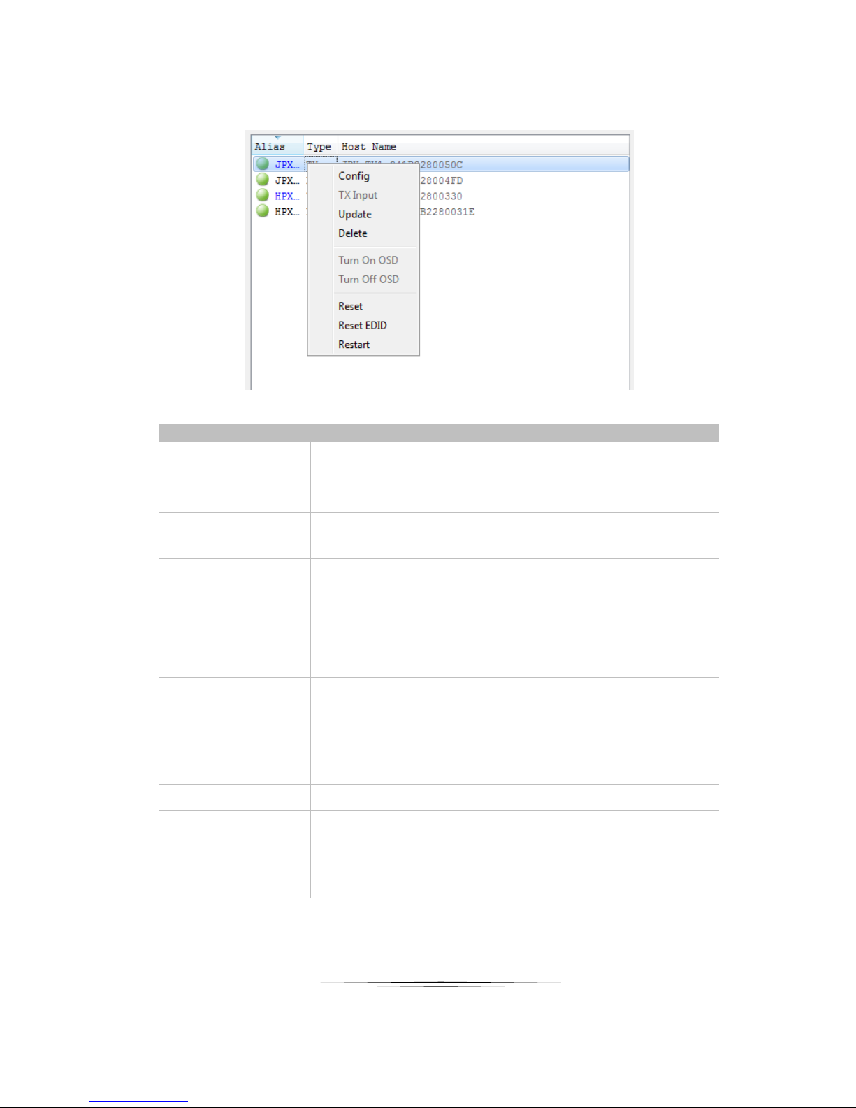
Config
Configure the device parameters, such as device name, alias, IP
address settings (Auto, DHCP, Static).
TX input
Not supported.
Update
Update a single or more device status, such as alias, type or
hostname.
Delete
Delete a single or more devices that have been searched and listed
below in the Devices list.
To display the devices that you have deleted, click Search.
Turn On OSD
Not supported.
Turn Off OSD
Not supported.
Reset
Restore a single or more devices to their factory settings.
This operation may take a few seconds. When reset is completed, the
devices will become active again. It’s recommended that you click
Delete to remove the original devices and click Search to display
them again.
Reset EDID
Not supported.
Restart
Restart a single or more devices that have been searched and listed
below in the Devices list.
This operation may take a few seconds. When restart is completed,
the devices will become active again.
Right click a device in Devices, all the authorized operations are displayed in the shortcut menu.
18
Page 23
User Guide
Device Settings
GUI
Element
Attribute
Description
Devices
Device
parameters
Indicates the current device on which you perform operations.
Host Name
ID
Indicates the host name ID, which is generated by the system and cannot be
changed.
Alias
Indicates the user-defined device name that contains a maximum of 80
characters.
Auto
IP
distribution
modes
Indicates a mode in which the device is assigned an IP address automatically.
DHCP
Indicates a mode in which the device is assigned an IP address by using a
router or switch with a DHCP server.
Static
Indicates a mode in which the device is assigned an IP address manually. In
this case, enter an IP address (169.254.x.x) in IP Address and 255.255.0.0 in
Subnet Mask.
IP Address
Network
parameters
Indicates the device IP address, which can be set only when the static mode is
selected.
Subnet
Mask
Indicates the device subnet mask, which can be set only when the static mode
is selected.
OK
Buttons
Saves current settings, applies them to the device, and closes this dialog box.
Cancel
Cancels current settings and closes this dialog box.
Apply
Saves current settings and applies them to the device without closing this
dialog box.
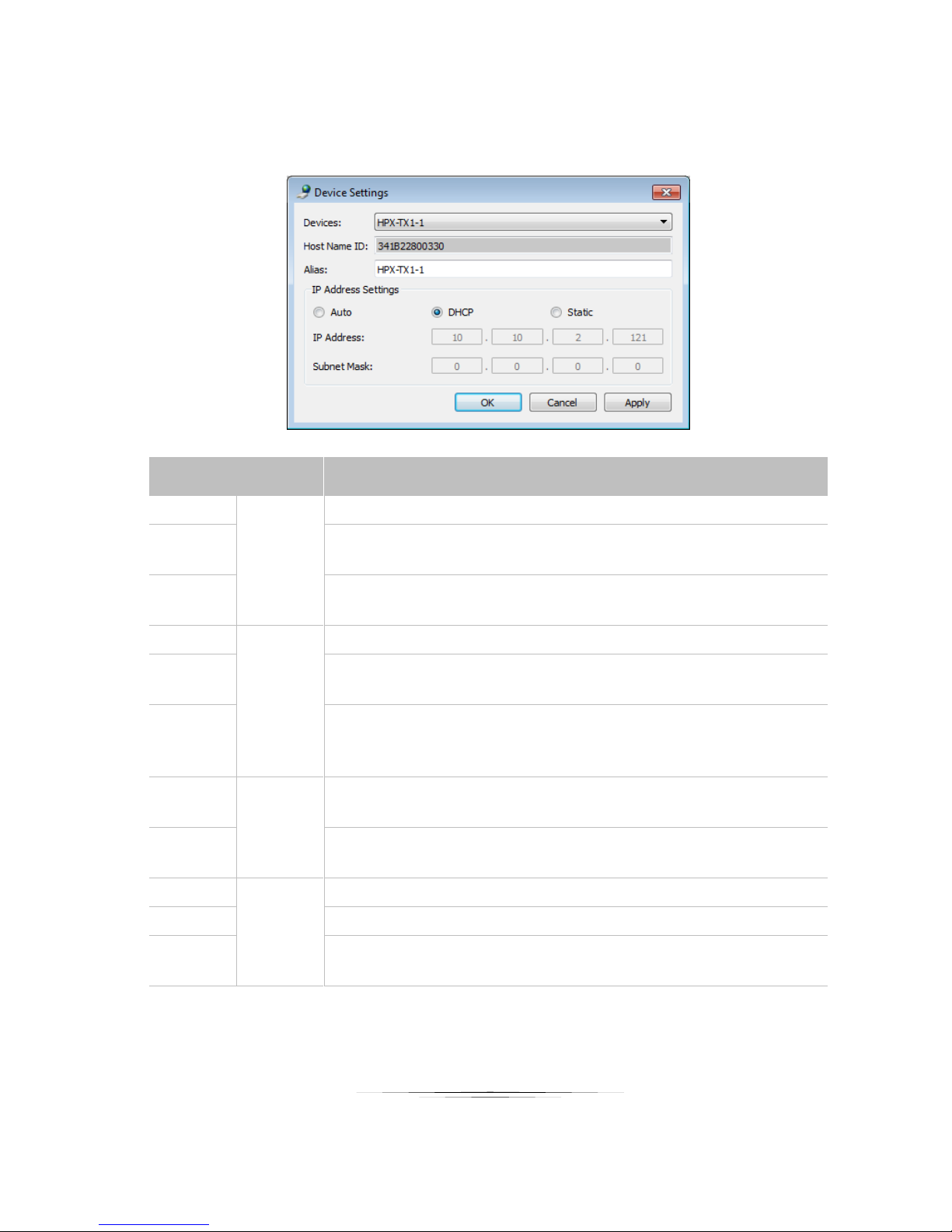
In the Devices list, right-click on any device, and then choose Config to display Device Settings window. Or you can
also double-click on any device to display this window.
Note:
If any changes are made to the IP distribution modes, for example it is changed from Static to Auto or
DHCP, restart the device and search it again in the control software.
19
Page 24
User Guide
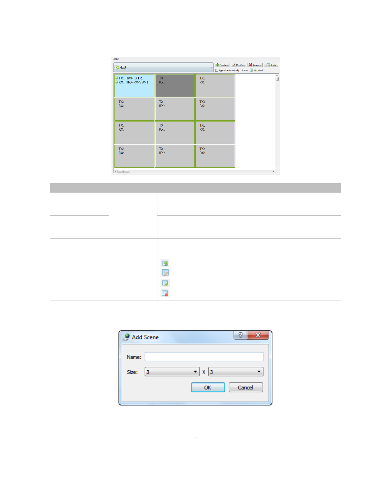
Matrix Setting Introduction
GUI Element
Attribute
Description
Create
Buttons
Creates a new configuration scene.
Modify
Modifies the current configuration scene.
Remove
Deletes the current configuration scene.
Apply
Applies the configuration connection settings to the connected devices.
Applied
automatically
Option
Indicates that settings are applied immediately after you configure the
intersection between TX and RX.
Status
Icons
Indicates that the matrix created by devices is restored.
Indicates that matrix settings are in progress.
Indicates that matrix settings are applied successfully.
Indicates that matrix settings fail to be applied.
On the home screen of the control software, the Scene area displays the status of all TX and RX connections.
Creating the Scene Window
6. Click Create in the Scene area, the Add Scene dialog box is displayed.
7. Change the configuration layout, for example set Name to 3 x 3 and Size to 3 x 3.
20
Page 25
User Guide
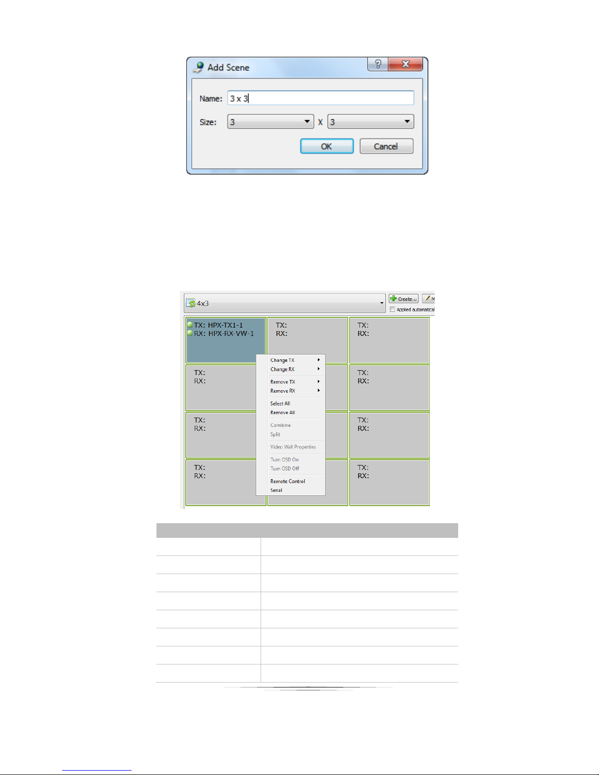
GUI Element
Description
Change TX
Selects TX from the searched devices.
Change RX
Selects RX from the searched devices.
Remove TX
Deletes the TX from the searched devices.
Remove RX
Deletes the RX from the search devices.
Select All
Selects all the cells in the Scene area.
Remove All
Remove all the devices in the Scene area.
Combine
Not supported.
Split
Not supported.
8. Click OK.
Note:
To modify the current configuration layout, click Modify on the tool bar.
Scene Area Window Instruction
You can right click a cell in the Scene area to perform the operations from the shortcut menu.
21
Page 26

User Guide
GUI Element
Description
Video Wall Properties
Not supported.
Turn OSD On
Not supported.
Turn OSD Off
Not supported.
Remote control
IR remote to send IR commands to control the
source or device from your computer.
Serial
Sends commands to a RS232 device
connected to HPX-TX1/TX2 or HPX-RXVW/SM for device configuration and control.
Note:
You can also click and drag the desired TX and RX from the Devices list to cells in the Scene area and
apply the configuration connection settings.
22
Page 27
User Guide
Setting a Matrix
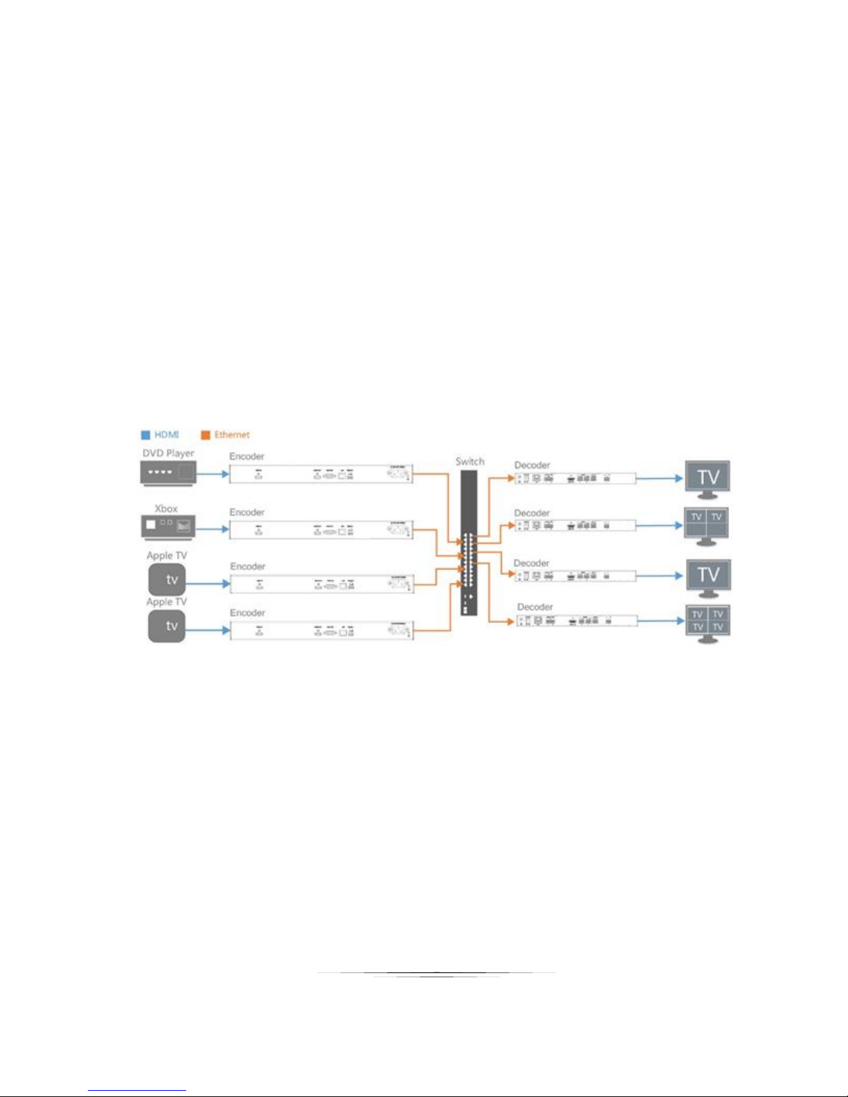
You can set a matrix through the control software to control and manage all the connected devices in a network. This
section takes a 2 x 2 matrix as an example.
Preparations:
Four encoder HPX-TX1/TX2s
Two decoder HPX-RX-VWs
Two decoder HPX-RX-SMs
One 10/100Base-T Ethernet switch.
Four HDMI source devices
Four display devices
A computer
Eight HDMI cables and eight CAT5e/6 cables
Hardware Connection:
23
Page 28
User Guide
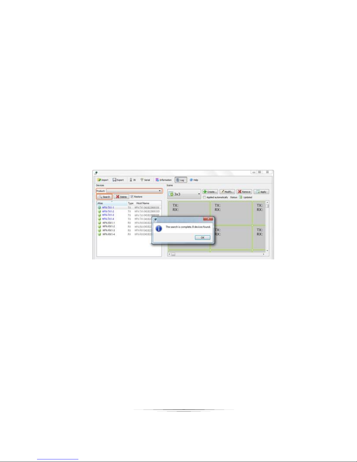
9. Connect one DVD player, one Xbox, two Apple TVs to four HPX-TX1/TX2 via four HDMI cables.
10. Connect the HPX-TX/TX2s to the 10/100Base-T Ethernet switch with four CAT5e/6 cables.
11. Connect four TVs to two HPX-RX-VWs and two HPX-RX-SMs via four HDMI cables.
12. Connect the HPX-RX-VWs and HPX-RX-SMs to the switch with four CAT5/6 cables.
13. Connect your computer to the switch with a CAT5e/6 cable.
14. Power on all the devices.
Note:
If the switch doesn’t support PoE function, connect the HPX-RX-VWs and HPX-RX-SMs to the power
supplies.
Operation:
15. Double-click HJ Control.exe to launch the control software; Select HPX-TX1/TX2 or HPXRX-VW/SM from Product list; Click Search as shown below to start searching TX/RX, and
eight devices are found.
24
Page 29
User Guide
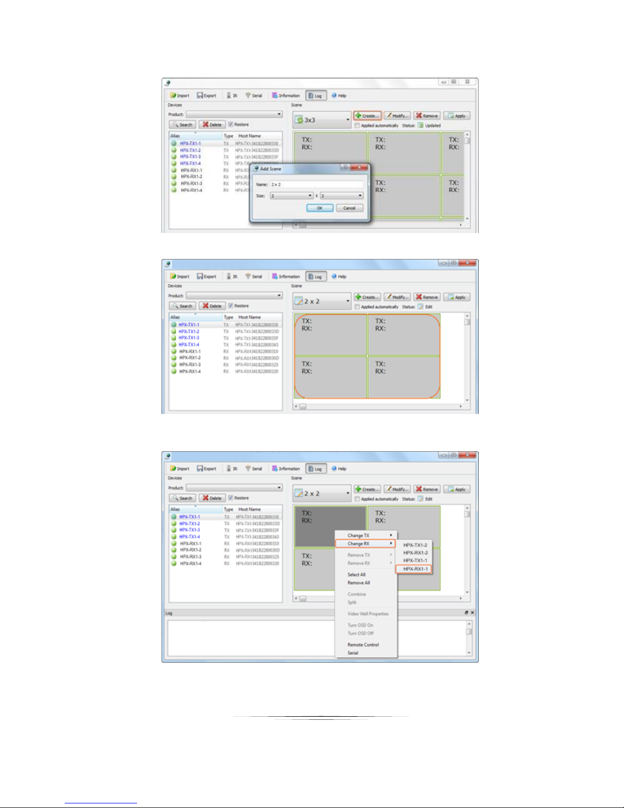
16. Click Create to create a 2 x 2 configuration scene.
17. Click OK, 2 x 2 configuration scene is created as shown below.
18. Configure the intersection between TX and RX in different cells in the Scene area.
1) Right click the first cell, choose Change RX and then HPX-RX1-1.
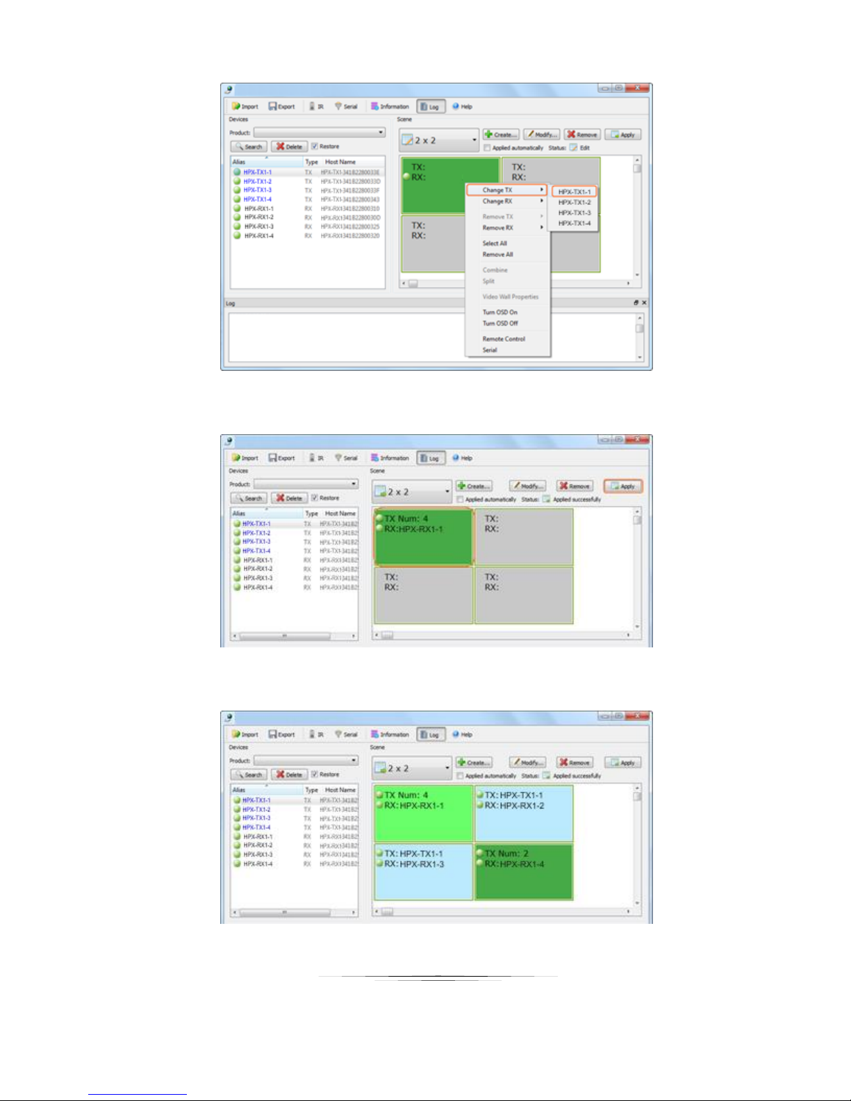
2) Right click the first cell, choose Change TX and then HPX-TX1.
25
Page 30
User Guide
3) Repeat the above steps to select HPX-TX2 or HPX-RX-VW/SM to configure the intersection between
TX and RX in the first cell. And click Apply to make the changes to TX and RX take effective.
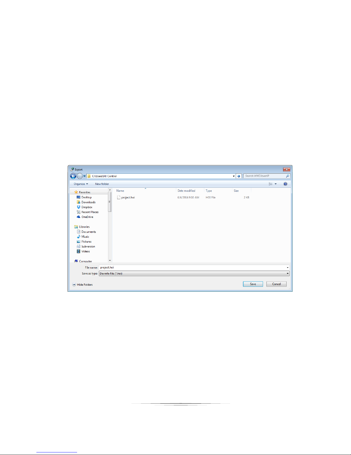
4) Configure the intersection between TX and RX in other cells in the same way as above. The final scene
is created as below.
Then you can see the displays connected to HPX-RX-VWs show a complete picture filling the screen, the displays
26
Page 31
User Guide
connected to HPX-RX-SMs show multiple complete pictures with the unoccupied parts shows nothing.
Note:
If HPX-RX-SM is linked to a single HPX-TX1/TX2, the display will show a complete picture filling the
screen as that connected to HPX-RX-VW.
After 2 x 2 matrix is created, you can change TX and RX using the control software to enjoy different
viewing effects.
Configuration Files Management
When the control software is closed, the Windows operating system would save the configuration file project.hoi to
the working directory of current user.
Viewing the Default Configuration File Directory
You can view the default directory from the Import dialog box displayed by clicking Import on the tool bar.
When running the control software next time, it would automatically read the configuration file default.hoi. Do not
modify or delete the default.hoi.
Otherwise, errors may be encountered during program running.
Export or Import the Configuration File
On the home screen of the control software, you can:
Click Export on the tool bar to save the current devices and scene configuration file to a specified directory.
Click Import on the tool bar to import the saved configuration file from this directory.
27
Page 32
User Guide
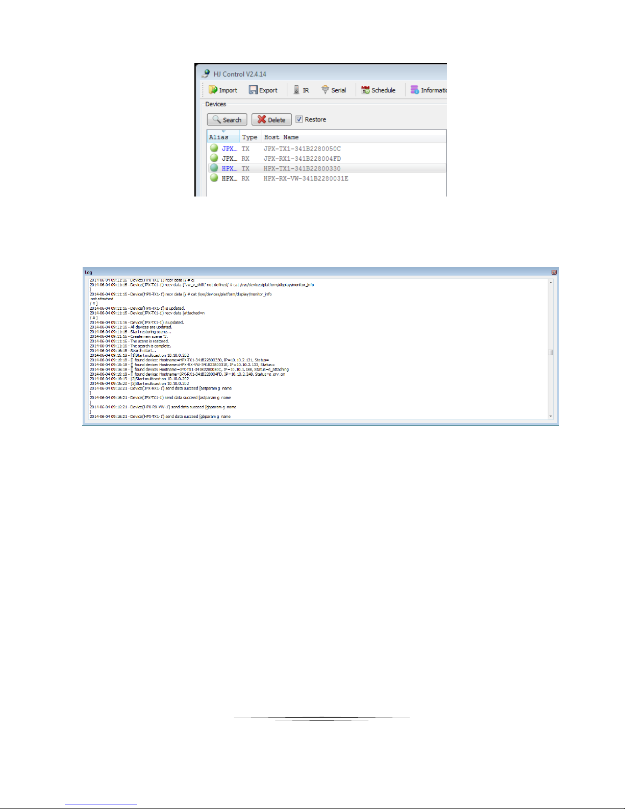
Logs
The logs have recorded the software operation and device communication information, which can be used for
troubleshooting.
28
Page 33
User Guide
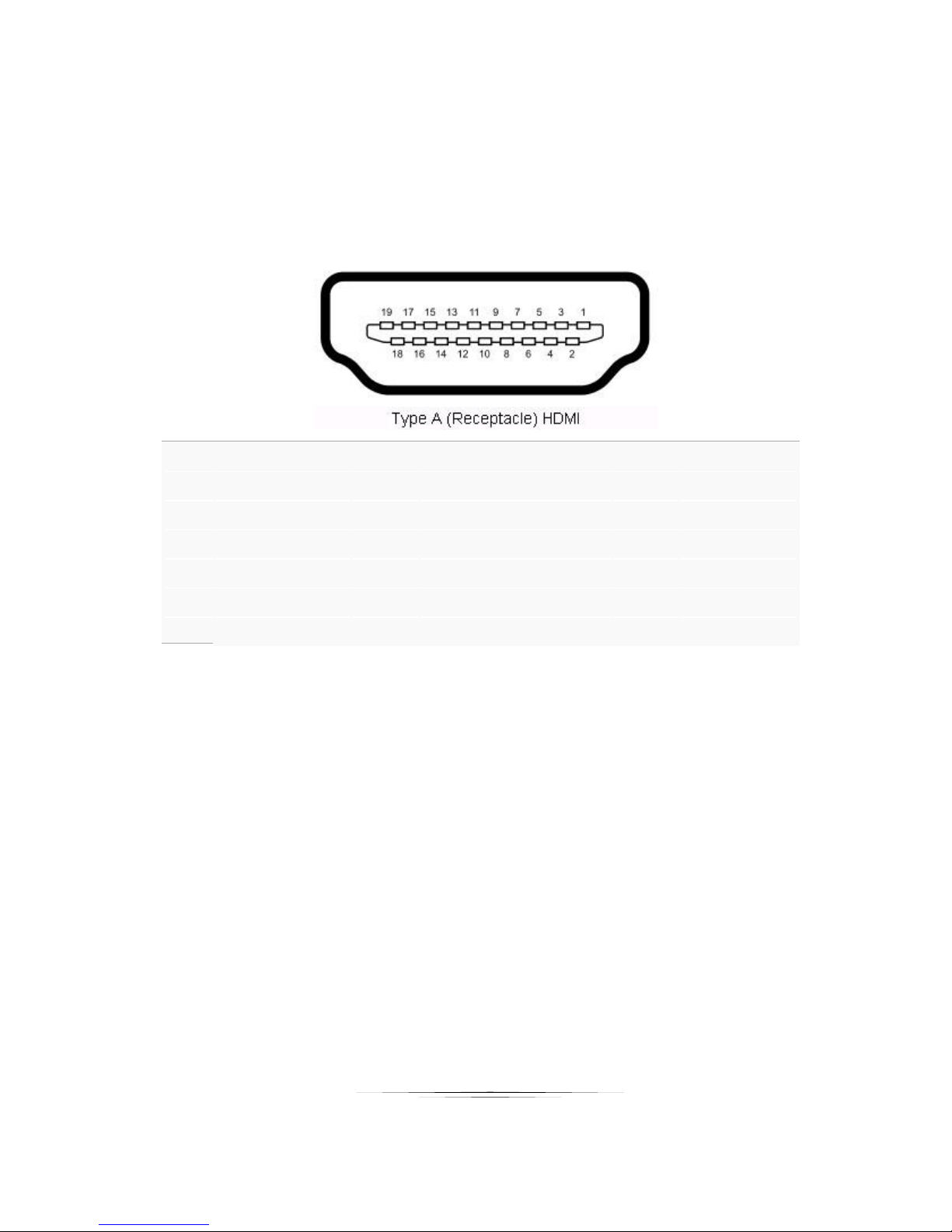
CONNECTOR PIN DEFINITION
Pin 1 TMDS
Data2+
Pin
8
TMDS Data0 Sh
ield
Pin
15
SCL
Pin 2 TMDS Data2 Sh
ield
Pin
9
TMDS
Data0–
Pin
16
SDA Pin 3 TMDS
Data2–
Pin
10
TMDS
Clock+
Pin
17
DDC/CEC Gr
ound
Pin 4 TMDS
Data1+
Pin
11
TMDS Clock Sh
ield
Pin
18
+5 V Powe
r
Pin 5 TMDS Data1 Sh
ield
Pin
12
TMDS
Clock–
Pin
19
Hot Plug
Detect
Pin 6 TMDS
Data1–
Pin
13
CEC
Pin 7 TMDS
Data0+
Pin
14
Reserved (N.C. on
device)
HDMI
29
Page 34
User Guide
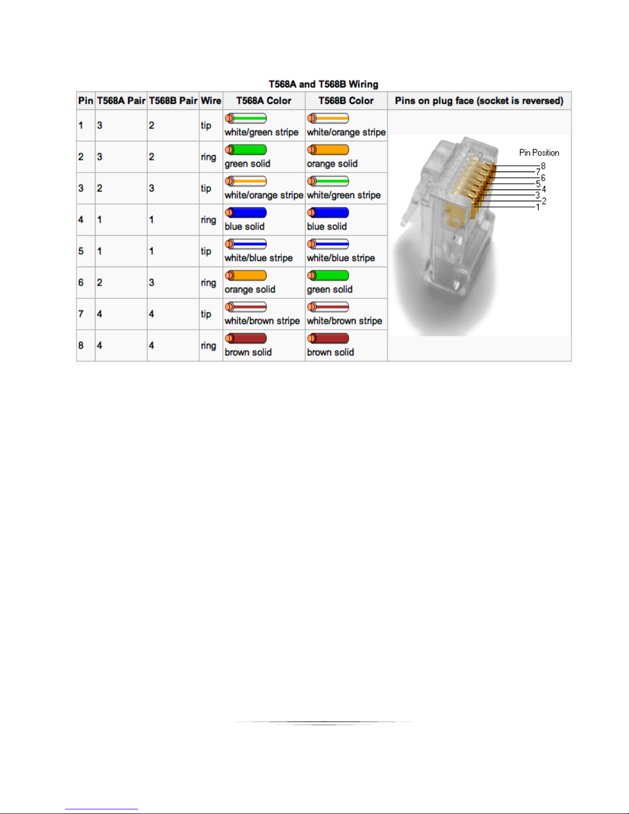
CAT5e/6/6A
1. All transmission distances are measured using Belden 1583A CAT5e 125MHz Solid UTP cable. The transmission distance is
defined as the distance between the video source and the display.
2. To reduce the interference among the unshielded twisted pairs of wires in UTP cable, you can use shielded STP cables to
improve EMI problems, which is worsen in long transmission.
30
Page 35
User Guide
APPENDIX 1 Troubleshooting
Why HDMI over IP console cannot find any devices?
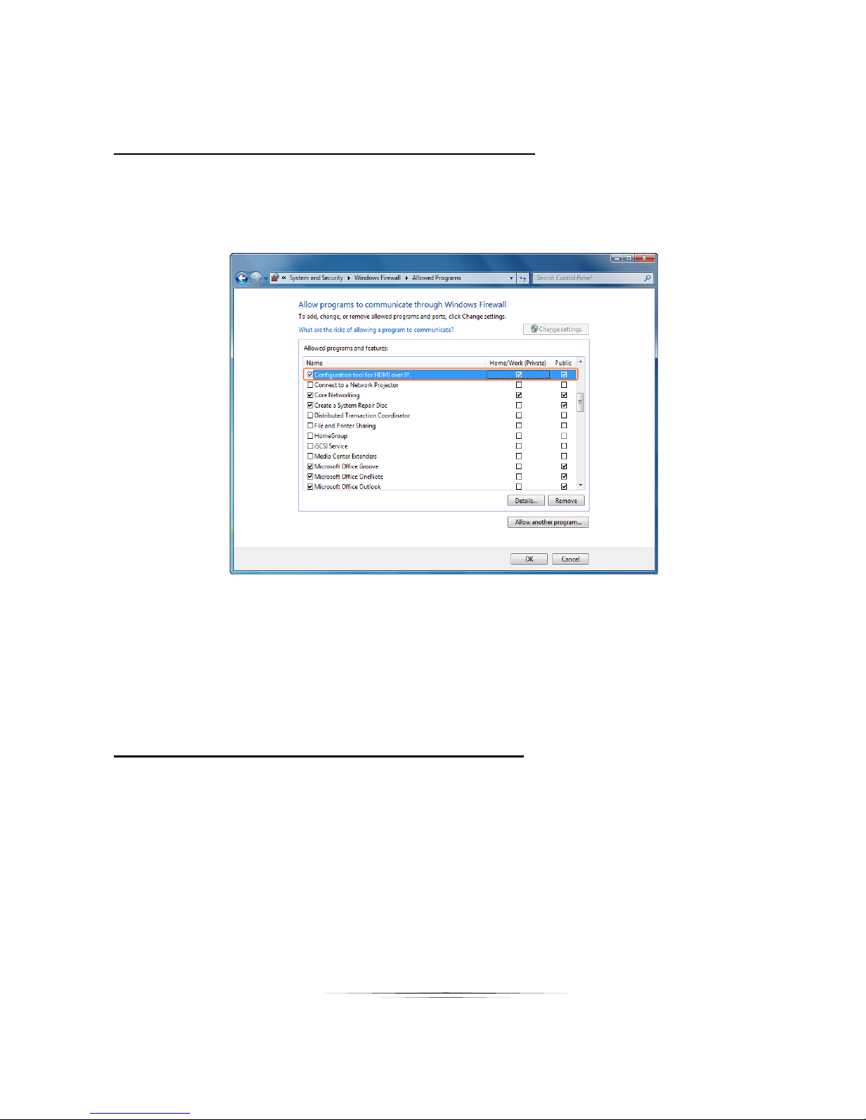
1) Check Windows Firewall. Take Windows 7 as an example: Click Start menu, go to Control Panel >
System and Security > Windows Firewall > Allowed Programs, highlight Configuration tool for
HDMI over IP, check Home/Work (Private) and Public.
2) Check the IP address and subnet mask of the PC. The network segment for IP address is 169.254.x.x
and the subnet mask is 255.255.0.0, the PC and Transmitter/Receiver should be in the same network
segment. For details, please refer to PC control tool in chapter Operation.
3) Check the IGMP Snooping status in Switch. This function should be enabled.
Why display shows no picture with RX connected?
Check the following items:
All devices are powered on.
A picture is achieved when connecting the source directly to the TV.
TV has switched to the right signal source input mode using your TV remote, such as switching to HDMI
1 if HDMI 1 interface is connected to the RX via a HDMI cable.
All the cables are qualified.
The Switch supports IGMP snooping and this function is enabled.
31
Page 36

User Guide
APPENDIX 2 Firmware Update
For the latest firmware updates please go www.auroramm.com
You must be signed up to the Customer Portal in order to download firmware with
instructions on how to update.
32
Page 37
User Guide
APPENDIX 3 Technical Specifications
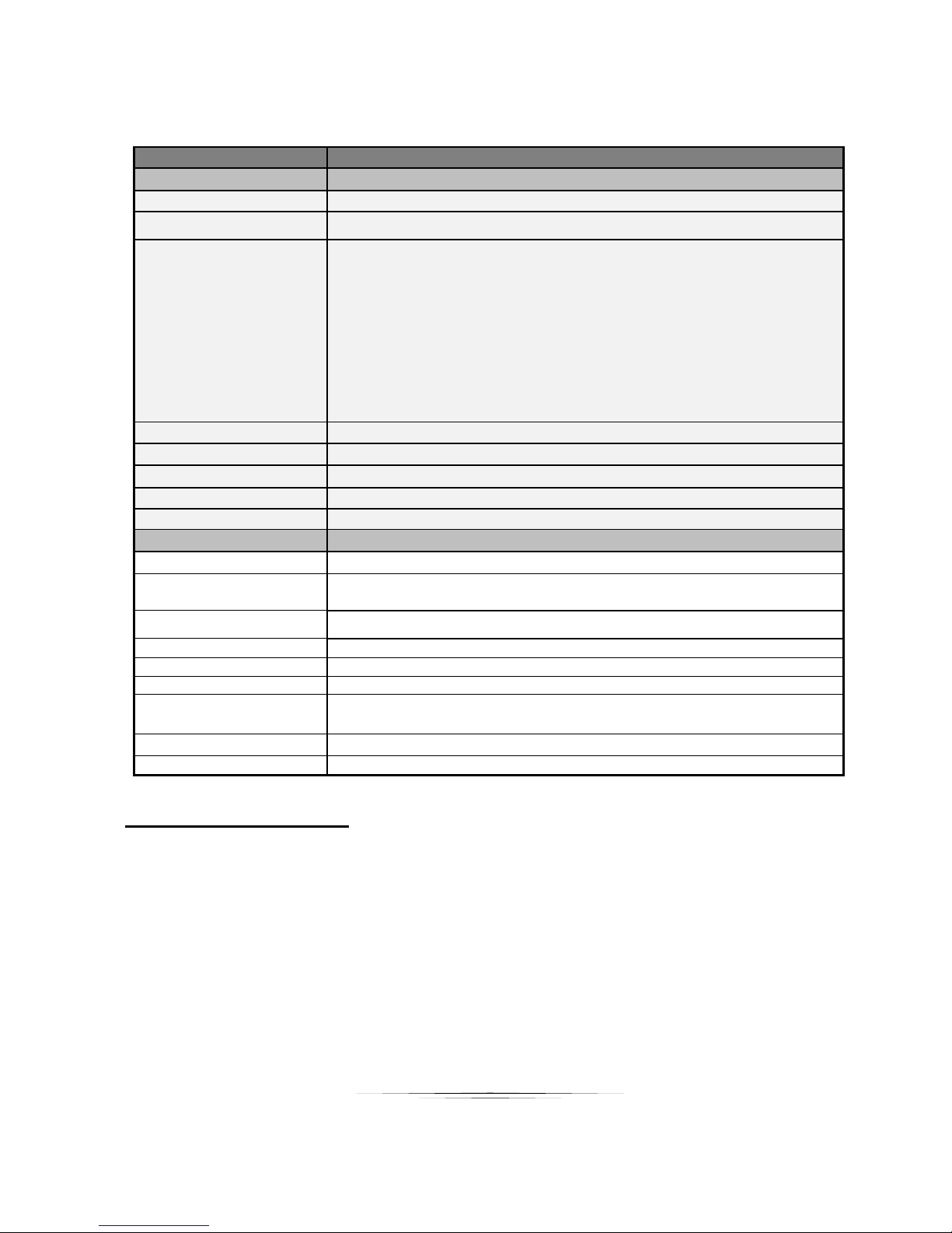
Model Name
HPX-TX1
Technical
HPX-TX1
Data Rate
1K – 40Mbps Configurable
Distance
330ft / 100m Max
I/O Connections
Transmitter
1 x RJ45 port,
1 x HDMI IN,
1 x VGA IN,
1 x HDMI OUT,
1 x RS232 (3.5 mm phoenix)
Input Video Signal
1.2 volts p-p
Input DDC Signal
5 volts p-p (TTL)
Supported Video Formats
1080P / 1080i / 720P / 576P / 480P/ 576i / 480i
Output Video
HDMI
Latency
120ms – 150ms
Mechanical
HPX Series
Housing
Black Painted Steel
Dimensions
[L x W x H]
9.96" x 6.11" x .984 (253mm X 155.2mm X 25mm)
Weight
4lbs (1.81kg)
Mounting
Ear Tabs
Power supply
12V DC
Power consumption
6.3W
Operation temperature
0~35C [32~95F]
Storage temperature
-20~70C [-4~140F]
Relative humidity
10~90% RH [no condensation]
Specifications subject to change without notice.
33
Page 38
User Guide
Model Name
HPX-TX2
Technical
HPX-TX2
Data Rate
1K – 40Mbps Configurable
Distance
330ft / 100m Max
I/O Connections
Transmitter
1 x RJ45 port,
2 x HDMI IN,
1 x VGA IN,
1 x VIDEO IN,
1 x HDMI OUT,
1 x VGA OUT,
1 x RS232 (3.5 mm phoenix)
Input Video Signal
1.2 volts p-p
Input DDC Signal
5 volts p-p (TTL)
Supported Video Formats
1080P / 1080i / 720P / 576P / 480P/ 576i / 480i
Output Video
HDMI + HDCP
Output Audio
Analog Stereo
Mechanical
HPX Series
Housing
Black Painted Steel
Dimensions
[L x W x H]
17.3’’ × 8.3’’ × 1.7’’ (440mm × 122mm × 44mm)
Weight
4.85lbs (2.2Kg)
Mounting
Ear Tabs
Power supply
AC 100-240V 50/60Hz
Power consumption
5W
Operation temperature
0~35C [32~95F]
Storage temperature
-20~70C [-4~140F]
Relative humidity
10~90% RH [no condensation]
Specifications subject to change without notice.
34
Page 39
User Guide
Model Name
HPX-RX-VW / SM
Technical
HPX-RX-VW / SM
Data Rate
1K – 40Mbps Configurable
Distance
330ft / 100m Max
I/O Connections
Receiver
4 x USB (A type),
1 x RJ45 port,
1 x HDMI OUT,
1 x RS232,
1 x AUDIO OUT,
1 x IR OUT
Input Video Signal
1.2 volts p-p
Input DDC Signal
5 volts p-p (TTL)
Supported Video Formats
1080P / 1080i / 720P / 576P / 480P/ 576i / 480i
Output Video
HDMI + HDCP
Output Audio
Analog Stereo
Mechanical
HPX Series
Housing
Black Painted Steel
Dimensions
[L x W x H]
15.4’’ × 8.7’’ × 3.6’’ (269mm × 110mm × 24mm)
Weight
1.72lbs (0.78Kg)
Mounting
Ear Tabs
Power supply
12V DC 2A 5.5mm
Power consumption
4.56W
Operation temperature
0~35C [32~95F]
Storage temperature
-20~70C [-4~140F]
Relative humidity
10~90% RH [no condensation]
Specifications subject to change without notice.
35
Page 40

User Guide
APPENDIX 4 Warranty
Limited 3 Year Warranty
Aurora Multimedia Corp. (“Manufacturer”) warrants that this product is free of defects in both materials and
workmanship for a period of 3 years as defined herein for parts and labor from date of purchase. This Limited Warranty
covers products purchased in the year of 2009 and after. Motorized mechanical parts (Hard Drives, DVD, etc),
mechanical parts (buttons, doors, etc), remotes and cables are covered for a period of 1 year. Touch screen displays
are covered for 1 year; touch screen overlay components are covered for 90 days. Supplied batteries are not covered
by this warranty. During the warranty period, and upon proof of purchase, the product will be repaired or replaced (with
same or similar model) at our option without charge for parts or labor for the specified product lifetime warranty period.
This warranty shall not apply if any of the following:
A. The product has been damaged by negligence, accident, lightning, water, act-of-God or mishandling; or,
B. The product has not been operated in accordance with procedures specified in operating instructions: or,
C. The product has been repaired and or altered by other than manufacturer or authorized service center; or,
D. The product's original serial number has been modified or removed: or,
E. External equipment other than supplied by manufacturer, in determination of manufacturer, shall have
affected the performance, safety or reliability of the product.
F. Part(s) are no longer available for product.
In the event that the product needs repair or replacement during the specified warranty period, product should be
shipped back to Manufacturer at Purchaser's expense. Repaired or replaced product shall be returned to Purchaser
by standard shipping methods at Manufacturer's discretion. Express shipping will be at the expense of the Purchaser.
If Purchaser resides outside the contiguous US, return shipping shall be at Purchaser's expense.
No other warranty, express or implied other than Manufacturer's shall apply.
Manufacturer does not assume any responsibility for consequential damages, expenses or loss of revenue or property,
inconvenience or interruption in operation experienced by the customer due to a malfunction of the purchased
equipment. No warranty service performed on any product shall extend the applicable warranty period. This warranty
does not cover damage to the equipment during shipping and Manufacturer assumes no responsibility for such
damage.
36
Page 41

User Guide
This product warranty extends to the original purchaser only and will be null and void upon any assignment or
Aurora Multimedia Corp.
205 Commercial Court
Morganville, NJ 07751
Phone: 732-591-5800 Fax: 732-591-6801
www.auroramm.com
37
 Loading...