

Page 1
Manual Number: 140530
Firmware: v1.21 & above
USERS GUIDE
DXW-2 Series
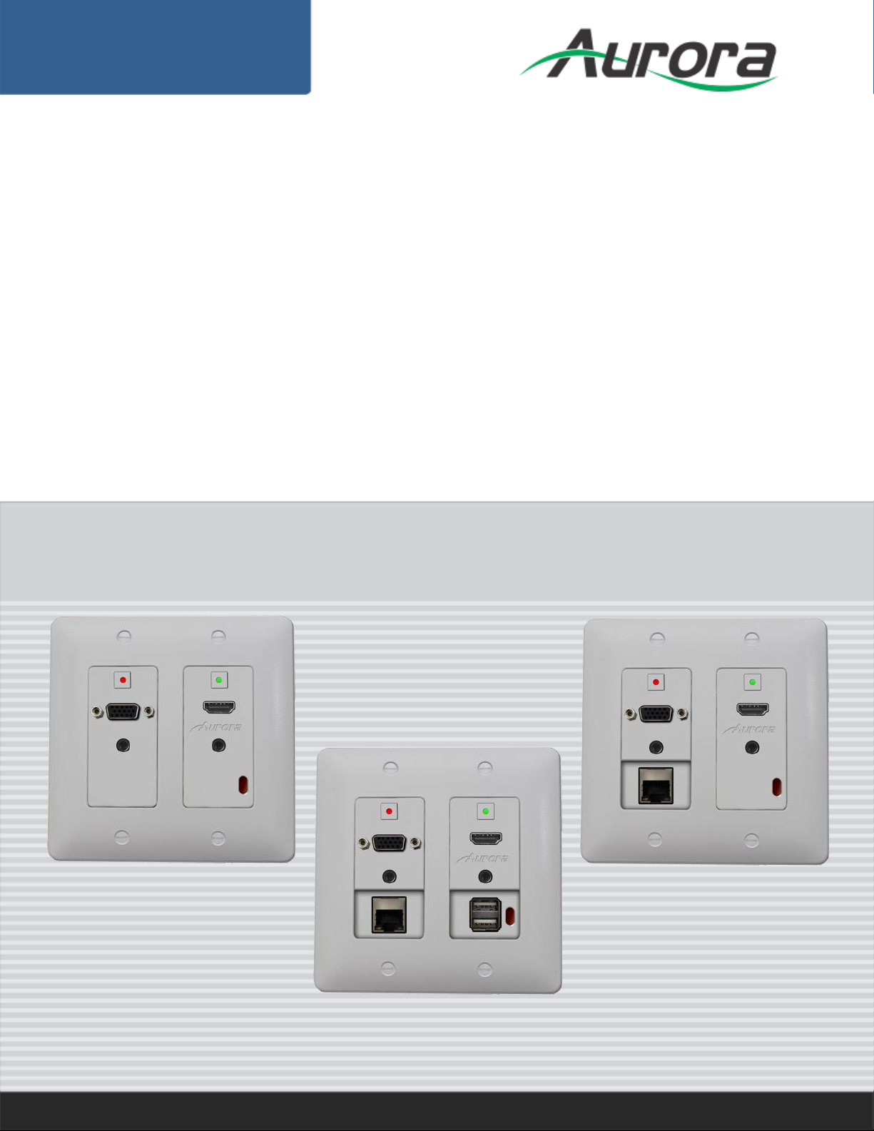
2 Gang Decora® HDBaseT Wall Plate
DXW-2E
DXW-2
DXW-2EU / DXW-2EUH
i
Page 2
User Guide
The lightning symbol in the triangle is used to alert you to the presence of dangerous voltage
inside the product that may be sufficient to constitute a risk of electric shock to anyone opening
the case. It is also used to indicate improper installation or handling of the product that could
damage the electrical system in the product or in other equipment attached to the product.
The exclamation point in the triangle is used to alert you to important operating and maintenance
instructions. Failure to follow these instructions could result in injury to you or damage to the
product.
SAFETY INSTRUCTIONS
Please review the following safety precautions. If this is the first time using this model, then read this manual
before installing or using the product. If the product is not functioning properly, please contact your local
dealer or Aurora for further instructions.
Be careful with electricity:
Power outlet: To prevent electric shock, be sure the electrical plug used on the product power cord
matches the electrical outlet used to supply power to the Aurora product. Use only the power adapter
and power connection cables designed for this unit.
Power cord: Be sure the power cord is routed so that it will not be stepped on or pinched by heavy
items.
Lightning: For protection from lightning or when the product is left unattended for a long period,
disconnect it from the power source.
.
Also follow these precautions:
Ventilation: Do not block the ventilation slots if applicable on the product or place any heavy object on
top of it.
Blocking the air flow could cause damage. Arrange components so that air can flow freely. Ensure that
there is adequate ventilation if the product is placed in a stand or cabinet. Put the product in a properly
ventilated area, away from direct sunlight or any source of heat.
Overheating: Avoid stacking the Aurora product on top of a hot component such as a power amplifier.
Risk of Fire: Do not place unit on top of any easily combustible material, such as carpet or fabric.
Proper Connections: Be sure all cables and equipment are connected to the unit as described in this
manual.
Object Entry: To avoid electric shock, never stick anything in the slots on the case or remove the cover.
Water Exposure: To reduce the risk of fire or electric shock, do not expose to rain or moisture.
Cleaning: Do not use liquid or aerosol cleaners to clean this unit. Always unplug the power to the
device before cleaning.
ESD: Handle this unit with proper ESD care. Failure to do so can result in failure.
FCC
This device complies with Part 15 of the FCC Rules. Operation is subject to the following two conditions:
(1) This device may not cause harmful interference.
(2) This device must accept any interference received, including interference that may cause undesired
operation.
Trademarks
All trademarks in this document are the properties of their respective owners.
i
Page 3

User Guide
TABLE OF CONTENTS
PACKAGE CONTENTS ................................ ............................................................................. 1
INTRODUCTION ........................................................................................................................ 2
About ..................................................................................................................................................... 2
Features ................................................................................................................................................ 2
Front DXW-2, DXW-2E, DXW-2EU, DXW-2EUH ................................................................................. 3
Rear Panel DXW-2, DXW-2E, DXW-2EU, DXW-2EUH ....................................................................... 4
APPLICATIONS ......................................................................................................................... 5
Example 1 Typical DXW-2 Transmitter to RX Receiver ........................................................................ 5
Example 2 DXB-8 Button Wall Control to DXW-2................................................................................. 6
Example 3 DXW-2EU Connected to DXE-USB-H1 .............................................................................. 7
Example 4 DXW-2EUH Connected to DXE-USB-D1P ......................................................................... 8
OPERATION .............................................................................................................................. 9
Source Selection ................................................................................................................................... 9
Auto-Sense ........................................................................................................................................... 9
EDID Handling .................................................................................................................................... 10
AWV™ (Audio without Video) ............................................................................................................. 10
Factory Reset...................................................................................................................................... 10
SERIAL COMMANDS .............................................................................................................. 11
RS-232 Commands ............................................................................................................................. 11
RS-232 Command Usage ................................................................................................................... 13
CONNECTOR PIN DEFINITION .............................................................................................. 14
VGA DB15HD ..................................................................................................................................... 14
HDMI ................................................................................................................................................... 14
CAT5e/6/6A ......................................................................................................................................... 15
APPENDIX 1 Troubleshooting ........................................................................................... 16
APPENDIX 2 Firmware Update .......................................................................................... 17
DXW-2 Update Utility .......................................................................................................................... 17
APPENDIX 3 Supported Timing ................................................................ ........................ 18
VGA Port Supported Timing ................................................................................................................ 18
APPENDIX 4 Technical Specifications .............................................................................. 19
APPENDIX 5 Cabling ......................................................................................................... 21
APPENDIX 6 Warranty ....................................................................................................... 22
ii
Page 4
User Guide
PACKAGE CONTENTS
Please make sure the following items are included within your package. Contact your dealer if any items
are missing or damaged.
DXW-2-W (White) or DXW-2-B (Black)
2 Gang Decora® Paintable White or Black Wall Plate Accordingly.
USB Type A male to Type A Male (DXW-2EUH model only)
Optional Accessories
PS0053-1 24v DC 15.5 Watt power Supply
PS0062-1 24v DC 24 Watt power Supply
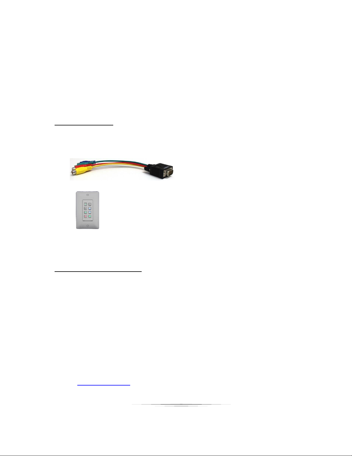
CA0054-1 8” VGA to 4 RCA Adaptor cable (YPbPr and Composite Video)
DXB-8 Button Backlit Wall Controller Panel available in black or white.
DXE-USB-H1 USB Host side (PC) extender unit for DXW-2EU.
DXE-USB-D1P USB Device side extender unit with 24v DC power supply for DXW-2EUH
Compatible HDBaseT Receivers
The DXW-2 Series is an HDBaseT technology product and should work with other HDBaseT receivers.
Please note if product does not supply POE remotely local 24v DC power supply (PS0053-1) must be
used. DXW-2 models will be limited to the capabilities of the receiver accordingly.
DXE-CAT-RX1 (Recommended for DXW-2 Model Only)
DXE-CAT-RX2 (Recommended for DXW-2, 2E, or 2EU)
DXE-CAT-RX3 / RX3C / RX3-A / RX3C-A (Recommended for DXW-2, 2E, or 2EU)
DXCI-4-HDBT1 (Recommend for DXW-2 Model Only)
DXCI-4-HDBT2E (Recommended for DXW-2, 2E, & 2EU)
Note: Go to www.auroramm.com for latest manual and firmware
1
Page 5
User Guide
INTRODUCTION
About
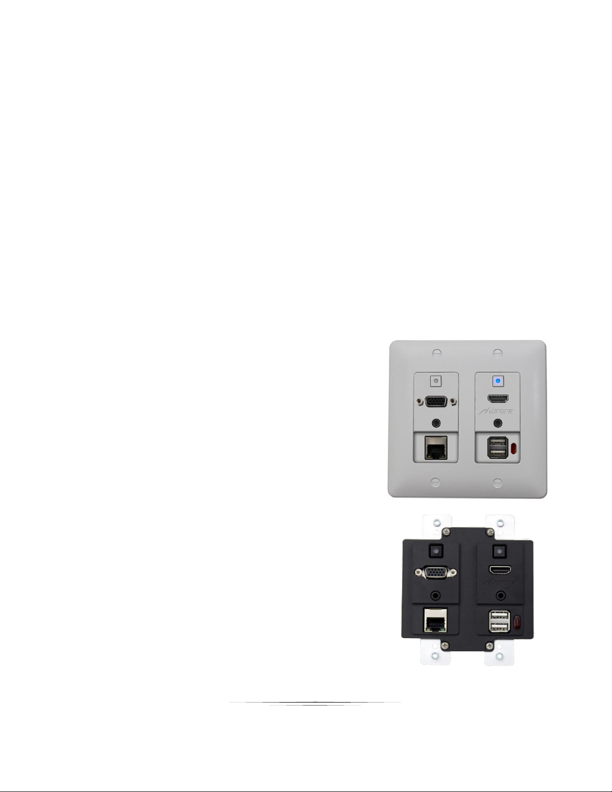
The DXW-2 Series available in white or black are 2 gang multi-input Decora
with HDBaseT CAT transmitter. Its ability to convert VGA (YPbPr, S-Video, Video) with audio to
HDMI locally and transmit the signal up to 600ft sets this unit apart from the competition. The
sources are remotely selectable via RS-232 commands sent through the matching receiver
device (DXE-CAT-RX, DXM Matrixes, etc). In addition, there is a LAN port (DXW-2E, DXW-2EU,
DXW-2EUH) for connection to the network without requiring a separate wall plate. The DXW-2EU
has two USB ports for powering USB devices and transmitting 480Mbps up to 220ft independently
to a different location. The DXW-2EUH has 2 USB Ports, top for host use (PC) and lower for
charging only and can extend up to 150ft. The DXW-2 Series can be remotely powered by the
receiver device and also has the ability to transmit IR signals via the sensor window on the front
of the unit for remote control of IR controllable devices. Overall, the DXW-2 saves money and
simplifies an installation by combining the functionality of a switcher, converter, and extender into
one neat package.
Features
1 HDMI Input with Audio for DVI
®
style wall plates
1 VGA with Audio Converted to HDMI
VGA can Accept YPbPr, S-Video, & Video
Programmable Buttons for Control of Displays
1 LAN Connector (DXW-2E, DXW-2EU, DXW-2EUH)
HDBaseT 600ft (183m) Extension
2 USB 2.0 Ports (DXW-2EU, DXW-2EUH)
USB Extends Independently (2EU 220ft, 2EUH 150ft)
1 IR Receiver (40ft Range)
Auto Sense, Buttons, RS-232 for Source Select
Buttons Backlight (Red, Green, Blue)
HDCP Compliant
Remote or Local Power (DXW-2EUH remote only)
Fits in Standard 2 Gang Outlet Box
Low Depth for Floor & Table Boxes
Warning: Do not plug RJ-45 HDBaseT output to non-HDBaseT compliant devices or damage may occur to
either product.
2
Page 6
User Guide
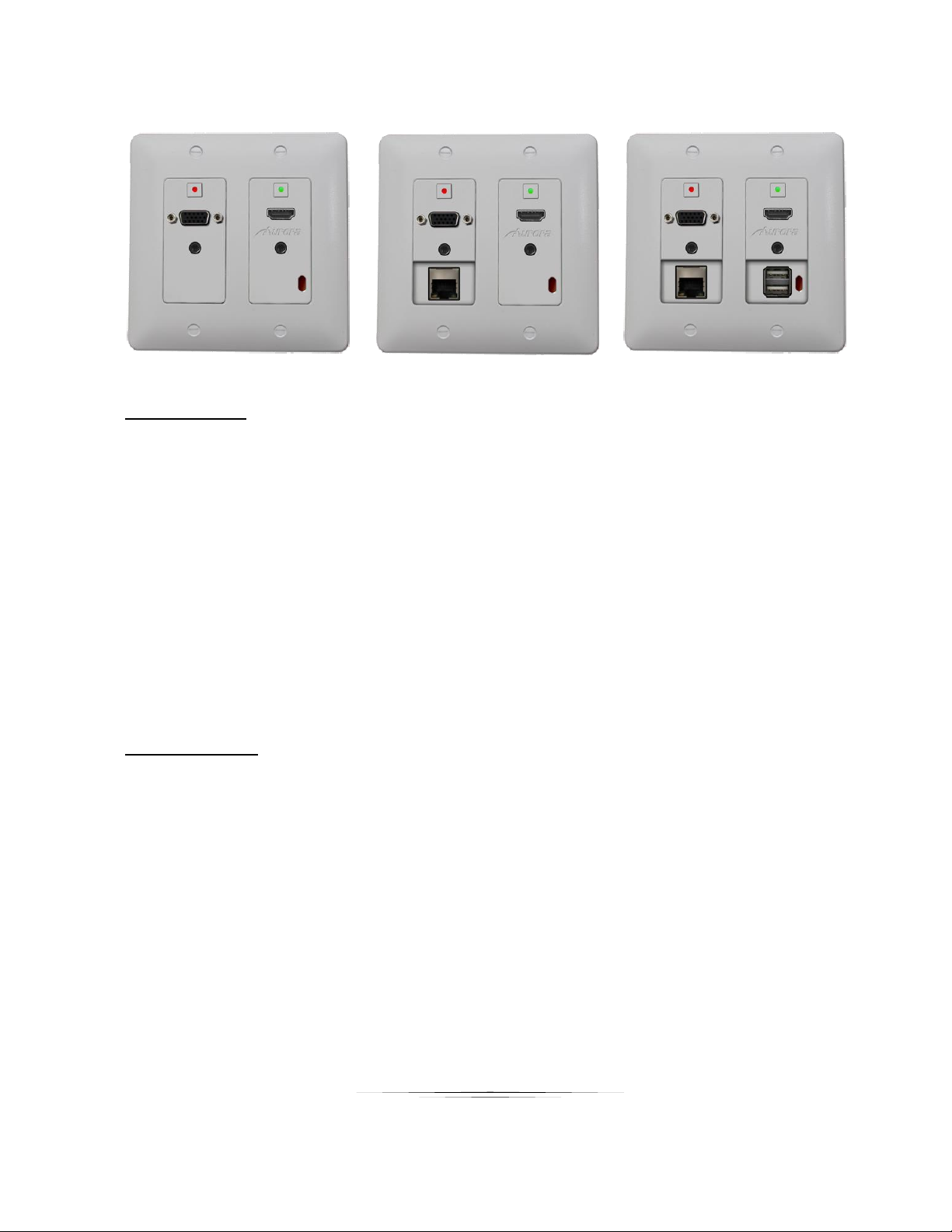
Front DXW-2, DXW-2E, DXW-2EU, DXW-2EUH
DXW-2 DXW-2E DXW-2EU / DXW-2EUH
Front Left Side
Button – The backlit button (red, green, or blue) will select the left side source.
DB15 VGA Connector – VGA up to 1080p can be input. Through the use of a breakout cable
YPbPr, Video, and S-Video can also be input. The DXW-2 will check for VGA signal, if no
signal, YPbPr, then Composite Video, and finally S-Video. When switching back and forth the
DXW-2 will remember the last source selected for faster switching. All analog sources will be
converted to HDMI and sent HDBaseT to the receiver unit. Note: See appendix for pin out
information.
3.5mm TRS Connector – Audio for the VGA connector sources to be embedded in HDMI
RJ-45 LAN Connector (DXW-2E, DXW-2EU, & DXW-2EUH) – 10/100 LAN via HDBaseT
receiver unit. Must use DXE-CAT-RX2 or RX3 for LAN function. Note only yellow LED is
active and will light solid when link and blink with activity.
Front Right Side
Button – The backlit button (red, green, or blue) will select the right side source.
HDMI Connector – Use with HDMI or DVI sources like Blu-ray players, laptops, etc.
3.5mm TRS Connector – Audio for DVI source to embed and turn into HDMI.
Dual USB Connector (DXW-2EU / 2EUH) – USB 2.0 480Mbps and supplies up to 1A of
power between both ports. Note the power comes from the HDBaseT extender or local
supply not the USB extender. Great for charging port of USB devices like phones and certain
tablets. If used for extender it must be used with DXE-USB-H1 (2EU 220ft) or DXE-USB-D1P
(2EUH 150ft) and is wired separate of the HDBaseT CAT cable. Please note iPhone® & iPad®
devices require use of DXE-USB-H1 (2EU model only) connected to PC in order to charge or
maintain power (iPad®). DXW-2EUH top port is for PC (Host Type A to Type A cable is
supplied) and lower port is charging only.
IR Remote Window – Can receive IR remotes at 38kHz and transmit to other end. Receives
signals up to 40ft away.
3
Page 7
User Guide
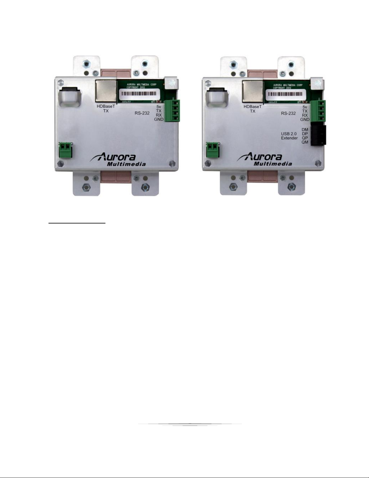
Rear Panel DXW-2, DXW-2E, DXW-2EU, DXW-2EUH
.
Rear Connections
24V DC – Power connector for 24V DC power supply. If remote device can supply power
over HDBaseT then the local power is not required. Currently all receiver types from Aurora
supply power over the HDBaseT.
HDBaseT – CAT 5e/6/6A cables can be used. For longest distance over 600ft use CAT 6A
shielded. This connector is right angle for low depth applications.
RS-232 – Connect RS-232 device up to 115k baud. Note there is a 5v line as it is designed to
power the DXB-8 8 button wall plate. Note: The DXW-2EUH model will use 2 position green
power connector location as DEV_DET input and ground so only remote power from receiver
will work.
USB Extender – The black 4 pin 3.5mm Euro style connector is a separate extender to work
with the DXE-USB-H1 for 2EU model or DXE-USB-D1P for 2EUH model. It will work up to
220 feet for the 2EU and 150ft for the 2EUH with CAT 6 cable allowing the PC to be located
elsewhere from the video.
Note: Some 2 gang electrical boxes or mud rings have curved or beveled corners that may
prevent the DXW-2 from properly fitting. Make certain to use a brand that fits the full
dimensions listed in the specification section.
4
Page 8
User Guide
APPLICATIONS
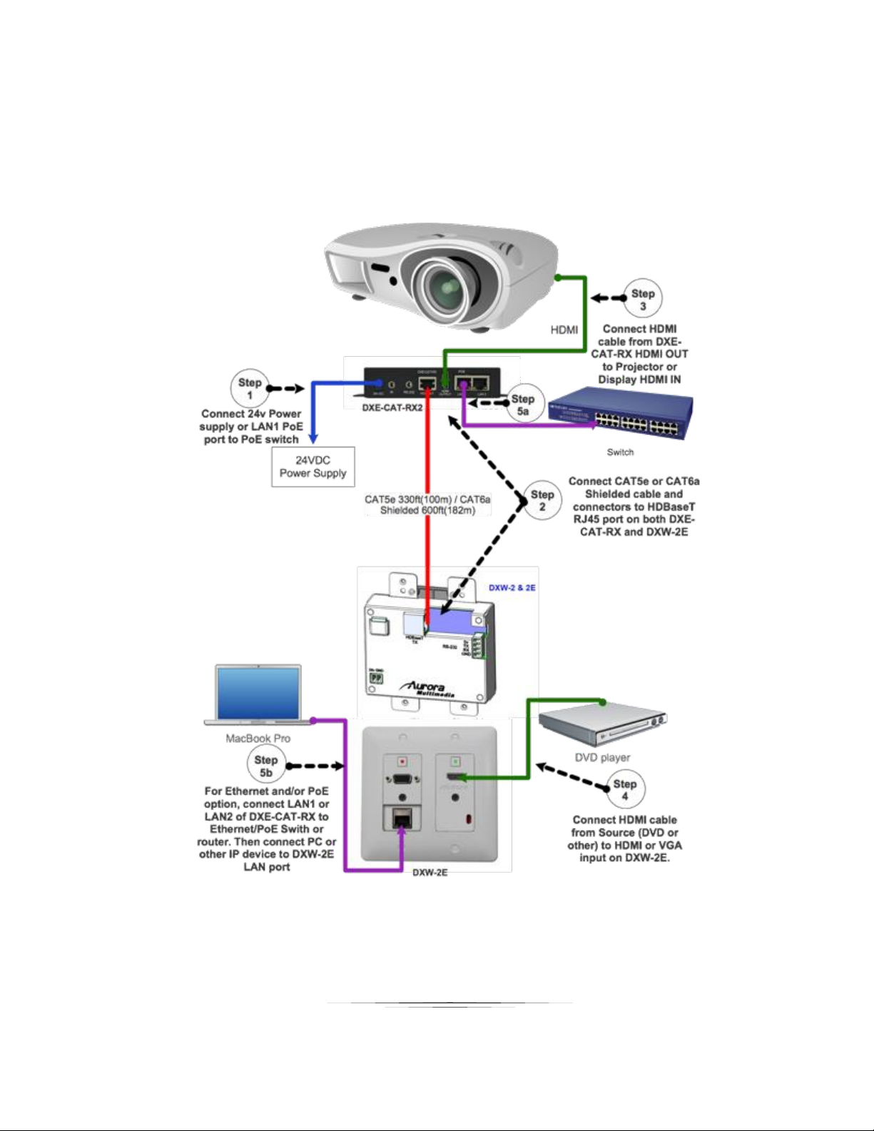
Example 1 Typical DXW-2 Transmitter to RX Receiver
5
Page 9
User Guide
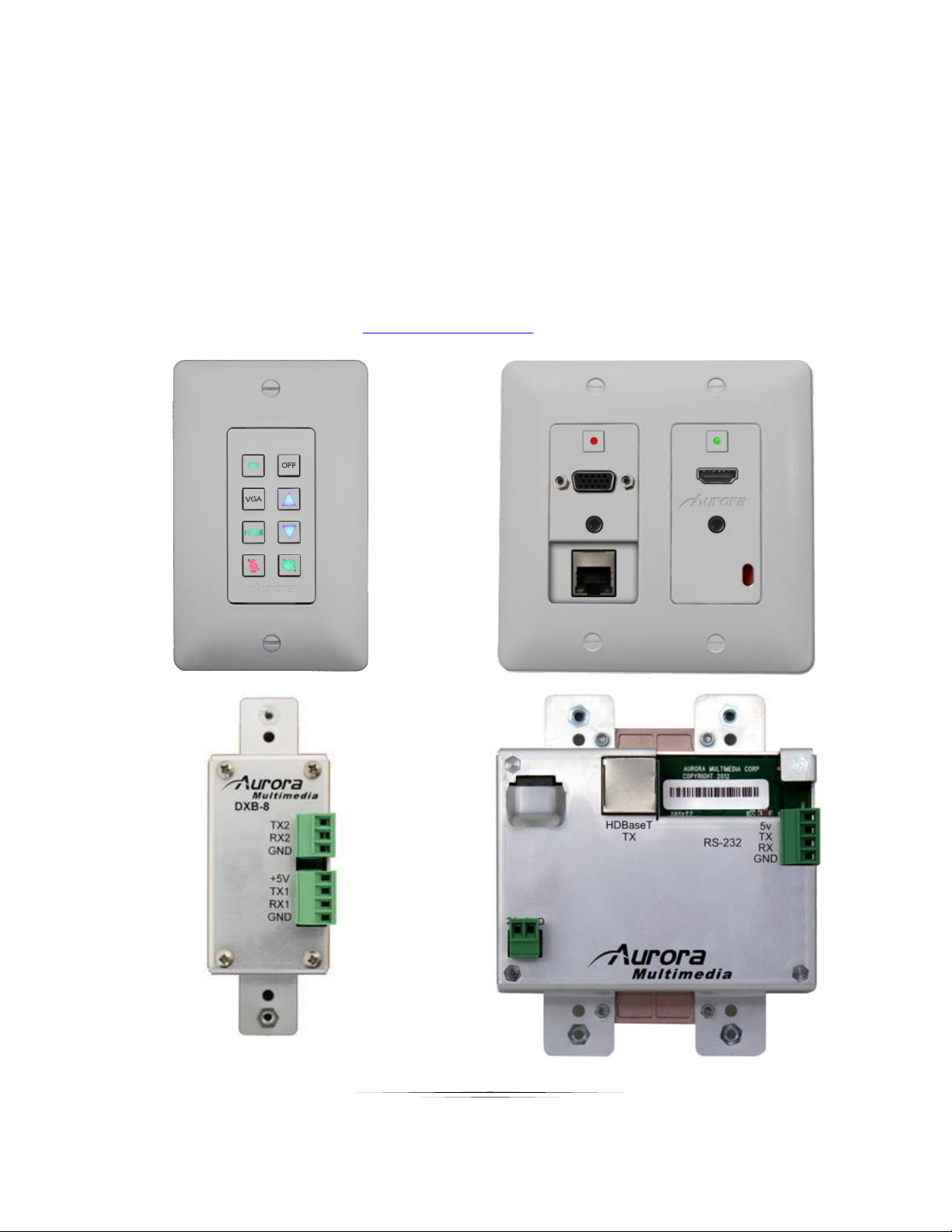
Example 2 DXB-8 Button Wall Control to DXW-2
DXB-8 wall controller connected to the DXW-2 series. The DXB-8 serial port will
connect and draw power from the DXW-2 via the 4 pin RS-232 connection. Any serial
command can be programmed into the DXB-8 at any baud rate and sent through the
DXW-2 to the DXE-CAT-RX receivers. This allows not only the switching of the DXW-2
to be controlled but the remote display device as well. Make certain the baud rates are
set the same on the DXW-2 and the DXB-8. More information on the DXB-8 can be
found on the Aurora website www.auroramm.com
6
Page 10
User Guide
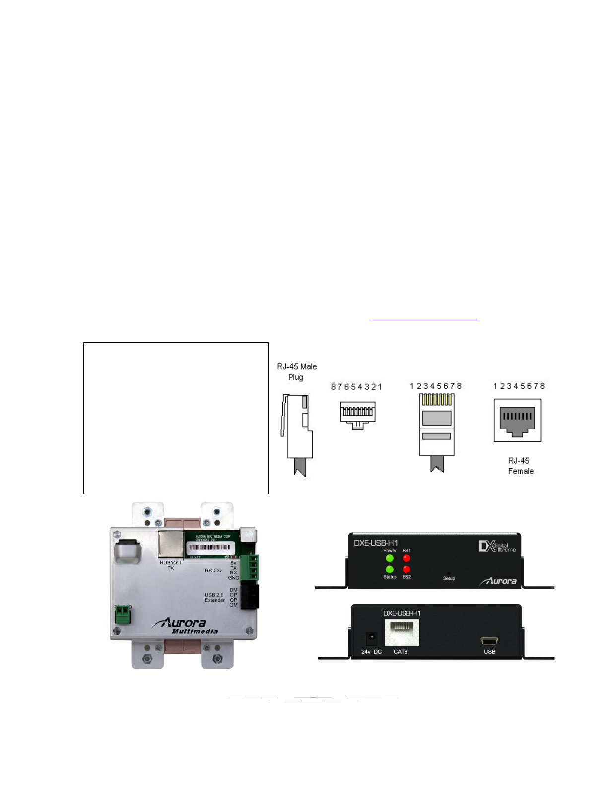
Example 3 DXW-2EU Connected to DXE-USB-H1
1- DM
2- DP
3- 24V DC (Do not connect)
4- Host Detect (Do not connect)
5- Device Detect (Connect to 5V)
6- GND
7- QM
8- QP
The DXE-USB-H1 (Host Unit) will be located by the computer using the Mini USB Type
B to USB Type A Male cable that is supplied with the DXE-USB-H1. The 24v DC is not
required to be connected when used with the DXW-2EU. Power will be drawn from the
computer. The DXW-2EU will supply 5v to the USB connectors for local charging even if
the DXE-USB-H1 is not connected as it derives its power from the HDBaseT
connection. Please note many tablet devices have proprietary charging circuits and may
not fast charge.
The RJ-45 of the DXE-USB-H1 will connect to the DXW-2EU USB 2.0 3.5mm black
connector and the RS-232 3.81mm green connector (power & ground only). The pin-out
for the RJ-45 is noted below.
More information on the DXE-USB-H1 can be found at www.auroramm.com
7
Page 11
User Guide
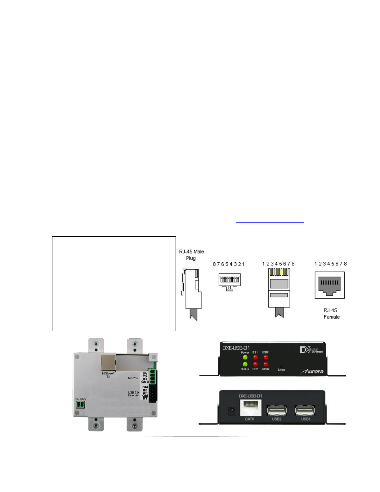
Example 4 DXW-2EUH Connected to DXE-USB-D1P
1- DM
2- DP
3- GND (Must be D1P Model only)
4- Host Detect (Connect to 5V)
5- Device Detect (Connect to DT)
6- GND
7- QM
8- QP
The DXE-USB-D1P (Device Unit with 24v DC supply) will be located by the product
using the USB Type A connectors (ex. Keyboard, mouse, etc). The DXW-2EUH is the
opposite of the 2EU model and will not supply 5v to the USB connectors for local
charging as it is a Host. The top USB port of the DXW-2EUH is the Host and the bottom
connector is not used. The top Host port will connect to the PC USB port via supplied
USB Type A to Type A cable.
The RJ-45 of the DXE-USB-D1P will connect to the DXW-2EUH USB 2.0 3.5mm black
connector, and the RS-232 3.81mm green connector (5v). The pin-out for the RJ-45 is
noted below.
Note: The DXW-2EUH must be paired with the DXE-USB-D1P for USB proper operation. The
main difference of the D1 vs D1P is the ability to power locally with 24v DC. The D1 does not
have this as it is specifically designed to pair with the H1.
More information on the DXE-USB-D1P can be found at www.auroramm.com
8
Page 12

User Guide
OPERATION
Source Selection
The DXW-2 Series has the ability to change between the VGA port and the HDMI via front buttons,
RS-232, and Auto-Sense. Once a source is selected the display will lock within a few seconds.
The time to lock depends on the display but typical time can be from 3-5 seconds. Keep in mind
the DXW-2 series does not scale so what comes in is what will go back out for both the VGA and
the HDMI. Most modern displays have scalers and the DXW-2 Series can handle resolutions up
to 1080p.
DVI Input
For DVI use a DVI to HDMI cable. If the source is DVI the HDMI input will try to auto detect. If
detected the analog audio below the HDMI connector will become active. Holding the HDMI
button for two seconds will force analog audio and will be confirmed with the button LED
illuminating cyan. To revert back press either button accordingly and the LED will light to its
defined prior color.
YPbPr Input
For YPbPr use a VGA to YPbPr cable (CA0054-1). When VGA side is selected the DXW-2 will
automatically see there is no VGA sync signals and try to lock to YPbPr. If present it will then lock
and display image. Note when using YPbPr auto sense will not work even if enabled. Auto sense
will only work with VGA and HDMI signals.
Auto-Sense
The DXW-2 Series has Auto-Sense capability. Auto-Sense will automatically switch to the last
HDMI or VGA input connected provided a hot-plug is provided from the source device. The DXW2 factory default is enabled but can be disabled and saved in non-volatile memory via RS-232
command. In addition, the front button selection or RS-232 control will allow the DXW-2 to switch
away until another new input is detected. For example, if a user has a laptop plugged into the
VGA port and then connects a Blu-ray® player to the HDMI, the DXW-2 will automatically switch
to the HDMI input. If after that the laptop is disconnected or signal is removed with function keys
and reconnected the DXW-2 will switch back to the laptop. If an RS-232 command is received to
switch to the opposite input the unit will do so as well. Whenever a source is changed the LED
on the button will follow and the RS-232 ports will send a response string to let a remote device
know that a change has occurred.
9
Page 13

User Guide
EDID Handling
The HDMI port will retrieve the EDID from the destination device (ex. Projector, LCD, Matrix,
etc) via the HDBaseT connection to the receiver unit. The VGA port will use an internal EDID
specific to the capabilities of the DXW-2 VGA port with 1080p being the recommended default.
AWV™ (Audio without Video)
The DXW-2 Series has the ability to send audio with a video signal being present on the VGA
audio connector. This is done by sending a 640 x 480 VGA signal when no signal is available so
audio can still be heard through the HDMI input on the display or amplifier. Keep in mind if this
feature is enabled (see RS-232 commands) installations relying on loss of signal to turn display
on and off will not work. The DXW-2 factory default is disabled but can be enabled and saved in
non-volatile memory via RS-232 command.
Factory Reset
Holding both buttons for 5 seconds will restore factory defaults. This will be confirmed by both
buttons turning cyan. Keep in mind all stored settings into the non-volatile memory will revert
back to the factory defaults of each function accordingly.
10
Page 14
User Guide
SERIAL COMMANDS
Command
String Format
Information
Baud Rate Setup
Command
!20BRy,a,b<cr>
y = port number = 1 or 2 (1 is HDBaseT, 2 is Rear Port)
a = baud rate = 2400, 4800, 9600, 19200, 38400, 57600,
115200
b = bits, parity, stop = 8N1, 8E1, 8O1
Factory Default is 9600 8N1
Button LED Setup
!20BLy,z1,z2 <cr>
y = 1-2 (1 is VGA, 2 is HDMI)
z1 = Released LED State = R, G, B, N (R = Red, G = Green,
B = Blue, N = None)
z1 = Pushed LED State = R, G, B, N (R = Red, G = Green,
B = Blue, N = None)
Factory Default is off for release and blue for push.
Button Push
!20BPx<cr>
x = 1-2 (1 is VGA, 2 is HDMI) power up default is HDMI
Auto Sense mode
!20ASx<cr>
X = 1 (on) or 0 (off) Factory Default is enabled.
AWV™ Mode
!20AWx<cr>
X = 1 (on) or 0 (off) Factory Default is disabled.
USB Length
!20ULx<cr>
X = 1-3
1 = < 197’ (60m)
2 = 180’ (60m) to 220’ (67m)
3 = 220’ (67m) to 262’ (80m)
Distances longer than 220’ require cable grade 6A or
higher.
HDMI IN HDCP Disable
!20DHx<cr>
X=0 (Normal) or 1 (HDCP Input disable)
Button Press Disable
!20NPx<cr>
X=0 (Normal) or 1 (Disable Physical Button Press)
Button Press Serial
String
!20PSp,b,z<cr>
p = serial port 1 or 2
b = button number 1 or 2
z = URL encoded serial string
eg
RS-232 Commands
! - Command, ? - Query, ~ Response
<cr> = 0x0D Hex / 13 Decimal
20 = Fixed Address for DXW. DXW will not pass through serial to other port when it sees it is a
specific command intended for the DXW. Command will work without address, however, the
response will appear on both ports.
11
Page 15
User Guide
!20PS1,2,Hello World<cr> will send "Hello World" out
the extender serial port on an HDMI button press.
Both ports default to ~20BP1%0d" for button 1 and
"~20BP2%0d" for button 2. Setting empty string will
disable the communication.
Cable Disconnect Timer
String
!20CSp,d,z<cr>
where p = serial port 1 or 2
d = is the no cable msg trigger delay in seconds > 0
z = URL encoded serial string for no cable detected
eg
!20CS2,10,No cable%0d%0a<cr> will send "No cable"
followed by a CR and LF out the local serial port 10
seconds after the cables are removed.
Both ports default to no message setting empty string
will disable the communication.
Query Firmware
Revision
?20FM<cr>
Query Button State
?20BP<cr>
Query Button LED
?20BLy<cr>
y = 1-2 (1 is VGA, 2 is HDMI)
Query Auto Sense
Mode
?20AS<cr>
Query AWV™ Mode
?20AW<cr>
Query USB Length
?20UL<cr>
Query HDMI IN HDCP
Disable
?20DH<cr>
Query Button Press
Disable
?20NP<cr>
Query Button Press
Serial String
?20PSp,b<cr>
Query Cable
Disconnect Timer
String
?20CSp<cr>
RS-232 commands can be sent to the local RS-232 port or the remote RS-232 port at the receiver.
12
Page 16
User Guide
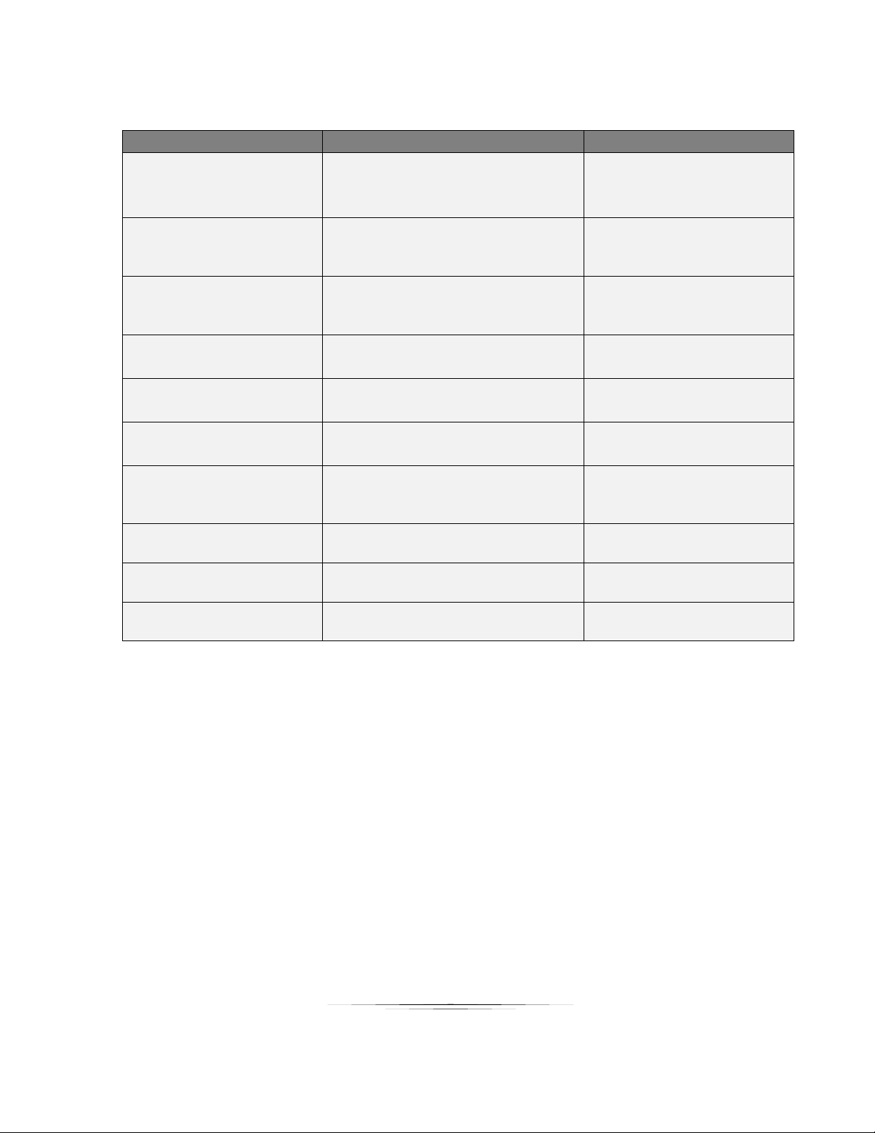
RS-232 Command Usage
Example
Example String
Example Response
Baud Rate Setup Command
Set Port 1 Baud Rate to 96008N1.
!20BR1,9600,8N1<cr>
~20BR1,9600,8N1<cr>
Button LED Setup
Set button 1 to Release to green &
Push to blue.
!20BL1,G,B<CR>
~20BL1,G,B<CR>
Button Push
Trigger button 2 (HDMI)
!20BP2<cr>
~20BP2<cr>
Auto Sense Mode
Turn on Auto Sense
!20AS1<cr>
~20AS1<cr>
AWV™ Mode
Turn off AWV™ Mode
!20AW0<cr>
~20AW0<cr>
Query Firmware Revision
Query the firmware revision
?20FM<cr>
~20FM-2.1<cr>
Query Button State
Check button state.
?20BP<cr>
Button 2 (HDMI) is selected in
this example.
~20BP2<cr>
Query Button LED
Check button press 1 LED state.
?20BL1<cr>
~20BL1,G,R<CR>
Query Auto Sense
Check Auto Sense State
?20AS<cr>
~20AS0<cr>
Query AWV™ Mode
Check AWV™ Mode State
?20AW<cr>
~20AW0<cr>
13
Page 17
User Guide
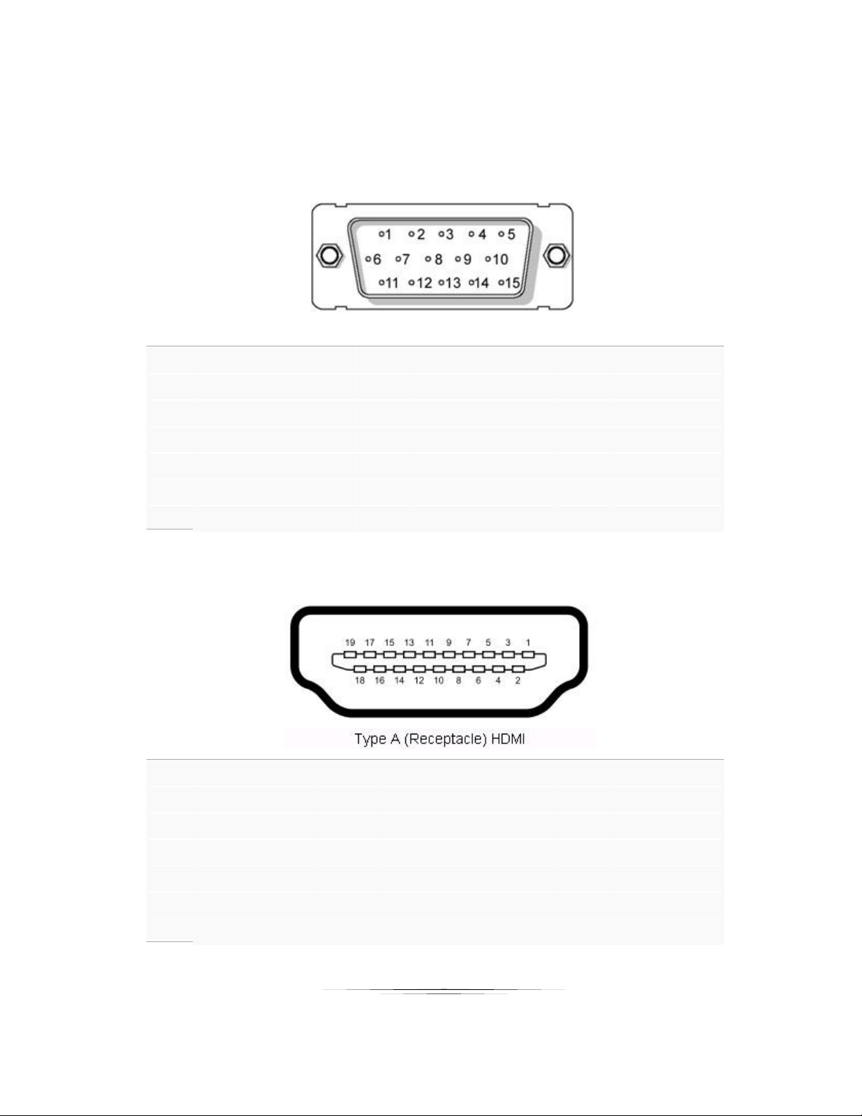
CONNECTOR PIN DEFINITION
Pin 1 Red (Pr)
Pin
8
Ground
Pin
15
SCL
Pin 2 Green (Y, S-Video C)
Pin
9
5v
Pin 3 Blue (Pb)
Pin
10
SYNC Ground
Pin 4 Composite (S-Video Y)
Pin
11
NC
Pin 5 Ground
Pin
12
SDA
Pin 6 Ground
Pin
13
Horizontal Sync
Pin 7 Ground
Pin
14
Horizontal Sync
Pin 1 TMDS
Data2+
Pin
8
TMDS Data0 Sh
ield
Pin
15
SCL
Pin 2 TMDS Data2 Sh
ield
Pin
9
TMDS
Data0–
Pin
16
SDA Pin 3 TMDS
Data2–
Pin
10
TMDS
Clock+
Pin
17
DDC/CEC Gr
ound
Pin 4 TMDS
Data1+
Pin
11
TMDS Clock Sh
ield
Pin
18
+5 V Powe
r
Pin 5 TMDS Data1 Sh
ield
Pin
12
TMDS
Clock–
Pin
19
Hot Plug
Detect
Pin 6 TMDS
Data1–
Pin
13
CEC
Pin 7 TMDS
Data0+
Pin
14
Reserved (N.C. on
device)
VGA DB15HD
HDMI
14
Page 18
User Guide
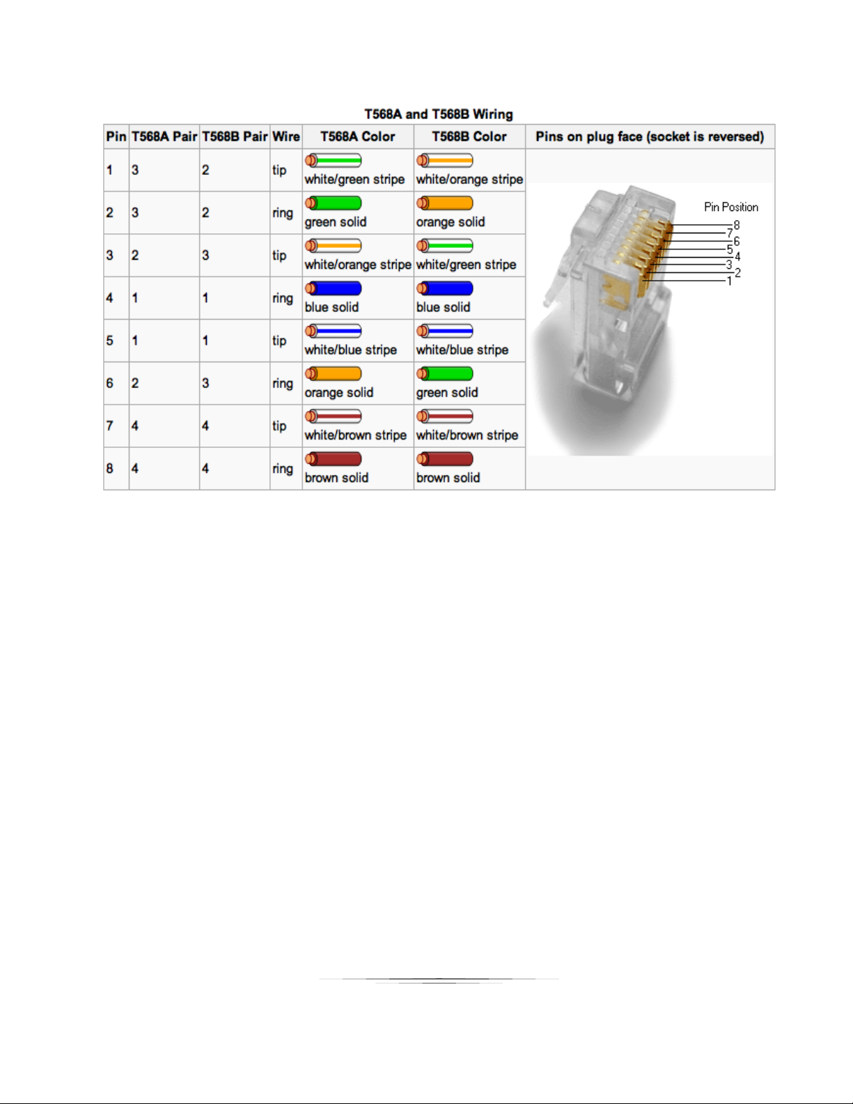
CAT5e/6/6A
1. All transmission distances are measured using Belden 1583A CAT5e 125MHz Solid UTP cable. The transmission distance is
defined as the distance between the video source and the display.
2. To reduce the interference among the unshielded twisted pairs of wires in UTP cable, you can use shielded STP cables to
improve EMI problems, which is worsen in long transmission.
15
Page 19
User Guide
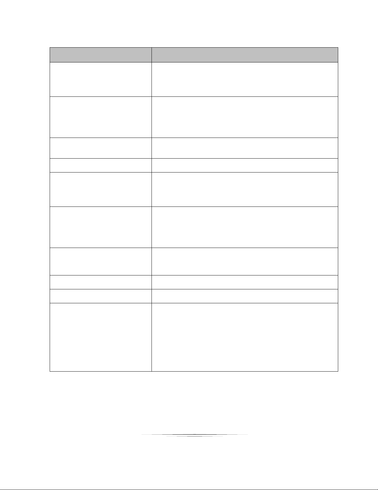
APPENDIX 1 Troubleshooting
Problem
Solution
1. No Video Signal.
a. Check that the power plug is properly inserted into a functioning power
outlet. Keep in mind the DXW-2 can be powered locally or remotely via
HDBaseT POE.
b. Make certain source is on.
c. Verify pin-out of connector at each end.
2. LED is not lit on either button
a. Check 24v power supply is plugged in locally or at the far end receiver
unit.
b. Check to see if Wall supply is plugged into wall outlet.
c. Make certain wall outlet has power.
d. Make certain RS-232 command for LED state is not set to none for
both buttons.
3. LAN Not Working
a. Verify receiver unit is capable of LAN.
b. If using with DXM G2 Series card cage LAN will not work as it does
not have that capability.
4. IR not working
a. Verify using proper emitter at receiver unit. Note the DXW-2 IR receiver
is 38KHz. Use Aurora branded accessories for best results.
5. USB not charging
a. Total power between the 2 ports is 5 watts. If exceeded the fuse
protection will kick in until within specification. Try connecting one
device at a time to make certain it works before plugging in 2 devices.
b. iPad® & iPhone® require DXE-USB-H1 connected to PC in order to
charge. iPad® will maintain power but not charge.
6. USB not working
a. Make certain DXE-USB-H1 is connected to PC
b. Make certain DXE-USB-D1P is powered.
c. Make certain the cabling is correct and distance is not exceeded.
d. Make certain proper power supply wattage is being used to power both
DXW-2 and the receiver. Refer to technical specifications for more info
on power consumption.
7. Unit not working
a. Check if remote receiver is supplying power.
b. Make certain proper power supply wattage is being used to power both
DXW-2 and the receiver. Refer to technical specifications for more info
on power consumption.
8. Display will not turn on / off when
no signal is present
a. Turn off AWV™ feature using RS-232 command as it will put out a 640
x 480 signal if no signal is present.
9. Certain functions listed in manual
do not function
a. Make certain unit has latest firmware
10. 720p or 1080p is too big for
screen (Over scanned)
a. The DXW-2 does not scale. Check the display’s settings for over-scan
mode. Displays cannot tell the difference between a video source and
a PC source. In turn they usually have a setting in the menus to deal
with this. Check under Aspect Ratio settings, PC / Video mode, etc.
Note if you plug the VGA directly into display and compare to input of
DXW-2 it is not a proper test. The DXW-2 is connected through the
HDMI input not VGA of the display. The display will handle the signal
different as the display will know not to over scan a VGA signal. HDMI
by definition is treated as a video source first and as a PC source
secondary when dealing with video resolutions.
Warning: Do not plug RJ-45 HDBaseT output to non-HDBaseT compliant devices
or damage may occur to either product.
16
Page 20
User Guide
APPENDIX 2 Firmware Update
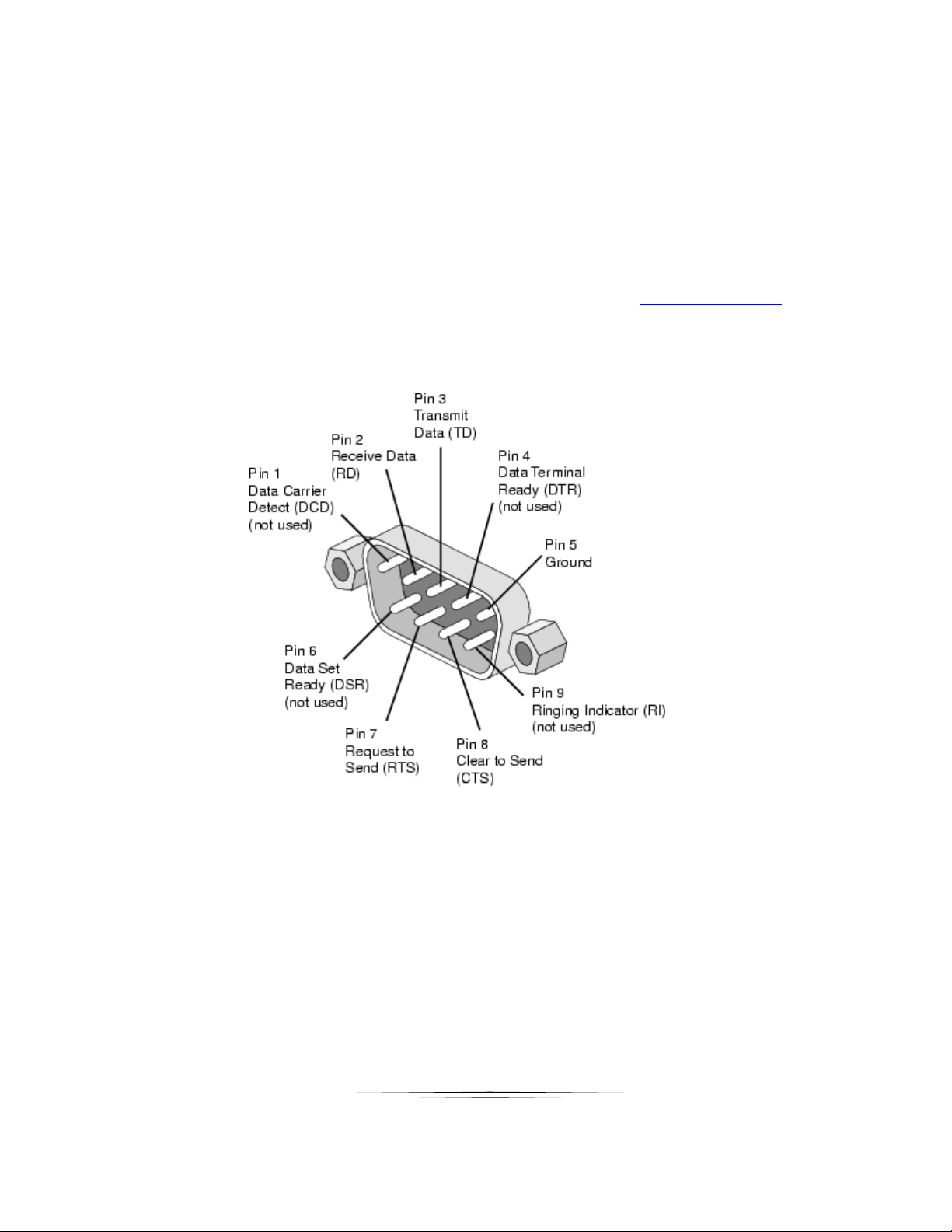
PC DB-9 RS-232 Serial Port
DXW-2 Update Utility
DXW-2 Update Software requires a serial cable connected in a null (RX to TX, TX to RX, GND to GND)
configuration to a PC. The firmware can be updated directly at the DXW-2 rear serial port or it can be
updated via HDBaseT receiver RS-232 port. To force update mode press and hold both front buttons
while applying power. Then use utility to transfer file which can be found at www.auroramm.com
17
Page 21

User Guide
APPENDIX 3 Supported Timing
525p@60
640x480@60
1152x864@75
625p@50
640x350@70
1280x768@60
720p@60
640x350@85
1280x800@60
720p@50
1280x960@60
720p@24
640x480@75
1280x960@85
720p@25
640x480@85
720p@30
720x400@70
1080i@60
720x400@85
1080i@50
1360*768@60
1080i@100
1440x900@60
1080p@60
1400x1050@60
1080p@50
800x600@75
1600x1200@60
1080p@30
1680x1050@60
848x480@60
1920x1200@60
1080p@24
1024x768@43
1080p@25
1024x768@60
1024x768@85
VGA Port Supported Timing
18
Page 22
User Guide
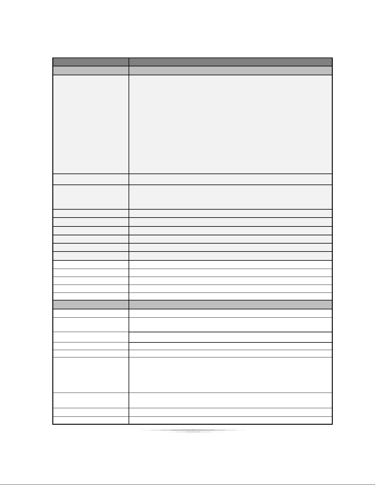
APPENDIX 4 Technical Specifications
Model Name
DXW-2
Technical
DXW-2 Series
Video Distance (HDBaseT)
328ft 100m – 1080p 60Hz 24 & 36bit CAT 5e/6/6a/7
328ft 100m – 1080p 60Hz 48bit CAT 6a/7
328ft 100m – 4k2k 30Hz CAT 6a/7
230ft 70m – 1080p 60Hz 48bit CAT 5e/6/6a/7
230ft 70m – 4k2k 30Hz CAT 5e/6/6a/7
500ft 152m - 1080p 60Hz 24bit (Long Reach Mode) CAT 6
600ft 183m - 1080p 60Hz 24bit (Long Reach Mode) CAT 6A
CAT 5e/6 will achieve 328ft 100m for pixel clock <=225MHz
CAT 5e/6 will achieve 230ft 70m for pixel clock >225MHz
CAT 6a/7 will achieve 328ft 100m for pixel clock >225MHz
USB 2.0 Distance
DXW-2EU 220ft, DXW-2EUH 150ft using CAT 6
Max Resolution
1080p 60Hz
1920 x 1200 @ 60Hz
4k x 2k @ 30Hz
Color Depth
24bit 5e/6/6a/7, 36bit 5e/6, 48bit 5e/6/6a/7
RS-232
300 - 115kbps
IR Window
38kHz 40ft range
LAN
10/100
HDMI
3D, HDCP Compliant
Front Selections
2 Backlit Buttons (Red, Green, Blue)
LAN Connectors
8P8C with 2 LED indicators (Only yellow LED is active)
HDBaseT Connector
RJ-45 WE/SS 8P8C Right Angle
RS-232 Connector
4 pin 3.81mm Euro
HDMI Connector
Type A 19 pin
Power Connector
2 pin 3.81mm Euro
Mechanical
DXW-2 Series
Housing
Plastic front with aluminum rear enclosure
Dimensions
[L x W x D]
3.728”x4.331”x1.404”
Note: Wall box portion depth 1.04”
Weight
.38lbs
Mounting
Wall-mounting Decora® 2 Gang
Power supply
24V DC
Power consumption
DXW-2 & DXW-2E 6 Watts [max], DXW-2EU / 2EUH 11Watts (5 Watts for USB Ports)
Important: If DXW-2EU is drawing power from the receiver it will require 20 watt or
better power supply. Always check the ratings for transmitter and receiver and
add together. The result determines required wattage and Aurora power supply
needed.
Operation temperature
0~40C [32~104F]
Storage temperature
-20~60C [-4~140F]
Relative humidity
20~90% RH [no condensation]
19
Page 23
User Guide
Package Contents
1x DXW-2 or DXW-2E or DXW-2EU / 2EUH accordingly
1x Paintable White Wall Plate
1x User Manual
Options
PS0053-1 24v DC 15.5 Watt power Supply
PS0062-1 24v DC 24 Watt power Supply
CA0054-1 8” VGA to 4 RCA Adaptor cable (YPbPr and Composite Video)
Specifications subject to change without notice.
20
Page 24

User Guide
APPENDIX 5 Cabling
Aurora extender products have been tested utilizing shielded cabling. Although our products will
work fine without shielded cable it is highly recommended for environmental reasons as the
signals are high frequency and can radiate as well as be susceptible to external frequencies
and possibly cause noise or disruption in the image. Unshielded cabling will work fine in a
conduits as it will provide the shielding. We have found not all cable is created equal even
though they appear similar. This can affect distance and overall performance. Below is a list of
cables that have been officially tested with our products by the manufacturer of the cable.
West Penn Wire
CAT 6 Shielded - HDBaseT Certified - Only in Black
4246F – CMR, 254246F – CMP (Plenum)
CAT 6a Shielded HDBaseT Certified - Only in Black
4246AF – CMR, 254246AF – CMP (Plenum)
Both CAT 6 and CAT 6a Shielded Cables utilized a Modular Plug Kit:
90170-BI - Includes: 100 Connectors, 100 Boots, Crimp Tool, External round Crimp Tool, Strip Tool
CAT 6 Unshielded - Colors
4246 – CMR, 254246 - CMP (Plenum)
Connector: 32-6EZP
CAT5e Shielded - Blue or Gray
4245F – CMR, 254245F - CMP (Plenum)
Connector: 32-EZSTP
CAT 5e Unshielded- 12 Colors
4245-CMR, 254245 - CMP (Plenum)
Connectors: 32-EZP
21
Page 25

User Guide
APPENDIX 6 Warranty
Limited 3 Year Warranty
Aurora Multimedia Corp. (“Manufacturer”) warrants that this product is free of defects in both materials and
workmanship for a period of 3 years as defined herein for parts and labor from date of purchase. This Limited Warranty
covers products purchased in the year of 2009 and after. Motorized mechanical parts (Hard Drives, DVD, etc),
mechanical parts (buttons, doors, etc), remotes and cables are covered for a period of 1 year. Touch screen displays
are covered for 1 year; touch screen overlay components are covered for 90 days. Supplied batteries are not covered
by this warranty. During the warranty period, and upon proof of purchase, the product will be repaired or replaced (with
same or similar model) at our option without charge for parts or labor for the specified product lifetime warranty period.
This warranty shall not apply if any of the following:
A. The product has been damaged by negligence, accident, lightning, water, act-of-God or mishandling; or,
B. The product has not been operated in accordance with procedures specified in operating instructions: or,
C. The product has been repaired and or altered by other than manufacturer or authorized service center; or,
D. The product's original serial number has been modified or removed: or,
E. External equipment other than supplied by manufacturer, in determination of manufacturer, shall have
affected the performance, safety or reliability of the product.
F. Part(s) are no longer available for product.
In the event that the product needs repair or replacement during the specified warranty period, product should be
shipped back to Manufacturer at Purchaser's expense. Repaired or replaced product shall be returned to Purchaser
by standard shipping methods at Manufacturer's discretion. Express shipping will be at the expense of the Purchaser.
If Purchaser resides outside the contiguous US, return shipping shall be at Purchaser's expense.
No other warranty, express or implied other than Manufacturer's shall apply.
Manufacturer does not assume any responsibility for consequential damages, expenses or loss of revenue or property,
inconvenience or interruption in operation experienced by the customer due to a malfunction of the purchased
equipment. No warranty service performed on any product shall extend the applicable warranty period. This warranty
does not cover damage to the equipment during shipping and Manufacturer assumes no responsibility for such
damage.
22
Page 26

User Guide
This product warranty extends to the original purchaser only and will be null and void upon any assignment or
Aurora Multimedia Corp.
205 Commercial Court
Morganville, NJ 07751
Phone: 732-591-5800 Fax: 732-591-6801
www.auroramm.com
23
 Loading...