

USERS GUIDE
www.auroramm.com
Manual Number: 190709 | Firmware Rev: X.X
DXM G4 Series
Digital Xtreme Card Chassis 8x8 & 16x16

ii
USERS GUIDE
www.auroramm.com
SAFETY INSTRUCTIONS
Please review the f ollowing safety prec autions. If this is the f irst time using this model, then read this manual before
installing or using the prod uct. If the product is no t functioning prop erly, please contact your local dealer or Aurora for
further instructions.
The lightning symbol in the triangle is used to alert you to the presence of dangerous voltage inside the product
that may be sufficient to constitute a risk of electric shock to anyone opening the case. It is also used to indicate
improper installatio n or handling of the product that could damage the electrical system in the produc t or in
other equipment attached to the product
The exc lamation po int in t he tri angle is used t o alert you to impor tant operati ng and m aintena nce inst ruction s.
Failure to follow these instructions could result in injury to you or damage to the product.
Be careful with electricity:
Power outlet: To prevent electric shock, be sure the electrical plug used on the product power cord
matches the electr ical outle t used to su pply po wer to t he Aurora product. U se onl y the po wer adapter and
power connection cables designed for this unit.
Power cord: Be sure the power cord is routed so that it will not be stepped on or pinched by heavy items.
Lightning: For protection from lightning or when the product is left unattended for a long period, disconnect
it from the power source.
Also follow these precautions:
Ventilation: Do not block the ve nti lat io n s lots if app licable on the pro duct or place any h ea v y obj ec t o n t op
of it. Blocking the air flow could cause damage. Arrange components so that air can flow freely. Ensure that
there is adequate venti lation if the product is placed in a stand or c abinet. Put the product in a proper ly
ventilated area, away from direct sunlight or any source of heat.
Overheating: Avoid stacking the Aurora product on top of a hot component such as a power amplifier.
Risk of Fire: Do not place unit on top of any easily combustible material, such as carpet or fabric.
Proper Connections: Be sure all cables and eq uipment are connected to the un it as described in this
manual.
Object Entry: To avoid electric shock, never stick anything in the slots on the case or remove the cover.
Water Exposure: To reduce the risk of fire or electric shock, do not expose to rain or moisture.
Cleaning: Do not use liqu id or aerosol clea ners to clean this un it. Always unplug the p ower to the device
before cleaning.
ESD: Handle this unit with proper ESD care. Failure to do so can result in failure.
FCC
This device complies with Part 15 of the FCC Rules. Operation is subject to the following two conditions:
(1) This device may not cause harmful interference.
(2) This device must accept any interference received, including interference that may cause undesired operation.
Trademarks
All trademarks in this document are the properties of their respective owners.

iii
USERS GUIDE
www.auroramm.com
TABLE OF CONTENTS
PACKAGE CONTENTS ............................................................................................................................................. 5
CARDS & ACCESSORIES ........................................................................................................................................ 6
INTRODUCTION ...................................................................................................................................................... 10
About ................................................................................................................................................................. 10
Features............................................................................................................................................................. 10
DXM-884 Front .................................................................................................................................................. 11
DXM-884 Rear ................................................................................................................................................... 12
DXM-1616 Front ................................................................................................................................................ 13
DXM-1616 Rear ................................................................................................................................................. 14
CARD FUNCTIONALITY ......................................................................................................................................... 15
Main Control Card ............................................................................................................................................. 15
HDBaseT Cards................................................................................................................................................. 16
HDMI Cards ....................................................................................................................................................... 19
SDI Cards .......................................................................................................................................................... 22
Front Panel Functionality ...................................................................................................................................... 25
Home Page ........................................................................................................................................................ 25
Basic Operation ................................................................................................................................................. 26
Video control ...................................................................................................................................................... 26
Audio control ...................................................................................................................................................... 27
EDID management ............................................................................................................................................ 27
System configuration ......................................................................................................................................... 29
RS232 settings ............................................................................................................................................... 30
General settings ............................................................................................................................................. 31
Web server .............................................................................................................................................................. 32
Video management ........................................................................................................................................... 32
Serial management ........................................................................................................................................... 36
EDID management ............................................................................................................................................ 37
Scene management .......................................................................................................................................... 37
Scene setup and overwiew................................................................................................................................ 37
UNDERSTANDING EDID ........................................................................................................................................ 39
EDID and its Importance ................................................................................................................................... 39

iv
USERS GUIDE
www.auroramm.com
CONNECTOR PIN DEFINITION ............................................................................................................................. 40
HDMI .................................................................................................................................................................. 40
CAT5e/6/6A ....................................................................................................................................................... 40
RS-232............................................................................................................................................................... 41
APPENDIX 1 ............................................................................................................................................................ 42
Troubleshooting ................................................................................................................................................. 42
APPENDIX 2 ............................................................................................................................................................ 43
Firmware Update ............................................................................................................................................... 43
APPENDIX 3 ............................................................................................................................................................ 45
Telnet and RS-232 Protocol............................................................................................................................... 45
APPENDIX 4 ............................................................................................................................................................ 53
Recommended Cabling ..................................................................................................................................... 53
APPENDIX 5 ............................................................................................................................................................ 54
Technical Specifications .................................................................................................................................... 54
APPENDIX 6 ............................................................................................................................................................ 56
Warranty ............................................................................................................................................................ 56

5
USERS GUIDE
www.auroramm.com
PACKAGE CONTE NTS
Please make sure the following items are included within your package. Contact your dealer if any
items are missing or damage d.
SKU
DXM-884-G4
IEC Power Cord
or
DXM-1616-G4
IEC Power Cord
Note: Go to www.auroramm.com for latest man ual and firmware.
6
USERS GUIDE
www.auroramm.com
Input Cards
DXCI-1-HDMI-G4
DXCI-1-HDBT1-G4
DXCI-1-HDBT2-G4
DXCI-1-SDI-G4
Output Cards
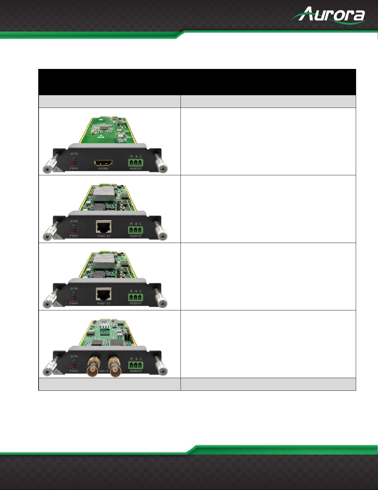
CARDS & ACCESSORIES
DIGITAL XTREME (GEN 4) – CARDS
1 Input HDMI 4K60 44 4 Card with Stereo Audio Input
1 Input HDBaseT 230' (70m) CAT 4K30 444/4K60 420 Card
1 Input HDBaseT 330' (100m) CAT 4K30 44 4/4K60 420 Card
1 Input 3G SDI Card

7
USERS GUIDE
www.auroramm.com
DXCO-1-HDMI-G4
DXCO-1-SHDMI-G4
DXCO-1-HDBT1-G4
DXCO-1-HDBT2-G4
DXCO-1-SDI-G4
Accessories
DXC-BLANK-G4
1 Output HDMI 4K60 444 with Stereo audio output Card
1 Output HDMI with 4K30 444/4K6 0 420 Scaler and Stereo
audio output Card. Allows for seamless switching.
1 Output HDBaseT 230' (70m) CAT 4K30 444/4K60 42 0 with
Stereo audio output Card
1 Output HDBaseT 330' (100m) CAT 4K30 444/4K60 420 with
Stereo audio output Card
1 Output 3G SDI with Stereo audio output Card
Blank Panel for Slot

8
USERS GUIDE
www.auroramm.com
External HDBT Boxes and Wall Plates
DXE-CAT-RX1-4K
DXE-CAT-RX2-4K
DXE-CAT-TX2-4K
DXW-2
DXE-CAT-TX1-4K
DIGITAL XTREME ACCESSORIES
230' (70m) HDBaseT Receiver (No PS)
328'/600' (100/183m) HDBaseT Receiver (No PS)
230' (70m) HDBaseT Transmitter (No PS)
328'/600' (100/183m) HDBas eT Transmitter (No PS)
2 Input HDBaseT Wall Plate (VGA & HDMI) - 230' (70m) CAT
Extender
DXW-2EU
2 Input HDBaseT Wall Plate (VGA & HDMI) - 230' (70m) CAT
Extender with LAN and Dual USB

9
USERS GUIDE
www.auroramm.com
Rack Mounts / Power Supplies / Cables
DXE-CAT-RK3BL
CA0052-F2T3R
CA0052-F3T2R
CA0052-M2T3R
DXE-CAT-RK3
3RU Rack Mount Kit for DXE-CAT-S1/S2/S2L (Fits up to 16
DXE-CAT units in 3RU space)
Blank Panels for DXE-CAT-RK3 Rack Mount
PS0053-1 24VDC PS w/US Adaptor (DXE-CAT)
3.5mm TRS to FEMALE DB9 2-TX 3-RX (Null Modem)
3.5mm TRS to FEMALE DB9 3-TX 2-RX
CA0052-M3T2R
3.5mm TRS to MALE DB9 2-TX 3-RX (Null Modem)
3.5mm TRS to MALE DB9 3-TX 2-RX

10
USERS GUIDE
www.auroramm.com
INTRODUCTION
About
The 4th Generation D igital X treme Series is a 4K60 4:4:4 capable modular matrix switch, card-based
chassis/frame, with a full complement of multimedia input and output cards. I/O cards have one
channel of Input or Output and are available with HDMI®, HDBaseT™, and SDI interfaces.
The DXM-G4 series is designed for ‘ease of ser vice’ as Input and Ou tput cards can be ‘hot swapped’,
allowing full serv iceability while power ed. Control of the DXM-G4 and connected dev ices is av ailable
through an integrated 5” touch scree n, Web Server, RS-232, and LAN. The system also provides
advanced EDID, HDCP, and data handling capabilities.
Features
• 20Gbps Per Port Backplane
• Advanced EDID Management
• Advanced HDCP Handling
• Remote Dia gnostics
• 5” Front Pa nel Touch Control
• Integrate d We b Ser ver Control
• PoH for HDBa seT™ Ports
• Units configurable 1-channels per card
• Break-away Audio Switching
• HDMI® I/O Ca r ds (Output Cards with Audio De-embedding, and Auto DVI Detect)
• HDBaseT™ CAT I/O Cards (Powers remote Tx/Rx units and passes RS-232, IR, &
Ethernet)
• Control Expansion Ports
• LAN and RS-232 Control

11
USERS GUIDE
www.auroramm.com
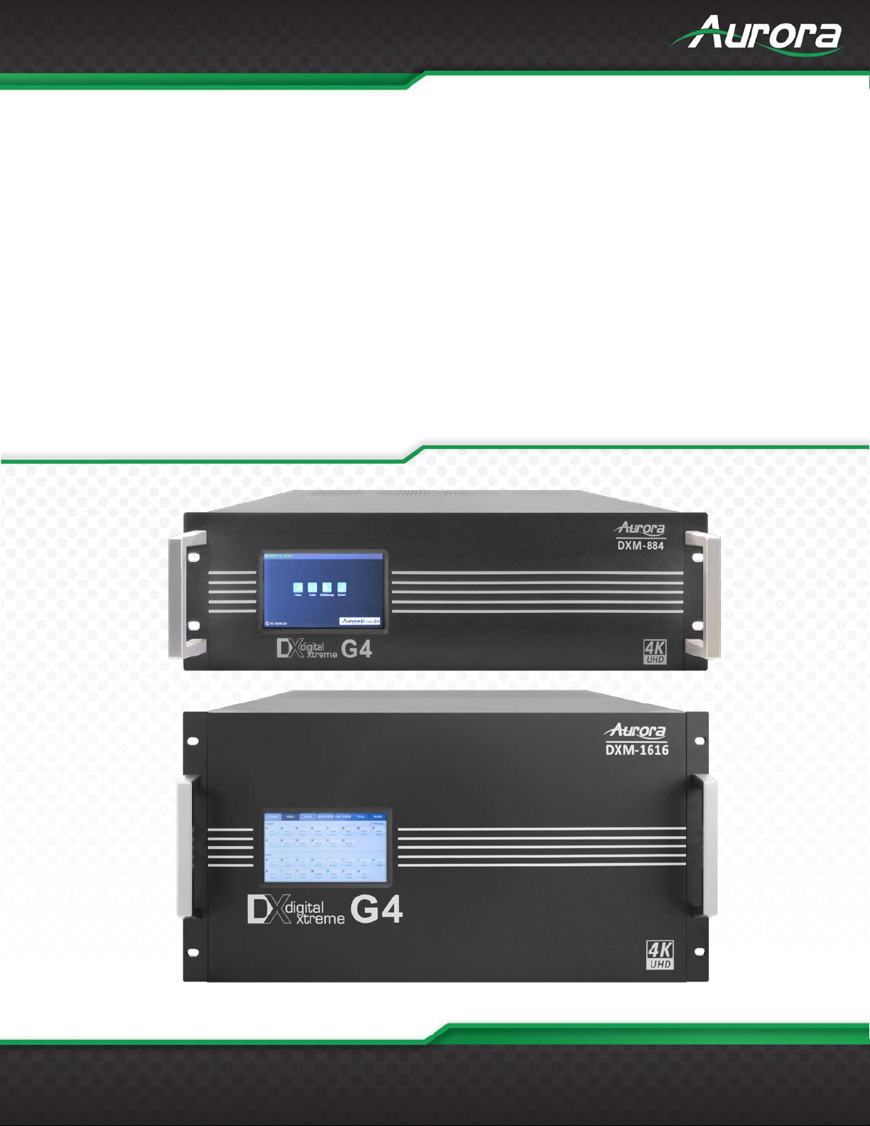
DXM-884 Front
LCD
5” color touch screen for routing and setup.
12
USERS GUIDE
www.auroramm.com
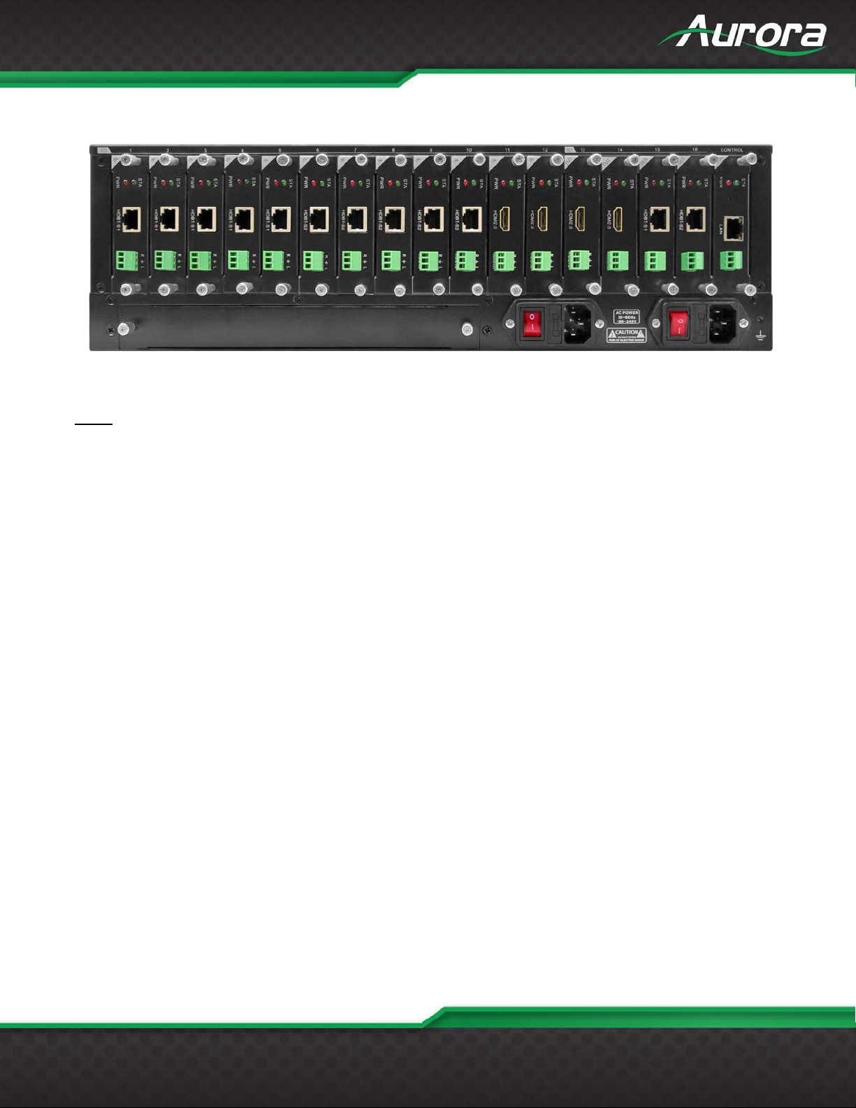
DXM-884 Rear
Rear
8 input only slots
4 input/output slots
4 output only slots
1 control card slot with 10/100 LAN and RS-232 port
2 IEC power connectors for redundant power.
1 Expansion slot for additional control ports and future capabilities.

13
USERS GUIDE
www.auroramm.com
DXM-1616 Front
LCD
5” color touch screen for routing and setup.
14
USERS GUIDE
www.auroramm.com
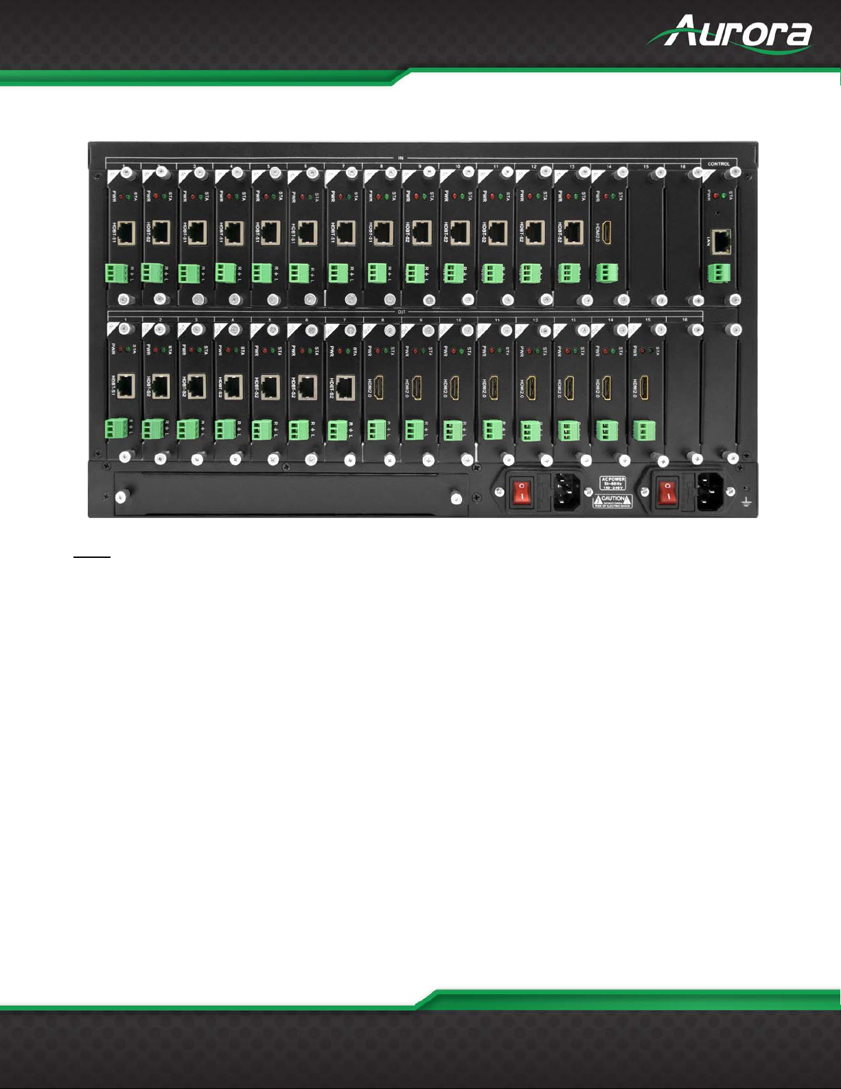
DXM-1616 Rear
Rear
16 input only slots
16 output only slots
1 control card slot with 10/100 LAN and RS-232 port
2 IEC power connectors for redundant power.
1 Expansion slot for additional control ports and future capabilities.

15
USERS GUIDE
www.auroramm.com
1 channel RS232 port
1 channel LAN port
Supports WEB based management
CARD FUNCTIONALITY
Main Control Card
The main control card comes with the DXM unit and allows the control of the unit via LAN or
RS-232.
LED’s:
STA (Status): Green if signal is active
PWR (Power): Red if board is working accordingly
Technical parameters
Type Specification
RS232
LAN
Can control the matrix by the commands
Controls and firmware updates via TCP/IP
16
USERS GUIDE
www.auroramm.com
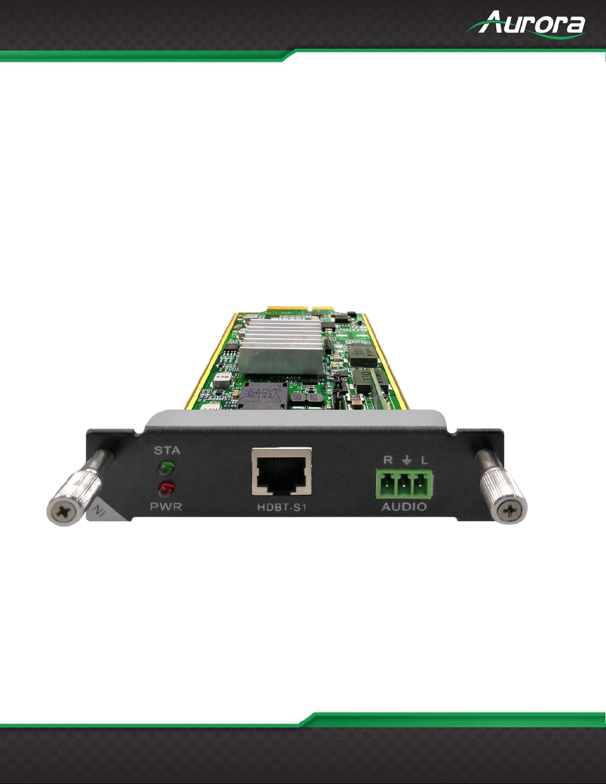
HDBaseT Cards
HDBaseT input and output cards are designed to receive or transmit audio, video, control, and
power up to 70m with 24bit 4K30Hz/4K60 4:2:0 depending on model using a single common CAT
5e / 6 / 6A cable. DXCI-1-HDBT1 & DXCO-1-HDBT1 will go up to 230ft with 36 bi t color dep th.
DXCI-1HDBT2 & DXCO-1-HDBT2 will go up to 328ft 48-bit color depth or 600ft with 24bit color
depth (CAT 6A shielded cable required for this distance). The output card has the unique ability to
auto detect a DVI display or device connected and automatically remove the audio from the signal
even if the source is HDMI. This saves space and cost as an external device to strip the audio
electrically i s not r eq ui red. The need to learn a DVI EDID is not requ i r ed with the DXM series due to
this feature. Both the input and output card have the ability to audio de-embed and allow stereo
output via the 3 pin Eu r o connector.
DXCI-1-HDBT1-G4 / DXCI-1-HDBT2-G4
17
USERS GUIDE
www.auroramm.com
Recommend the cable
type
1080P Maximum
transmission distance
4KMaximum
transmission distance
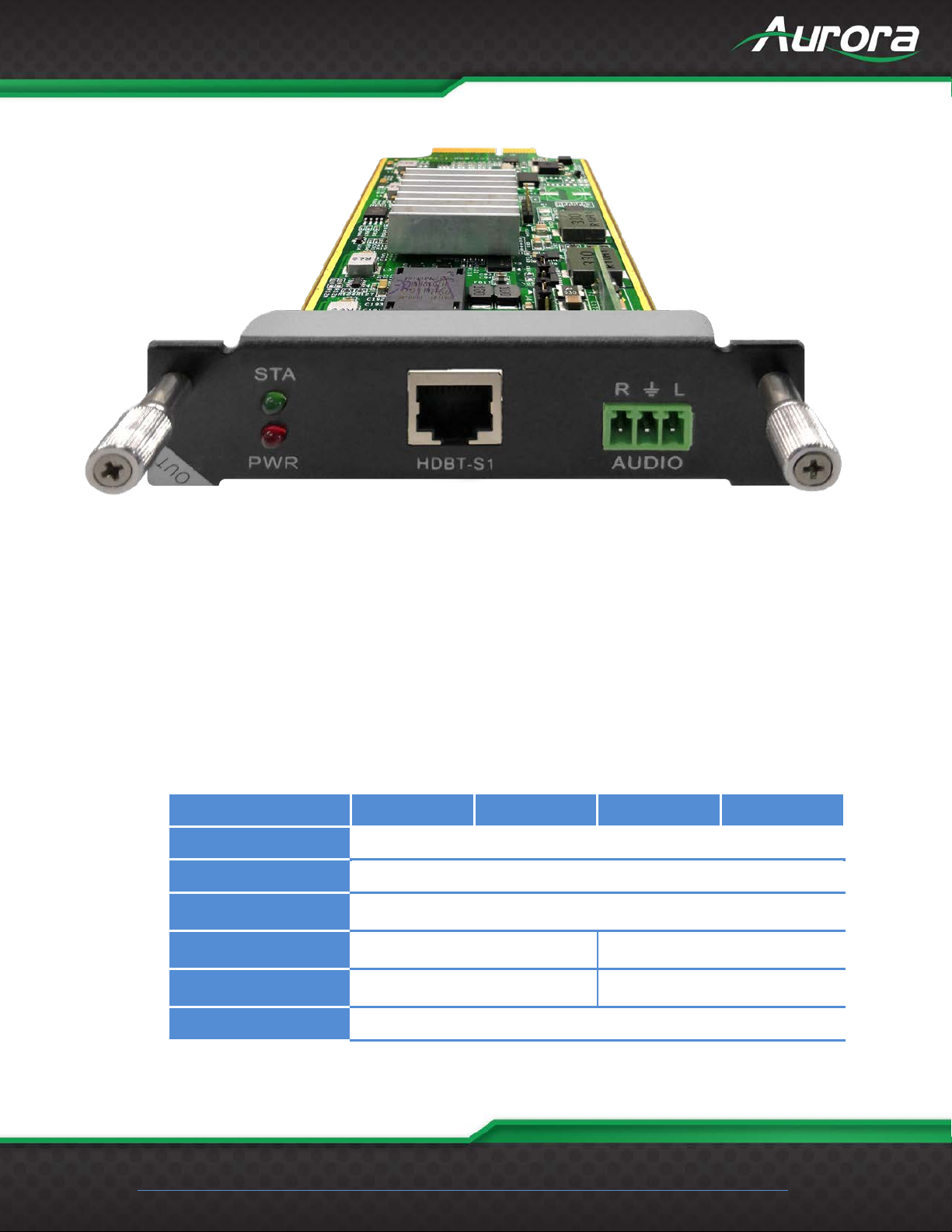
DXCO-1-HDBT1-G4 / DXCO-1-HDBT2-G4
LED’s:
STA (Status): Green if signal is active
PWR (Power): Red if board electricity works accordingly
Technical parameters
The board type HDBT1 input HDBT2 input HDBT1 output HDBT2 output
number/Signal types A HDBaseT audio and video signals and control signals
The connector type RJ-45 8P line terminal
≤ 70m ≤ 100m
STP CAT6/CAT6A and above
≤ 30m(CAT6A)
Support video standard
HDTV 1080p @60Hz;VESA 1920×1200;4K30Hz
≤ 60m(CAT6A)

18
USERS GUIDE
www.auroramm.com
Board type
HDBT1 input
HDBT2 input
HDBT1 output
HDBT2 output
Storage
temperature/humidity
Work
temperature/humidity
Support color space
Seamless switching No support
EDID management DDC channels, EDID manager
HDCP Management Settings HDCP authorization or not
Audio embedded embedded De-embedded
Port hot plug support
Power supply Single channel transceiver power supply DC +28V
Note Support RS232 pass through, terminal blocks, more flow
RGB;YCbCr(4:2:2) YCbCr(4:4:4)
-20℃ ~ 85℃/ 5%~40% RH
0℃ ~ 50℃/ 10%~70% RH
The matrix's HDBT modules (PoC) can supply power to connected HDBT modules. Plug in the jumpers J4 / J5:
PoE (right, prepared but not yet available) or PoC (left, see illustration). Remove the jumpers when connected
HDBT modules have their own power supply.
 Loading...