

Aurora Archer IS100, Archer IS200, Archer FSP100, Archer FSC100, Archer FS100 Installation & Operating Instructions Manual

Effective January 2003
INSTALLATION
&
OPERATING
INSTRUCTIONS
Serial Number: B.D. Number:
The Australian
Gas Association
Approval No. 4553/AG103
Australian Patent
PN 200110001S
Model: IS100
Model: IS200
Model: FSP100
Model: FS100
PLEASE KEEP THESE
INSTRUCTIONS FOR
FUTURE REFERENCE
Model: FSC100
Aurora
CLIMATE SYSTEMS
A.B.N. 43 108 083 987

TABLE OF CONTENTS
SAFETY LABEL
Warranty Installation Service 2
Safety Labels 3-4
INSTALLATION INSTRUCTIONS
Specifications 5-6-7-8
General Safety Information 9
Clearances to Combustibles 10
Log Installation 11-12-13
Fluing Requirements 14
Fluing Options / Installation 15-26
Optional Remote Control Thermostat 27-28
Gas Connection 29
Gas Valve Adjustment 30
Wiring Diagram 31
Safety Screen Installation 32
Insert Surround 33
Optional Pedestal Assembly 34
OPERATING INSTRUCTIONS
Automatic Humidifier Operation 35
Operating Instructions Checklist 36-37
Lighting Instructions 38
Fan Operation 39
Shutdown Instructions 39
High Temperature Cut Out 40
Paint Curing - First Firing 40
Operating Faults 41
Resetting the Heater 41
MAINTENANCE
Maintenance Instructions 42
Log Replacement 42
Main Convection Fan 42
Heat Exchanger 42
Gold/Chrome Plated Doors 43
Glass Replacement/Cleaning 43
SPECIFICATIONS
Automatic Flame Safeguard System 44
COMPLETE UNIT WARRANTY 45-47
1

TO THE NEW OWNER
Congratulations! You are the owner of a state of the art Archer High Efficiency Gas Log Space Heater.
This appliance has been designed to provide you with all the warmth and charm of a wood fire at the flick of a
switch. The Archer Gas Log Space Heater promises to provide you with the highest economy, heat output, comfort
and security.
NOTE: AURORA WARRANTY PROGRAM
Please note to qualify for the Aurora Warranty Program, you need to fill out the warranty registration form, and have
your qualified installer fill out the Installation Commissioning Report. Both documents must be returned promptly to
Aurora Climate Systems.
Under new government legislation, you also need to obtain from your qualified installer, a Certificate of Compliance
for the guarantee of the installation.
Please note, that Aurora Climate Systems will not accept responsibility for faults with the appliance caused through
installation faults. We therefore strongly recommend that you return to Aurora Climate Systems the Installation
Commissioning Report and obtain a Certificate of Compliance from your qualified installer for your protection.
Failure to do so can void your warranty.
Please take a moment now to acquaint yourself with the instructions and many features of your Archer High
Efficiency Gas Log Space Heater.
Warranty - Installation - Service
(Listing and Code Approvals)
This appliance has been tested in accordance with the Australian Gas Association AGA103 Test Approval No.
5445/1996, and has been certified to the Electrical AS.3100 standard.
Check with your local council’s building department to ensure compliance with local codes, including the need for
permits and follow up inspections. Or if you wish clarification of the instructions contained in this manual, please
contact Aurora Climate Systems on telephone (03) 9795 8895 or facsimile (03) 9701 2088.
Note: As the Archer Gas Log Space Heater you have purchased is a high tech, high efficiency
appliance, we wish to advise that your appliance should at all times only be installed by a licensed Gas
Fitter / Installer for the installation and service of the Archer Gas Log Space Heater.
At no time should this appliance be installed outside the installation guide lines contained in the
Installation Manual, or by a non qualified gas fitter / installer. To do so will void the warranty.
It is policy of Aurora Climate Systems that should a fault develop in the Archer Gas Log Space Heater during
its warranty period, Aurora will repair the appliance in these circumstances. However we wish to advise that
should the Archer Gas Log Space Heater develop a fault in its operation because the product was not installed
in accordance with the manufacturer’s guidelines and instructions, or if the product was not installed
correctly by a licensed gas fitter / installer or lack of operating knowledge of the appliance by the customer
causing appliance failure, then a service charge will apply.
In such cases, where attendance is required by Aurora Service Personnel to correct faults in the product which
are not directly related to the product and / or parts failure but are the result of improper installation and lack
of operating knowledge of the appliance, Aurora Climate Systems will charge the purchaser of the
appliance and the installer / service agent a fee calculated on the basis of $80.00 + GST per hour minimum, as
well as travelling expenses in excess of 25 km each way to rectify such faults.
Note: The Complete Unit Warranty, inclusions, exclusions, terms and conditions are listed on pages 49 to 51 of this
manual.
2
PLEASE KEEP THESE INSTRUCTIONS FOR FUTURE
REFERENCE
!
ADJUSTMENT, ALTERATION, SERVICE OR
MAINTENANCE CAN CAUSE INJURY OR
PROPERTY DAMAGE. REFER TO THIS
MANUAL FOR ASSISTANCE OR
ADDITIONAL INFORMATION, CONTACT
AURORA CLMATE SYSTEMS.
TELEPHONE NUMBER (03) 9795 8895
THIS APPLIANCE MUST BE INSTALLED OR
SERVICED ONLY BY A LICENCED GAS
FITTER FOR THE INSTALLATION AND/OR
SERVICE OF THE ARCHER GAS LOG SPACE
HEATER.
Note: If this appliance is installed by a licensed gas fitter who is not familiar on the
installation of the heater, we recommend that prior to installing the appliance the
installer contact Aurora to obtain further advice on the installation of the product.
IMPROPER INSTALLATION,
FOR YOUR SAFETY
What to do if you smell gas?
1) Open Windows
2) Turn off main gas supply
3) Do not touch any electrical switches
4) Extinguish any open flames
5) Immediately call your gas supplier
or installer
Do not store or use gasoline or other
flammable vapours and liquids in the
vicinity of this or any other appliance
3

SAFETY LABELS
Model - Archer Manufactured by Ο Ο
Gas Type
Model Type
Gas Consumption
Manifold Pressure
Injector Size - Front
- Rear
A.G.A Approval No
to Code AG103
Electrical conforms to AS3100 240V 50 Hz 80 Watts Max
Serial No:
Air Pressure switch
Cut in Pressure
Cut out Pressure
Electrical Connection
Natural
FS100 Ο
FSP101 Ο
IS102 Ο
30MjHr
0.8Kpa
1.6mm
2.4mm
5446
LPG
FS100 Ο
FSP101 Ο
IS102 Ο
30MjHr
1.5Kpa
1.1mm
1.5mm
5446
Date of Manufacture:
Cleveland Controls / RSS-495-226
65 Pa
50 Pa
2 Mtr flex standard 3 Pin Plug
Aurora Climate Systems
A.B.N. 43 108 083 987
71 - 73 Overseas Drive
Noble Park VIC 3174
To be installed by an authorised person in
accordance with installation instructions
provided with appliance.
Note: In case of power cord damage, replace only with Archer special cord set, obtainable from your Archer
Dealer or direct from Aurora Climate Systems.
!
DO NOT OPERATE THIS APPLIANCE BEFORE READING THE
INSTRUCTION BOOKLET
DO NOT PLACE ARTICLES ON OR AGAINST THIS APPLIANCE
DO NOT STORE CHEMICALS OR FLAMMABLE MATERIALS OR
SPRAY AEROSOLS NEAR THIS APPLIANCE
DO NOT OPERATE WITH PANELS, COVERS OR GUARDS
REMOVED FROM THIS APPLIANCE
DO NOT ENCLOSE THIS APPLIANCE
THE GUARD IS FITTED TO THIS APPLIANCE TO REDUCE THE
RISK OF FIRE OR INJURY FROM BURNS AND NO PART OF IT
SHOULD BE PERMANENTLY REMOVED
FOR PROTECTION OF YOUNG CHILDREN OR THE INFIRM, A
SECONDARY GUARD IS REQUIRED
4

SPECIFICATIONS - MODEL NO. FS101/P200
Heater with Pedestal and Single Flue Adaptor
157
23
1 Flue Outlet 40mm ø Pipe
2 Air Inlet
3 Electric Cord
4 1/2 “ BSP Connection (Inside)
5 Single Flue Adaptor
45
716
443
317
1
2
4
3
409
323
283
SPECIFICATIONS - MODEL NO. FSC100
Console Heater and Co-Axial Flue Adaptor
858
220
C/L Flue
317
697
1 Flue Outlet (Outside 65mm Inside 40mm)
2 Air Inlet
3 Electric Cord
4 1/2 “ BSP Connection (Inside)
5 Air Inlet Cover Plate
5
435
317
1
157
3
23
2
4
283
323
402
858
5
716
792
30
443
5
C/L Flue
317
483

SPECIFICATIONS - MODEL NO. FS100
Heater without Pedestal
716
638
1 Flue Outlet
2 Air Inlet
3 Electric Cord
4 1/2 “ BSP Connection (Inside)
443
97
706
C/L Flue
97
430
157
23
2
1
4
189
3
103
63
6

25
257
SPECIFICATIONS - MODEL NO. IS100
Fireplace Insert with Mantel surround IS001 (1100 x 858) with standard top panel.
1 Single Flexi Flue Starter Kit
2 Electric Cord
3 1/2” BSP Connection (Inside)
4 Surround (1100 x 858)
706
SINGLE FLUE
157
C/L Flue
MANIFOLD STARTER
40MM PVC
161
40MM
COUPLING
25
161
257
608
1
706
2
157
23
3
63
PVC FLEXIBLE
PIPE
4
97
103
90º/40MM
PVC ELBOW
858
608
638
150
1100
250
608
7
706

SPECIFICATIONS - MODEL NO. IS200
Fireplace Insert with Mantel surround IS002 (900 x 758) with cut-back top panel.
1 Co-Axial Manifold Flue Starter 65mm
2 Electric Cord
3 1/2” BSP Connection (Inside)
4 Surround (900 x 758)
5 Air Inlet Cover Plate
706
INTERNAL PIPE
40MM PVC
25
128
157
C/L Flue
CO-AXIAL FLUE
MANIFOLD STARTER
65MM PVC
290
C/L Flue
4
608
25
30
128
290
5
638
97
608
1
706
2
157
23
3
63
103
900
150
97
758
608
706
8
INSTALLATION INSTRUCTIONS
GENERAL SAFETY INFORMATION
1. This installation must conform with local codes or, in the absence of local codes, with AG 601
2. Provide adequate clearances around the product for servicing and ensure there are no obstructions to the combustion
air intake situated at the back of the heater. (Refer Page 6 item 2)
3. The appliance must be installed on a flat, solid continuous
or uneven surfaces can cause vibration or humming in the heater.
4. The Archer Gas Log Space Heater can be installed in a wide variety of ways and will fit nearly any room layout. It
may be installed in a recessed position, framed out into the room, or across a corner. For installation options refer
pages 18 through to 26.
5. This appliance (Insert and Freestanding Console Models) needs to be installed in such a way that the heater can be
removed
Note: Under no circumstances should the appliance be installed under conditions, which would not allow
for easy removal of the appliance to carry out routine inspection and service to the appliance, to do
so will void the warranty.
Note: On Single Wall flue pipe installations (imitation zero clearance fireplace) a minimum of 25mm clearance must be
provided at the rear of the heater to enable the heater to get sufficient combustion air to the air inlet located at the
rear of heater. (Refer installation instructions page 6 item 2).
Note: Where a mantel surround is being used on insert installations and imitation zero clearance fireplace
installations, the combustion air intake slot located in the top mantel surround must have no obstructions to allow
combustion air to enter through the slot to the combustion air inlet located at the back of the heater.
at all times to service the heat exchanger and flue fan located in the rear section of the heater.
IN CASES WHERE THE INSTALLATION OF THE HEATER IS
NOT IN ACCORDANCE WITH THE MANUFACTURERS
INSTRUCTIONS AND THE APPLIANCE CAN NOT BE
REMOVED FOR SERVICING IN SUCH CASES WHERE
!
SERVICE PERSONAL HAVE TO SPEND TIME TO REMOVE
THE HEATER OR CORRECT THE INSTALLATION A
SERVICE CHARGE WILL BE APPLICABLE TO THE
CUSTOMER OF LABOUR AT $80 PER HOUR PLUS GST PLUS
TRAVELING EXPENSES.
surface (ie. wood, metal, concrete). Please Note: Rough
!
!
!
!
THIS APPLIANCE SHOULD BE INSTALLED BY A QUALIFIED
LICENSED GAS FITTER.
DUE TO HIGH TEMPERATURES, THE APPLIANCE SHOULD
BE LOCATED OUT OF TRAFFIC AND AWAY FROM
FURNITURE AND DRAPERIES.
THIS APPLIANCE CAN ONLY BE FLUED IN
ACCORDANCE WITH THE MANUFACTURER’S
INSTRUCTIONS AS TESTED TO AGA CODE 601.
FAILURE TO INSTALL THIS APPLIANCE CORRECTLY MAY
CAUSE A SERIOUS HOUSE FIRE.
9
INSTALLATION INSTRUCTIONS
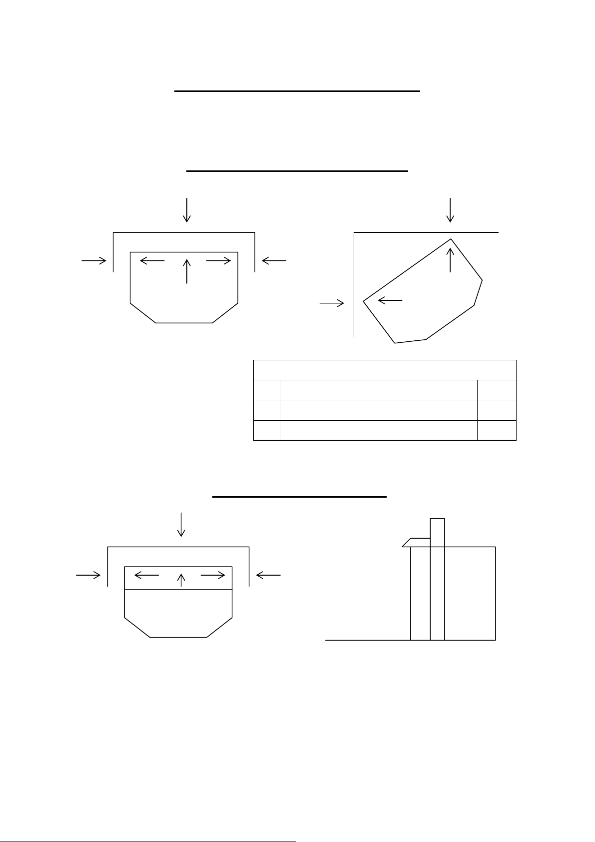
CLEARANCE TO COMBUSTIBLES
Freestanding models FS100 - FSP101
A
B B
C
Freestanding Units
A Rear Wall to Unit 25mm
B Side Wall to Unit 15mm
C Corner Installation 0mm
C
Fireplace Insert Model IS100
A
B B
Zero clearance
No hearth required
Note: The Archer Gas Log Space Heater has been tested and approved for zero
clearance to combustible materials. Aurora Climate Systems recommends that
clearances as listed above should be maintained to allow for removal of the
product for servicing.
For clearances required for Flue Connections refer Pages 17-21-25.
10

INSTALLATION INSTRUCTIONS
LOG INSTALLATION
The gas log set (front/middle log and rear log) is pre-set and installed in the factory. Only the
left and right hand cross logs are packaged separately inside the firebox for installation by
the installer.
1. To access the log set parcel, lift off top panel and remove the 2 screws in the left hand
and right hand side front panel on the top, which hold the left hand and right hand side
front panel.
2. Remove panels by lifting panel out and up, place panels in a secure position to avoid
damage to paint work.
3. Unlatch main door latches located on right hand side of the heater, open door fully.
Carefully remove right hand and left hand cross logs from firebox and remove
cardboard protection from middle logs, and all packaging materials.
Note: Position of rear log and front / middle log has been preset at factory and their
locations should not be changed. Check that logs have not been damaged in transit.
4. Carefully remove wrapping from right hand and left hand cross logs.
WARNING
5. Prior to positioning of left hand and right hand cross logs inspect front and rear burner
for particle or dust placement on top of burners. If any particles or dust is visible on
top of front or rear burners remove particles before placing cross logs into position.
Note: Ceramic logs are fragile and so to are the hot surface igniters underneath them
and need to be handled with care at all times.
6. Position left top cross log No (4) in locating slot of front / middle log No (2) and rear
log No (1) (Refer Diagram page 12-13).
7. Position right top cross log No (3) in locating slot of front / middle log No (2) and rear
log No (1) (Refer Diagram page 12-13).
8. After left hand and right hand cross logs have been placed in position and safety check
has been carried out, close main door and latch securely with latches located on right
hand side of heater. Please note: the door may need to be lifted slightly on the right
hand bottom corner when closing so that it sits level.
9. Refit left hand and right hand side front panels with 2 self-tapping screws, and refit the
top panel.
Front and rear burner inspection.
!
11
INSTALLATION INSTRUCTIONS
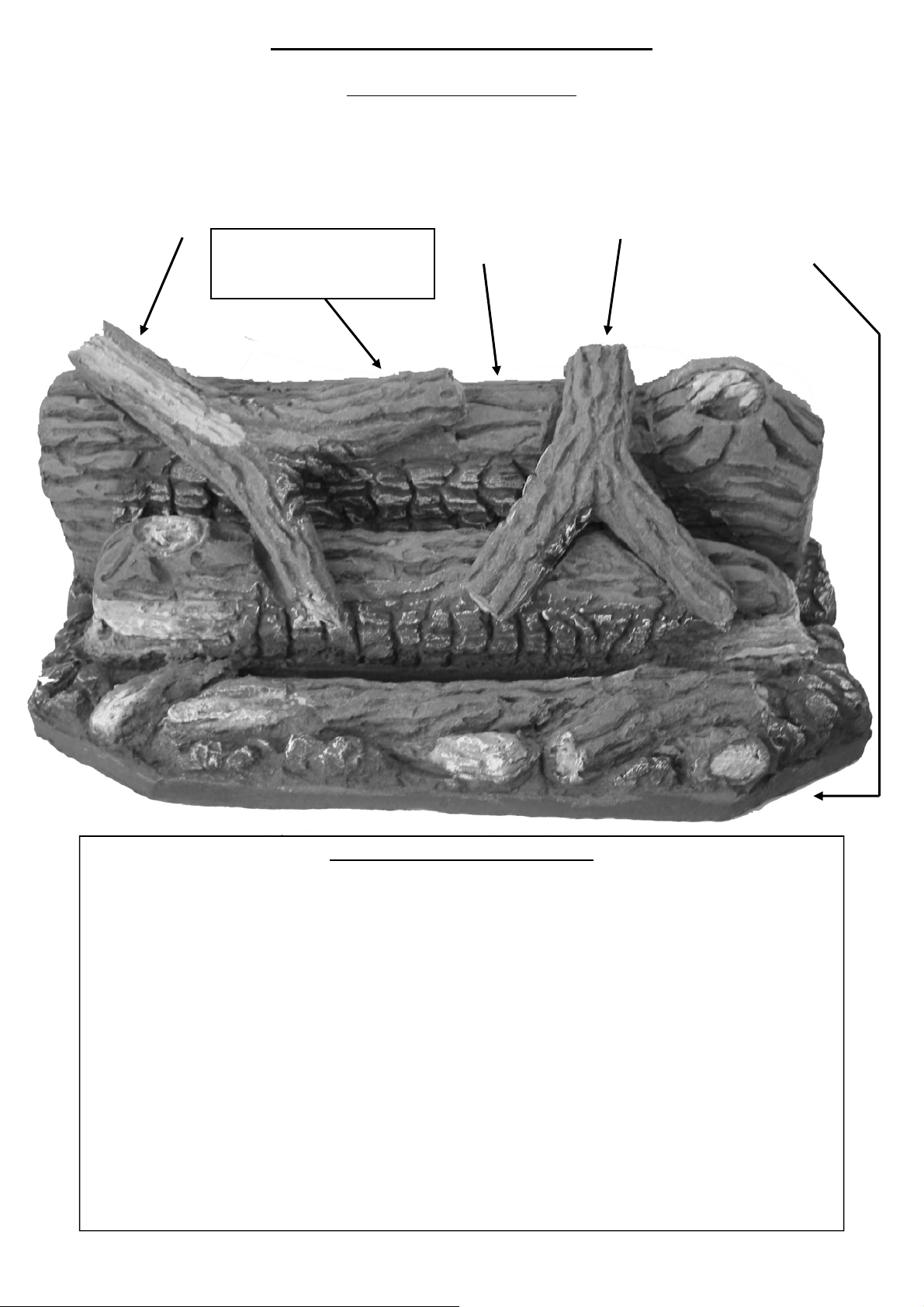
LOG SET DIAGRAM - A
The Gas Log Kit contains the following: 1) Rear Log
2) Front/Middle Log
3) R/H Cross Log
4) L/H Cross Log
4
Note: Location Pin has been
fitted to Rear Log (1) to hold
L/H Cross Log (4) in position.
1
3
2
INSTALLERS - PLEASE NOTE
(A) LOG SETTINGS
Do not remove logs from heater unless absolutely necessary!! Logs have been preset and aligned for
correct performance. Only place cross logs in position as per instructions above.
Please Note: Accurate placement of logs is critical for correct performance of heater.
(B) GAS PRESSURE FOR LPG
Do not adjust gas burner pressure on LPG. Gas burner pressure has been set at factory to required
gas burner settings for LPG.
(C) GAS PRESSURE FOR NATURAL GAS
For Natural Gas please check and adjust gas burner pressure if required as inline pressure can vary in
areas of Australia. For Natural Gas burner pressure settings refer to Page 4.
(D) ADJUSTMENTS
This product has been fully tested for its operation sequences and performance at the factory and no
adjustments should be made, except for the above mention of Natural Gas, to the appliance unless
approved by the manufacturer.
12
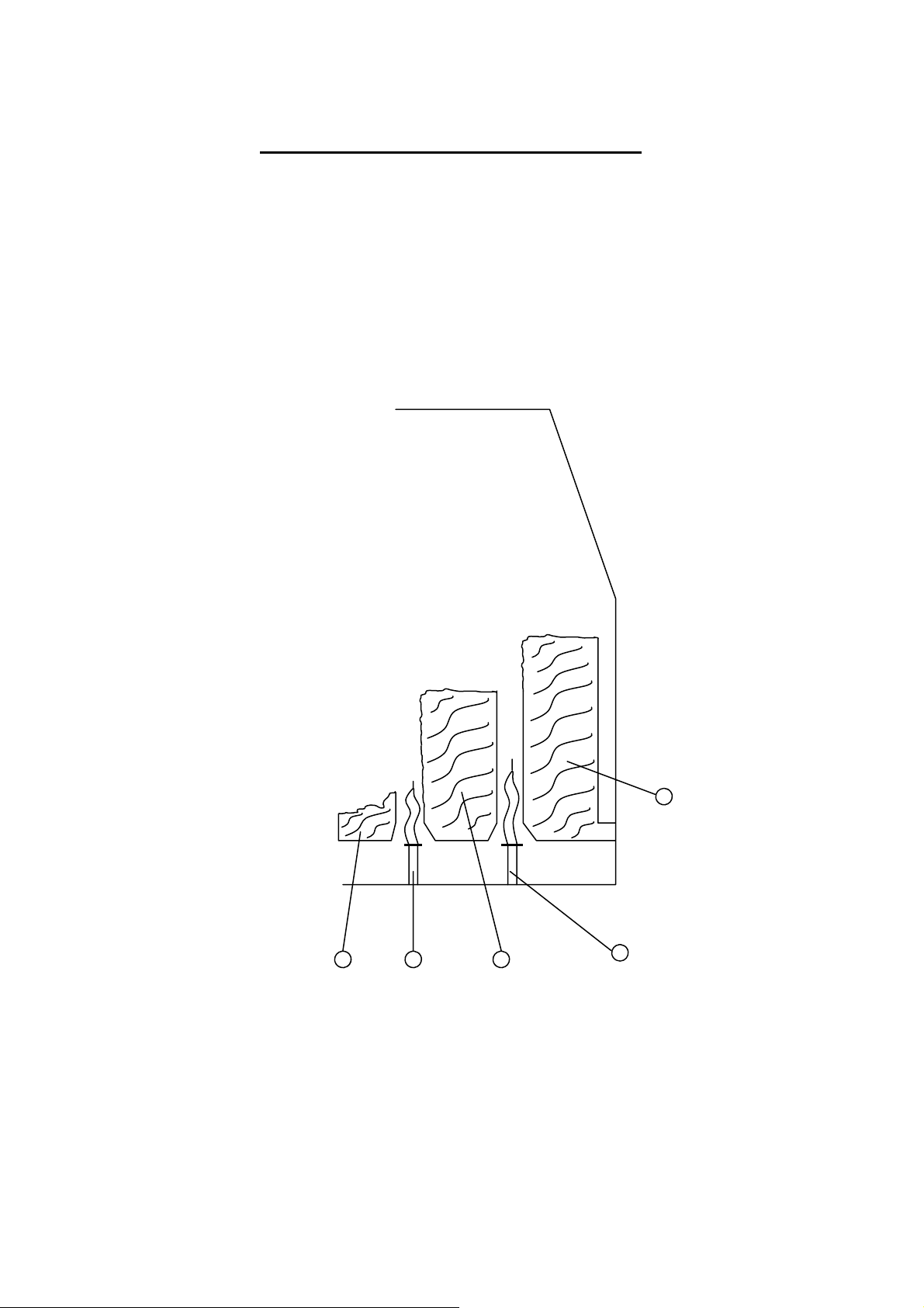
INSTALLATION INSTRUCTIONS
(Side view main logs and burners)
1. Rear Log
2. Front/Middle Log
3. Rear Burner
4. Front Burner
1
2 4 2
NOTE: Do not change position of rear logs and front/middle logs as their positions have been
present at the factory. Changing log positions will result in faulty gas burner function.
13
3

INSTALLATION INSTRUCTIONS
FLUING REQUIREMENTS
Co-Axial Flue Installations
Note: This appliance has only been approved for co-axial flue application if the flue (as
supplied by the manufacturer) is installed to an external wall or external fireplace.
(Refer installation diagram for Co-Axial Flue Installations Pages 16-17-18-19-24).
Single Flue Pipe/ Single Flexi Installations
Note: This appliance has only been approved for single flue pipe installation if the unit and
flue pipe is installed in line with the manufacturer’s installation instructions (Refer
installation diagram for single flue pipe installations Pages 16-20-21-22-23-24-25-26.
CONFIGURATION 1: Freestanding Models Pages 15-20-22-23 - Single Flue Application.
SINGLE PIPE 40mm ø 5.1 METRES HIGH WITH 2 x 45° ELBOW.
1 x 90° ELBOW AND ONE 75mm COWL.
CONFIGURATION 2: Insert Models Page 24-25-26 - Single Flexi Flue Application.
SINGLE PIPE 40mm ø 5.1 METRES HIGH INCLUDING 2 X 45°
ELBOW, 1 X 90° ELBOW, 1m FLEXIBLE PVC SECTION AND
ONE 75mm COWL.
CONFIGURATION 3: Freestanding and Insert Models for Installation on External Walls or
External Fireplaces Pages 16-17-18-19-24.
CO-AXIAL FLUE INTERNAL PIPE 40MM ø EXTERNAL PIPE
65MM ø BOTH PIPES IN PVC UP TO 1 METRE LENGTH FOR
WALL PENETRATION.
14
 Loading...