


Aurora Portable Generator
Operation Manual
Models AGI6500DE & AGI6500SDE

AGI6500DE & AGI6500SDE Operator / Owners Manual Version 11.4.1
INTRODUCTION
Customer satisfaction is very important to us. If at anytime you have any questions
about this manual or require further help we encourage you to contact us by visiting our
website at www.AuroraGenerators.com and using our LIVE CHAT, sending an e-mail to
Support@AuroraGenerators.com or call us Toll Free at 1-877-510-6807
This manual is updated on a regular basis. Insure you have the latest version by
downloading it from Aurora Generators website.
Read all instructions and warnings before using this product.
This manual provides important information on proper operation & maintenance. Every
effort has been made to ensure the accuracy of this manual. These instructions are not
meant to cover every possible condition and situation that may occur. We reserve the
right to change this product and instructions at any time without prior-notice. The
information contained within this document is updated regularly on our website.
If there are any safety concerns, do not operate this product.
Do not return this product to the retailer - Contact customer service
for service or assistance.
If you experience a problem, have questions or need parts for this product, call
customer service at 1-877-510-6807 A copy of your sales receipt maybe required.
This generator is intended for residential consumer use only.
This generator is intended for residential emergency standby use only. Air cooled
generators cannot be run full time and are not manufactured for commercial use.
Page 2

AGI6500DE & AGI6500SDE Operator / Owners Manual Version 11.4.1
SAFETY INFORMATION
(For safe operation please follow the instructions strictly)
Risk of fire and explosion
Never use gasoline in a diesel engine or fire and explosion may result.
•
Always handle fuel outdoors
•
Identify the correct fuel type and model before refueling.
•
Always wipe off any spilled fuel and oil before using your generator.
•
Keep generator away from any flammable products and at least 3 feet clearance
•
on every side.
Never use it in an enclosure
•
Refuel in a well-ventilated area with the engine stopped.
•
Do not fill the fuel tank above the upper limit line. Diesel fuel may expand during
•
operation.
Empty the fuel tank before storing or transporting this generator.
•
Before transporting, turn the fuel valve to the “OFF” position.
•
Acid warning
Be careful when using any battery
•
Batteries will exhaust hydrogen while charging.
•
Only charge a battery in a well ventilated place
•
Keep away from open flame, heat or spark
•
Avoid spilled battery acid. If contact with skin is made, wash immediately with
•
water.
Carbon monoxide warning
Carbon monoxide poisoning occurs after the inhalation of carbon monoxide gas. Carbon
monoxide (CO) is a product of combustion of organic matter under conditions of
restricted oxygen supply, which prevents complete oxidation to carbon dioxide (CO2).
Carbon monoxide is colorless, odorless, tasteless, and non-irritating, making it difficult
for people to detect.
Do not run the generator indoors, in confined spaces or in unventilated areas.
•
The carbon monoxide gas produced by gas and diesel engines can kill you.
•
Page 3

AGI6500DE & AGI6500SDE Operator / Owners Manual Version 11.4.1
Electrical Shock Warning
Electricity can kill you.
•
Installation should be preformed by a certified electrician. Improper installation can
•
result in electrical shock and death.
Follow all electrical safety code for your area. Consult an electrical safety inspector
•
or electrician.
Do NOT hook up any generator to a buildings electrical system without the proper
•
use and installation of a transfer switch installed by a qualified electrician.
Keep the generator dry.
•
To reduce the risk of electrical shock do not use it in the rain or snow. Your
•
generator should be protected from the elements
Do not allow children or non-qualified persons to operate this generator.
•
Operator Responsibility
Know how to stop the generator quickly in case of emergency
•
Understand the proper operation and maintenance procedure before using it
•
Be sure anyone using the generator receive proper instruction
•
Keep away from children and animals
•
Never run the generator unattended.
•
Connections to a building electrical system
Connections for standby power to a building's electrical system must be made by a
qualified electrician. The connection must isolate the generator power from utility power,
and must comply with all applicable laws and electrical codes. A CSA or UL approved
transfer switch is recommended. Improper connections to a building's electrical system
can allow electrical current from the generator to back feed into the utility lines. Such
back feed may electrocute utility company workers or others who contact the lines
during a power outage. When utility power is restored, the generator may explode, burn,
or cause fires in the building's electrical system. You are required to check local
regulations for proper registration, use and procedures for generators. The ground
terminal can be used to earth the generator or bond the frame of the generator to the
frame of a vehicle, but only if it is required by local law or electrical code. Before using
the ground terminal consult a qualified electrician or electrical inspector for regulations
in your area.
Generator ground circuits
Bonding the neutral wire to ground is required on some construction sites. Industrial
Generators provide neutral bonding. Some models are neutral bonded which allows the
industrial generator to pass Occupational Safety and Health Administration job site
Page 4

AGI6500DE & AGI6500SDE Operator / Owners Manual Version 11.4.1
inspections. Portable generators have a system ground that connects generator frame
components to the ground terminals in the AC output receptacles. The system ground
may or may not be connected to the AC neutral wire. This is called "neutral bonding"
Local regulations, codes or laws may require that the ground system be connected to
the AC neutral wire depending on its use. Most of our products have a "neutral bonded"
grounds.
AC Applications
Before connecting an appliance or power cord to the generator: Make sure that it is in
good working order. Faulty appliances or power cords can create a potential for
electrical shock. If an appliance begins to operate abnormally, becomes sluggish or
stops suddenly, turn it off immediately. Disconnect the appliance, and determine
whether the problem is the appliance, or if the rated load capacity of the generator has
been exceeded. Make sure that the electrical rating of the tool or appliance does not
exceed that of the generator. Never exceed the maximum power rating of the generator.
Power levels between rated and maximum may be used for no more than a few
minutes. Substantial overloading will open the circuit breaker. Exceeding the time limit
for maximum power operation or slightly overloading the generator may not switch the
circuit breaker OFF, but will shorten the service life of the generator. Do not exceed the
current limit specified for any one receptacle. If an overloaded circuit causes the AC
circuit breaker to switch OFF, reduce the electrical load on the circuit, wait a few
minutes and then reset the circuit breaker. An overloaded DC circuit, excessive current
draw by the battery, or a wiring problem will trip the DC circuit protector. It is either a
push button that extends out or is a physical fuse that will have to be replaced. If this
happens, wait a few minutes before pushing in the circuit protector to resume operation.
If the circuit protector continues to switch off or blow fuses, discontinue charging and
check your load. Empty batteries, or low batteries may overload the circuit.
DC Operation
The DC terminals on the front of the generator panel may ONLY be used for charging
12 volt automotive-type batteries. Do not start a vehicle while the battery charging
cables are connected and the generator is running. The vehicle or the generator may be
damaged. It is not a smart charger and can over charge batteries. Caution should be
used when charging any battery.
Aurora Generators use a charge controller / voltage regulator to maintain its down 12
volt battery for electric starting.
Page 5

AGI6500DE & AGI6500SDE Operator / Owners Manual Version 11.4.1
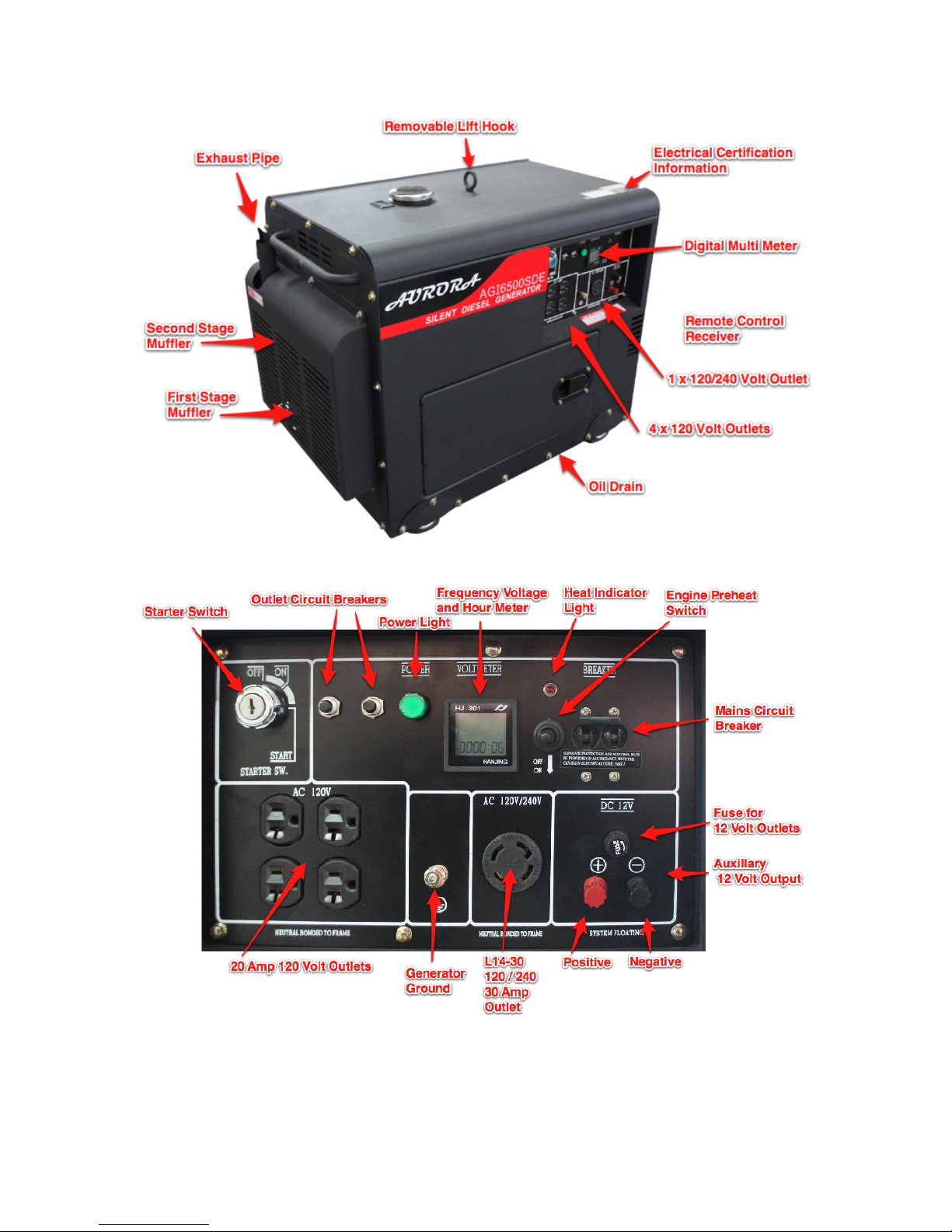
GENERATOR OVERVIEW
The main difference between the Aurora open frame generator and enclosed silenced
type is the noise it produces. Both models use the same engine and alternator with
some minor differences.
The enclosed silent diesel generator uses two much larger mufflers and a separate
diesel oxidation catalyst ( also known as a catalytic converter) The enclosed diesel
generator does not use a manual recoil starter. In place of the manual recoil starter is a
larger flywheel with fins used to force air through the enclosure, around the engine and
exhaust system to keep it running at normal temperatures. The enclosed silent type
generator runs much quieter and comes with a remote control to start and stop it.
Common Features
EPA Approved 11 HP Diesel 186F Type Single Cylinder Engine 3600 RPM
•
FCC Approved Remote Control Transmitter ( Silent Diesel Only )
•
ETL Certified to CSA Standard 22.2 No 100
•
Self Excited 2 Pole Singe Phase Alternator
•
12 volt, 120 and 240 volt output
•
User Adjustable Automatic Voltage Regulator
•
Electric Start (silent version includes remote control start)
•
Battery Included in both models
•
Automatic Low Oil Shut Down
•
Digital Hour, Voltage and Frequency Meter
•
Page 6
AGI6500DE & AGI6500SDE Operator / Owners Manual Version 11.4.1
Page 7

AGI6500DE & AGI6500SDE Operator / Owners Manual Version 11.4.1
Page 8

Technical Specifications
Technical Specifications
Generator Model
AGI6500DE & AGI6500SDE
Certifications
2011 / 2012 EPA
ETL Approved to CSA 22.2 No.100
Engine Model
Aurora 186F
Engine Type
Air cooled single cylinder, 4 stroke, direct injection diesel.
Cooling System
Forced air cooled
Engine Speed
3600 RPM ( 60 Hz )
3000 RPM ( 50 Hz )
Engine Displacement
418 cc
Engine Bore
86 x 72
Engine Power
11 H P
Engine Lube Oil
Synthetic 15W40 for diesel motors only.
Oil Lube Capacity
1.65 L
Engine Lube Oil Pump
Forced
Engine Run Time
12 Hours / 2.9 Gallons under 75% load
Cold Start Heater
Installed on air intake
Decompression Valve
Installed on engine
Fuel Type
Diesel Ultra Low Sulfur Automotive Fuel Only.
Max Height Above Sea Level
1000 Meters / 3280 feet
Generator Type
Self Excited two poll single phase
Voltage Regulator
User adjustable automatic voltage regulator
Generator Insulation
Class F
Power Factor
1
Rated Frequency
60 Hz.
Rated Output
120 Volts @ 41.6 amps
240 Volts @ 28.8 amps
AGI6500DE & AGI6500SDE Operator / Owners Manual Version 11.4.1
Page 9

AGI6500DE & AGI6500SDE Operator / Owners Manual Version 11.4.1
PRINCIPLES OF OPERATION
Fuel System
The Generator Fuel System provides filtered and pressurized diesel fuel to the diesel
engine. It consists of a fuel tank with removable fuel fill strainer, fuel lines, fuel filter, fuel
injection pump, and a fuel injector.
The diesel fuel is stored in a fuel tank. The tank features a plastic mesh strainer in the
fill neck opening and a fuel tank drain valve. The fuel tank supplies fuel via a flexible
tube to the fuel filter. The fuel filter removes impurities and water from the diesel fuel
before it reaches the diesel engine. The fuel filter is made up of a clear bowl and filter
head with a throw-away paper filter. The fuel filter also includes a fuel shutoff valve and
some version include bleed screws for removing air trapped in the fuel system. Another
flexible tube connects the fuel filter and the fuel injection pump (part of the diesel
engine).
With the engine cranking or running, the fuel flow is controlled by a mechanical
governor (part of the diesel engine) and the fuel injection pump. The fuel injection pump
pressurizes the fuel and transfers it to the fuel injector. Fuel is sprayed by the injector
into the engine combustion chamber where it is mixed with air and ignited. (This video
explains how it works) The fuel that is not burned by the engine is returned to the
generator set fuel tank via an excess fuel return line on the fuel injector. The returning
fuel is used to lubricate the injector and keep it cool. Any derbies in the fuel system may
cause the fuel injector to stick open or not close completely. This dripping of fuel will
result in poor combustion and engine operation.
The diesel engine is shutdown by the operator depressing the engine STOP lever which
places the fuel injection pump control rack in the no fuel position. Stop the fuel and you
stop the engine. For models that can be shut off by an electric switch, an electric
solenoid pulls a cable that releases the same RUN/STOP lever. The drawbacks are
that you have to reset this RUN/STOP lever back to the run position the next time you
want to use the generator.
Alternatively some models use an electric fuel switch to stop the fuel from reaching the
fuel pump. The switch is an electric magnet that pulls open a spring loaded plunger
with rubber stopper at the end of it. When open, the engine can run normally. When
closed it starves it of fuel causing it to shut down.
Low oil pressure detected or the engine starter switch turned to the off position can
trigger either one of these devices to shut down the engine starving it of fuel.
Some fuels can damage the rubber fuel stopper inside the electric fuel switch causing it
to stick and not open. Overheating or intermittent electrical connection may cause the
electric magnet release or fail resulting in a engine that will not start or is starved of
enough fuel that under load it fails to run correctly. This electric fuel switch is only
Page 10

AGI6500DE & AGI6500SDE Operator / Owners Manual Version 11.4.1
required for automatic engine starting and stopping. Removing the plunger inside will
defeat it and let you continue using your engine in the event of this component failure. If
this component fails immediate replacement is recommended in order for low oil
pressure auto safety shut down the engine and prevent further damage.
Engine Air Intake and Exhaust System
The Engine Air Intake and Exhaust System provides filtered air to the diesel engine and
an outlet for exhaust gas produced by air/diesel fuel combustion. The system consists
of an air intake filter, air intake manifold, exhaust manifold, and muffler system.
The air intake cleaner features a foam pre-filter and a disposable paper filter element.
Air is drawn through the pre-filter and the filter element. Airborne dirt is trapped in the
pre-filter and air intake filter element. Filtered air passes through the filter, air intake
manifold, and open intake valve into the engine combustion chamber where it mixes
with pressurized diesel fuel and is combusted.
Immediately following combustion, hot gases are forced out of the combustion chamber
(through the open exhaust valve), and into the exhaust manifold. The exhaust manifold
passes the gases into the muffler which deadens the sound created by the combustion
process. The gases then pass through diesel oxidation catalysts and the muffler system.
A muffler system can get very hot and personnel may occur if users inadvertently touch
the muffler while the diesel engine is running or before it has cooled down.
Engine Speed Control
Diesel engine speed is maintained by the speed control system which includes the
mechanical governor, governor lever, RUN lever, and STOP lever. The system is
designed to maintain engine speed under load at a constant rate of between 3570 and
3630 rpm (no load speed of 3750 rpm).
The governor is the flyweight-type, with the weights mounted on a gear driven by the
engine camshaft gear. The force of the flyweights is transferred through a thrust sleeve
and collar to the governor lever which is balanced against the tension of the governor
spring. The spring is stretched between the governor lever and the engine RUN lever.
When the engine speed drops below the governed speed, the resulting decrease in
governor flyweight / camshaft rotation places tension on the governor spring. The
tension repositions the fuel injection pump rack and increases the stroke of the plunger
in the fuel injection pump allowing more fuel to flow to the pump delivery valve. The
increase in fuel flow causes the diesel engine to speed up. As the diesel engine
recovers to the governed speed, the governor flyweight / camshaft rotation stabilizes
and the tension on the governor spring relaxes. This changes the position of the fuel
injection pump rack and shortens the stroke of the plunger allowing less fuel to flow to
the fuel injectors maintaining the engine speed at 3600.
Page 11

AGI6500DE & AGI6500SDE Operator / Owners Manual Version 11.4.1
The governor control mechanism features two operator controlled levers. The diesel
engine RUN lever places tension on a spring attached to the governor lever. The
tension places the governor lever in a position to allow fuel flow to the fuel injector for
diesel engine start up and to allow the diesel engine to continue running after start up.
The diesel engine shutdown or STOP lever is operated by either depressing the red
STOP lever or by the low oil pressure shutdown system. When depressed, the lever
trips the RUN lever releasing the tension on the governor spring which places the
governor lever in a no fuel or stop position. This action shuts off fuel flow to the fuel
injector stopping the combustion process and shutting down the diesel engine
Engine Electrical Starting System
The diesel engine electrical starting system can be used to start the diesel engine
whenever there is a 12 VDC power source connected. Aurora generators have a battery
included with the generator that may already be connected. When the generator is
running, it recharges the battery. Electrical Starting will be required when starting the
diesel engine in extremely cold weather or as a backup to the manual starting system
found on the open frame type generators. The electrical system also provides a means
for warming diesel engine intake air which also helps to start the engine in cold weather.
The system consists a momentary contact switch located on the generator electrical
panel.
Starting the engine with the starter motor is possible when the operator places the start
switch in the START position, power is applied through the switch to the starter
solenoid. This energizes the coil in solenoid which pulls in the solenoid's plunger and
pushes the starter drive pinion attached to the plunger toward the engine flywheel. This
movement engages the starter pinion drive with the ring gear teeth on the diesel engine
flywheel. As the solenoid plunger pulls in, the power available at solenoid pin S is
applied via a jumper to the starter motor which rotates the starter pinion drive (part of
the starter motor) and turns over the flywheel engaged with the pinion drive to start the
diesel engine. Immediately after the diesel engine starts, the generator set operator
releases the START switch. This opens the solenoid-starter circuit causing the solenoid
plunger to release the starter pinion drive disengaging it from the engine flywheel ring
gear. At the same time, the starter motor is de-energized. The starter pinion will return to
its normal position as the starter motor slows to a stop.
When your generator is running, the battery is automatically kept charged. A charge
regulator is mounted on the side of the engine and gets its power from the generator. A
dead battery or very low charged battery can overload and damage the built in charger.
Never use a low charged or dead battery.
Engine Pre-Heating
Preheat Circuit. The diesel engine features one 12-VDC resistance-type heater located
in the engine air intake piping between the intake manifold and the air cleaner. The
Page 12

AGI6500DE & AGI6500SDE Operator / Owners Manual Version 11.4.1
heater warms the air intake piping and manifold in order to warm up the intake air during
attempted cold weather starts. To use it, toggle the momentary switch located on the
front panel. Press down on it and hold it for up to 20 seconds. It will power the glow
plug to heat it up. Release it and start your generator normally.
De Compression Lever
The de-compression leaver is often used to aid in cold starting or when starting using
the manual recoil starter. Pressing the decompression leaver causes the exhaust valve
to be held open and prevents compression during the up stroke. Eliminating the
compression cycle helps the operator create enough inertia and engine speed that
when compression is restored starting should be much easier.
Generator Voltage Regulation
The generator voltage regulation and output supply system senses the load being
drawn at the load terminals and adjusts the alternator output accordingly. The system
also monitors and adjusts generator set performance and provides power to the
electrical terminals and receptacles.
The system consists of the AC alternator, voltage regulator, ON-OFF load circuit
breaker, output load terminals, AC Volt Meter, Hour Counter, Frequency HERTZ meter
and voltage adjustment potentiometer.
The generator set output voltage is controlled by the voltage regulator. The voltage
regulator continuously senses the alternator output voltage. The voltage regulator reacts
to voltage variations by manipulating the alternator field current to maintain the output
voltage. The field current controlled by the voltage regulator is supplied by the alternator
excitation windings. The voltage regulator performs this function using three interactive
sub circuits: power input, load sensing, and DC output. The power input circuit draws
current from the AC generator exciter windings through the positive (+) field brushes at
A1 pin 3. The load sensing circuit monitors the current being drawn by the load at A1 pin
E1. As demand increases, the DC output circuit draws current from the power input
circuit, rectifies it to direct current, and reapplies it to the AC alternator (G2) field via A1
pins F+ and F-.
Starting the diesel engine automatically field flashes the AC alternator (G2) with residual
magnetism stored in the rotor. The residual magnetism induces voltage in the power
excitation windings at AC alternator (G2) pins + and 2. As the diesel engine speed
begins to increase toward its governed no load speed of 3750 rpm, the induced voltage
in the power excitation windings increases. The voltage regulator (A1) power input
circuit receives current from the power excitation windings via the positive (+) field
brushes at A1 pin 3. Whenever the voltage in the load sensing circuit matches the set
point, the current entering the voltage regulator (A1) at pin 3 is allowed to pass through
the power input circuit. Whenever the voltage entering the sensing circuit is lower than
the set point (indicating a load increase) the DC output circuit reacts by drawing current
Page 13

AGI6500DE & AGI6500SDE Operator / Owners Manual Version 11.4.1
from the power input circuit. This current is rectified to DC and reapplied via A1 pins F+
and F- to the AC alternator rotor brushes at G2 pins + and -. The application of direct
current to the rotor increases the field magnetism between the AC alternator stator and
rotor which in turn, increases the current measured across the alternator power
windings. The current measured at both the excitation and power windings will increase
until the voltage entering the voltage regulator (A1) load sensing circuit matches the set
point at which point, the alternator output stabilizes and the A1 DC output circuit stops
drawing current from the power input
circuit.
The voltage regulator set point can be changed by adjusting the VOLTAGE ADJ.
potentiometer.
The generator set performance can be monitored by observing the AC VOLTS meter
and Hertz Frequency Meter. The VOLTS AC meter (M2) measures the voltage across
the power windings of the AC alternator and displays the value in VAC
from 0 to 300. The HERTZ frequency meter measures frequency across the power
windings in Hz from 45 to 65. The mains circuit breaker protects the VOLTS AC and
HERTZ frequency meters from a potential over current condition.
Low Oil Pressure Protection
The low oil pressure protection system shuts down the diesel engine in the event of low
oil pressure in order to protect the engine from further damage. The system consists of
a low oil pressure switch located in the engine block above the oil strainer, a low oil
pressure solenoid mounted in the control panel, and a cable connecting the low oil
pressure solenoid to the diesel engine STOP lever. The enclosed diesel generator does
not use a pressure solenoid, a electric fuel switch is use instead and is mounted on the
fuel pump.
Under normal operating conditions the low oil pressure sensor switch OPENS at 15 PSI
If a malfunction occurs in the lubrication system causing the oil pressure to drop below
the low oil pressure set point, the low oil pressure switch closes and completes a circuit
causing either the engine stop solenoid to release the engine STOP lever or if equipped,
closes shut the fuel valve located on the fuel pump. When this occurs the low oil
pressure light will illuminate on the generator control panel.
Page 14
 Loading...