

Page 1
AURO 2908
Barcode Scanner
Programming Reference Guide
Version 12
AURO 2908
AURO 2908
Automatic Recognition International Keyboard
16-Bit Microcontroller
Page 2

CONTENTS
About This Guide
Introduction
Notational Conventions
Service Information
AURO AIDC TEC Support Center
GENERALITY
Set Default Parameter
PREFIX / SUFFIX
Prefix / Suffix characters setting
INTER-CHARACTERTER DELAY
Beeper Tone
AIM IDENTIFIER
SCANNER MANAGMENT
Decode Timeout
TRANSMISSION
RS232 TRANSMISSION
Baud Rate
Parity
Data Bits
Stop Bit Select
XON/XOFF
Standard RTS\CTS
ENQ
ACK/NAK
RS232 TIMEOUT
WEDGE TRANSMISSION
SYMBOLOGY
Enable/Disable UPC-A/ UPC-E
MSI Check Character
En Enable/Disable MSI
UPC/EAN
CODE 39
CODABAR
2/5 ENTRELACE
2/5 STANDARD
2/5 MATRIX
Message Length
MSI
PLESSEY
Message Length
EAN 128
Appendix
ASCII TABLE
EXTENTED TABLE
DECIDE ZONE
2
2
3
3
4
5
5
5
5
6
7
7
7
8
9
9
11
12
12
12
13
13
14
15
16
17
18
18
19
19
20
22
23
25
26
27
27
28
29
29
30
31
32
33
33
1
Page 3
About This Guide
You have the option to program your scanner to perform various functions or activate
different features. This guide describes the features and provides the programming bar codes
necessary for selecting these features for your scanner.
The organization of this manual is intended to support a variety of users while making it quick
and easy to find the information you need.
Introduction
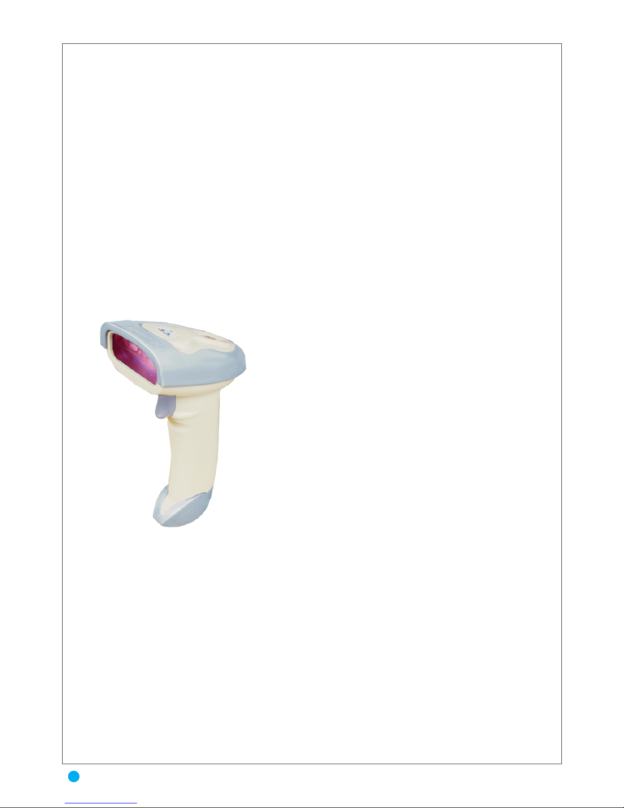
Auro 2908 combines excellent scanning performance and advanced ergonomics to provide
the best value in a lightweight laser scanner. Whether used as a hand-held scanner or in hands-free
mode in a stand, the scanner ensures comfort and ease of use for extended periods of time.
Auro 2908 accuracy captures data fast helping employees work quickly and efficientlly. This
enables the Auro 2908 to read damaged or poor printed barcodes, saving time, increase accuracy and
speeding throughput. It is easy to deploy and use plus the ergonomics, balanced from factor reduces
user fatigue to maximize user
Rugged environment demand rugged design with double molding ABS plastic andrubber.
The Auro 2908 delivers it with impact residence housing, integral shock mounting. These scanners are
lightweight and well balanced for your comfort. Scratch-resstant tempered glass helps preservebarcode scanning sccuracy.
The AURO AIDC TEC product focus is on best of class performance in warehousing transportation, health-care, retail solution and other industrial applications.
Auro 2908 Is Plug and Play scanner incorporates a multiinterface designwith Automatic Recognition international
keyboard. Universal cable compatibility. Delivery enhanced
productivity and efficiency while reducing your total cost
productivity. Power by microchips.
Auro 2908 handheld barcode scanner from AURO AIDC
TEC offers high performance scanning at a moderated
price. Auro 2908 singleline laser scanners provides fast and
agressive scanning of all standard 1D barcodes, reliable
scanning in a durable, lightweight form factor.
Auro 2908
2
About This Guide & Introduction
Page 4
Notational Conventions
The following conventions are used in this document:
• Bullets(•)indice:
• action items
• lists of alternatives
• lists of required steps that are not necessarily sequential
• Sequential lists (e.g., those that describe step-by-step procedures) appear as numbered lists.
• Throughout the programming bar code menus, asterisks (*) are used to denote default
parameter settings.
Service Information
If you have a problem with your equipment, contact the AURO AIDC TEC Support Center
for your region. See page xiv for contact information. Before calling, have the model number,
serial number, and several of your bar code AURO AIDC TECs at hand.
Call the Support Center from a phone near the scanning equipment so that the service person
can try to talk you through your problem. If the equipment is found to be working properly
and the problem is reading bar codes, the Support Center will request samples of your bar
codes for analysis at our plant.
If your problem cannot be solved over the phone, you may need to return your equipment for
servicing. If that is necessary, you will be given specific directions.
Note: AURO AIDC TEC Technologies is not responsible for any damages incurred during shipment
if the approved shipping container is not used. Shipping the units improperly can possibly void the
warranty. If the original shipping container was not kept, contact AURO AIDC TEC to have another
sent to you.
3
Notational Conventions & Service Information
* Indicates Default *Baud Rate 9600 Feature/Option
Page 5
AURO AIDC TEC Support Center
For service information, warranty information or technical assistance contact or call the
AURO AIDC TEC Support Center in:
Auro 2908
4
AURO AIDC TEC Support Center
Page 6
GENERALITY
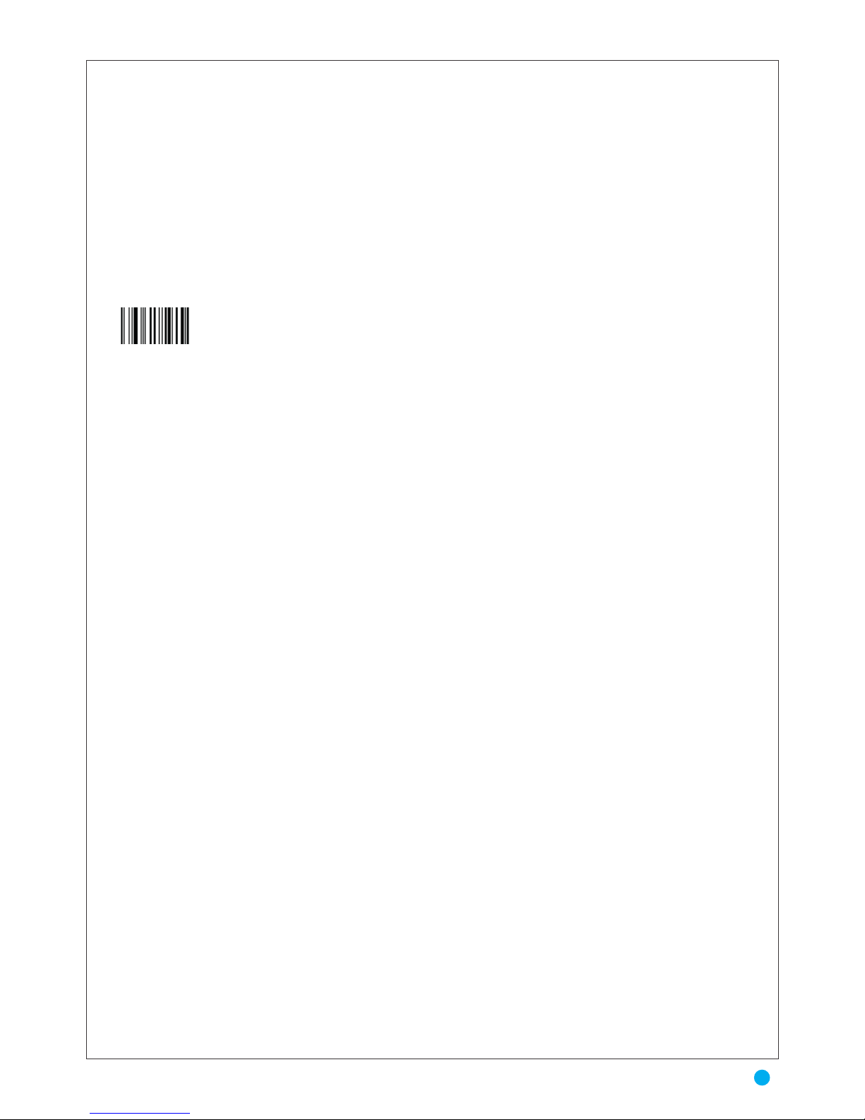
Set Default Parameter (factory setting)
When shipped from the factory each barcode scanner is configured with default parameter
values.
PREFIX / SUFFIX
Scan the appropriate bar code below to enable or disable adding the prefix character “A” to all
Code 32 bar codes.
A prefix/suffix may be appended to scan data for use in data editing. These values are set by
scanning a four-digit number (i.e., four bar codes) that corresponds to key codes for various
terminals. See the table for conversion information. Numeric bar codes begin in Appendix. If
you make an error or wish to change your selection, scan Cancel on BAR CODE SETTINGS.
When a barcode is scanned, additional information is sent to the host computer along with the
barcode data. This group of barcode data and additional, user-defined data is called a “Mes
sage String.” The selections in this section are used to build the user-defined data into the mes
sage string. Prefix and Suffix characters are data characters that can be sent before and after
scanned data. You can specify if they should be sent with all symbologies, or only with specific
symbologies. The following illustration shows the breakdown of a message string:
Prefix / Suffix characters setting:
Characters defined as prefix or suffix characters will be transmitted immediately with the
scanned data for all symbologies. Up to 11 ASCII characters can be defined for both Prefix
and Suffix.
Tips
• A prefix or suffix may be added or cleared from one symbology or all symbologies.
• You can add any prefix or suffix f, plus Code I.D. and AIM I.D.
• You can string together several entries for several symbologies at one time.
• Enter prefixes and suffixes in the order in which you want them to appear on the output.
• When setting up for specific symbologies, instead of All Symbologies, the symbology ID
value counts as an added prefix or suffix character. Prefix Scanned Data Suffix
Default Parameters (indicated by character *)
5
GENERALITY & Set Default Parameter & PREFIX / SUFFIX
Page 7
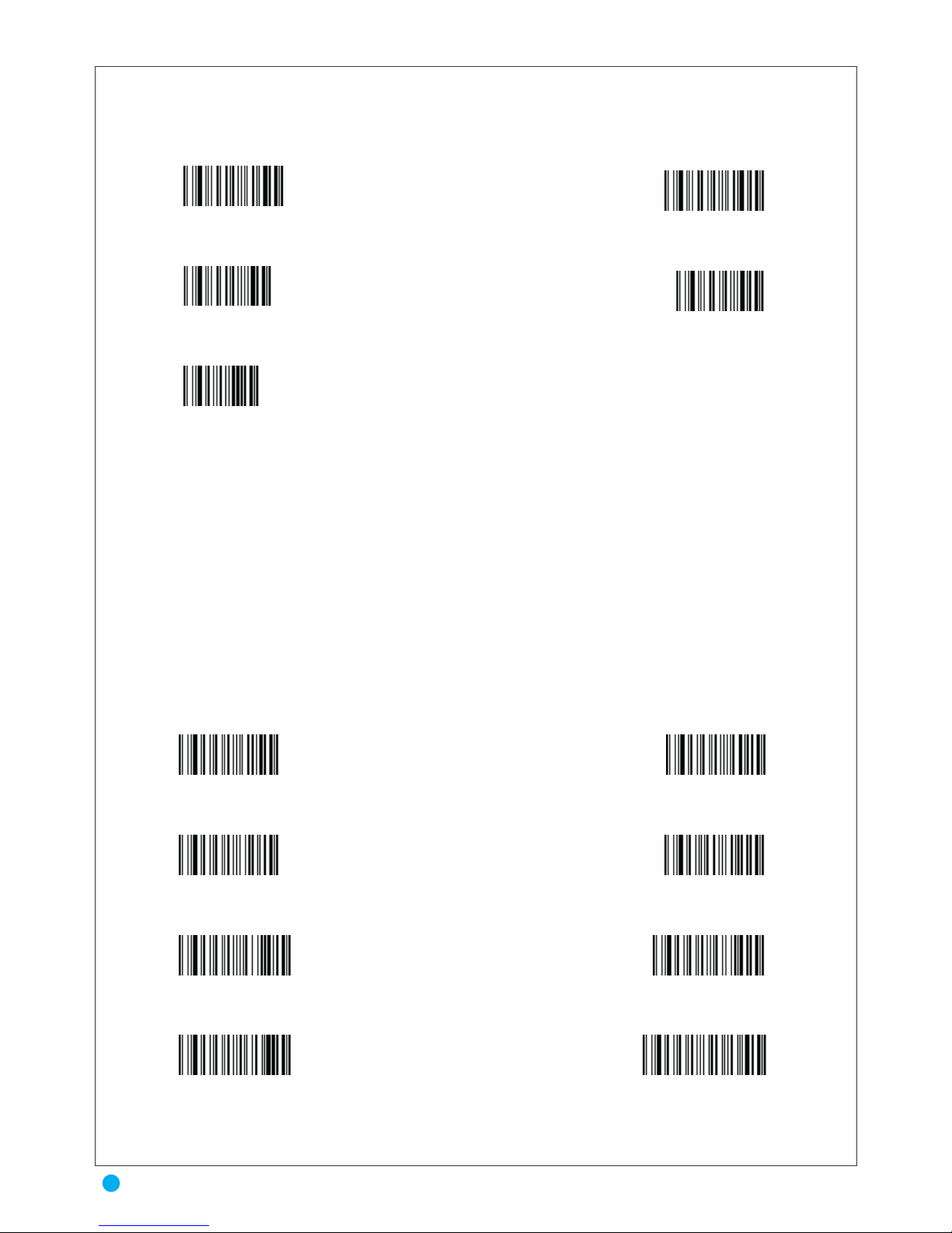
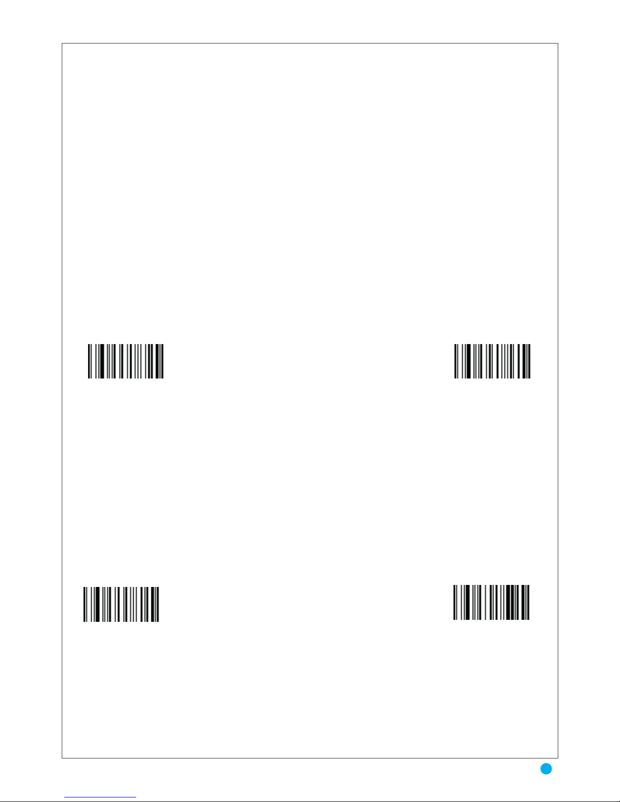
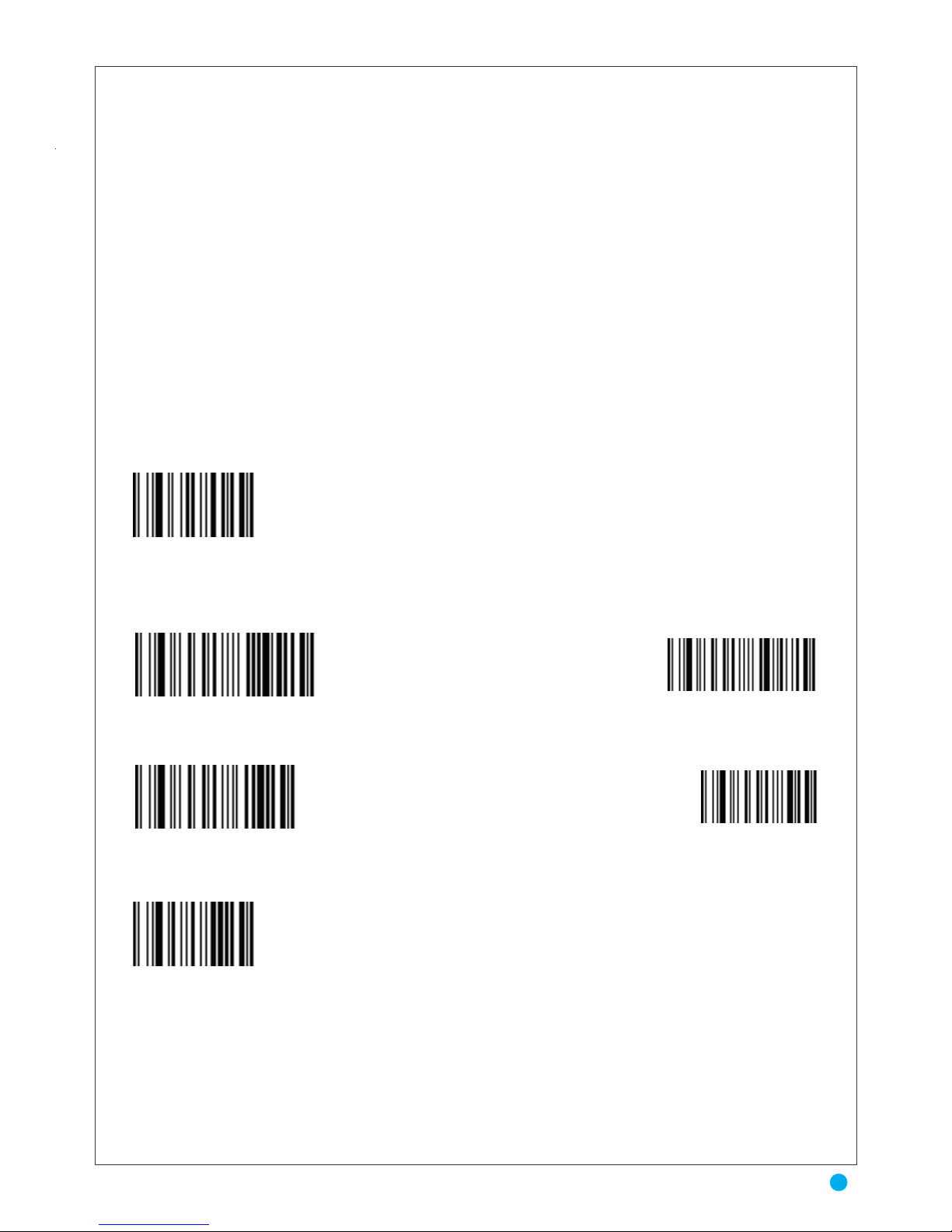
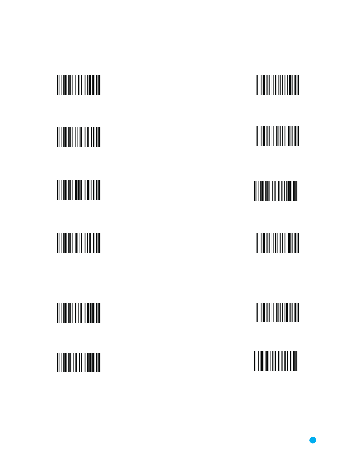
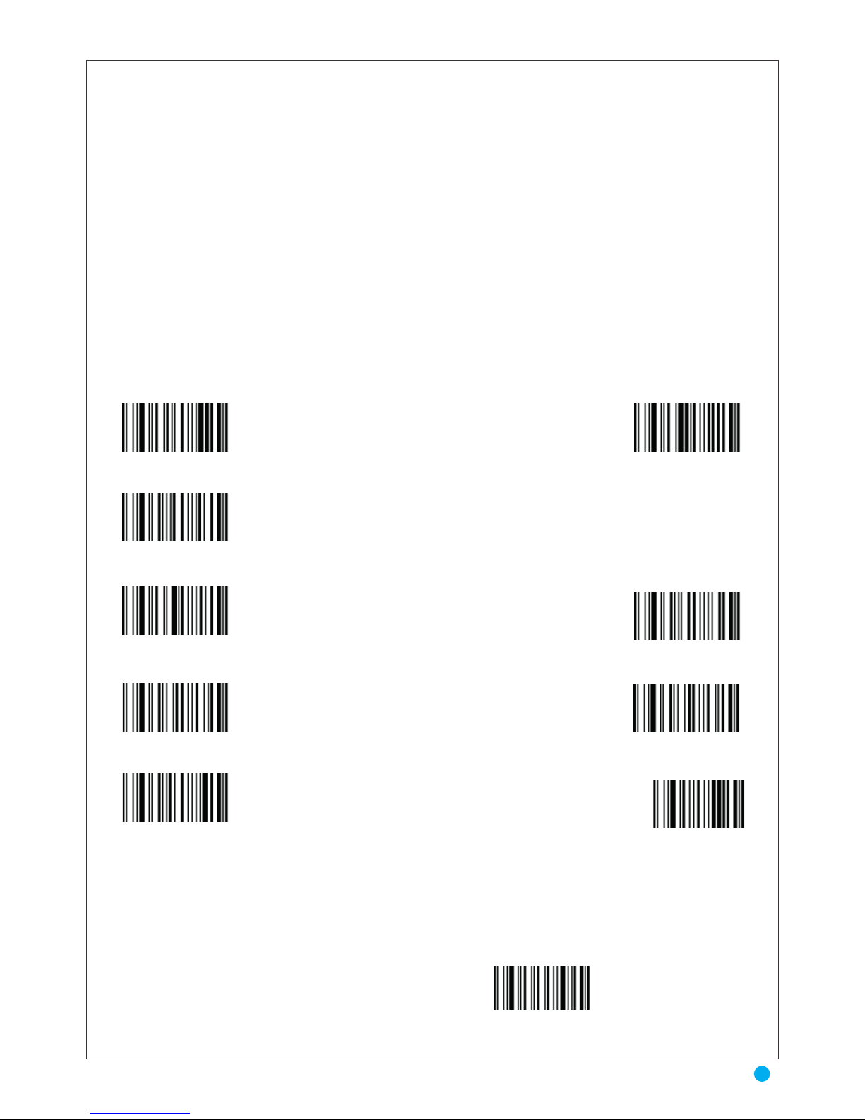
* No Prefix
* No InterChar Delay
20 MilliSec InterChar Delay
100 MilliSec InterChar Delay
1 Sec InterChar Delay
5 MilliSec InterChar Delay
50 MilliSec InterChar Delay
500 MilliSec InterChar Delay
5 Sec InterChar Delay
Setting Prefix
End of Setting
Setting Suffix
* No Suffix
To set Prex with the 3 characters string <HT> <A> <o>
-1 Use the ASCII TABLE to know the hexadecimal value of each character ( HT= 09, 1 = 31, o = 6F)
-2 Scan "Setting Prefix"
-3 Scan "0 and "9" in appendix A for character HT
-4 Scan "3 and "1" in appendix A for character 1
-5 Scan "6 and "F" in appendix A for character o
-6 Scan "End of Setting"
INTER-CHARACTERTER DELAY
This parameter specifies the inter character delay inserted between character transmissions
Auro 2908
6
INTER-CHARACTERTER DELAY
Page 8
Beeper Tone
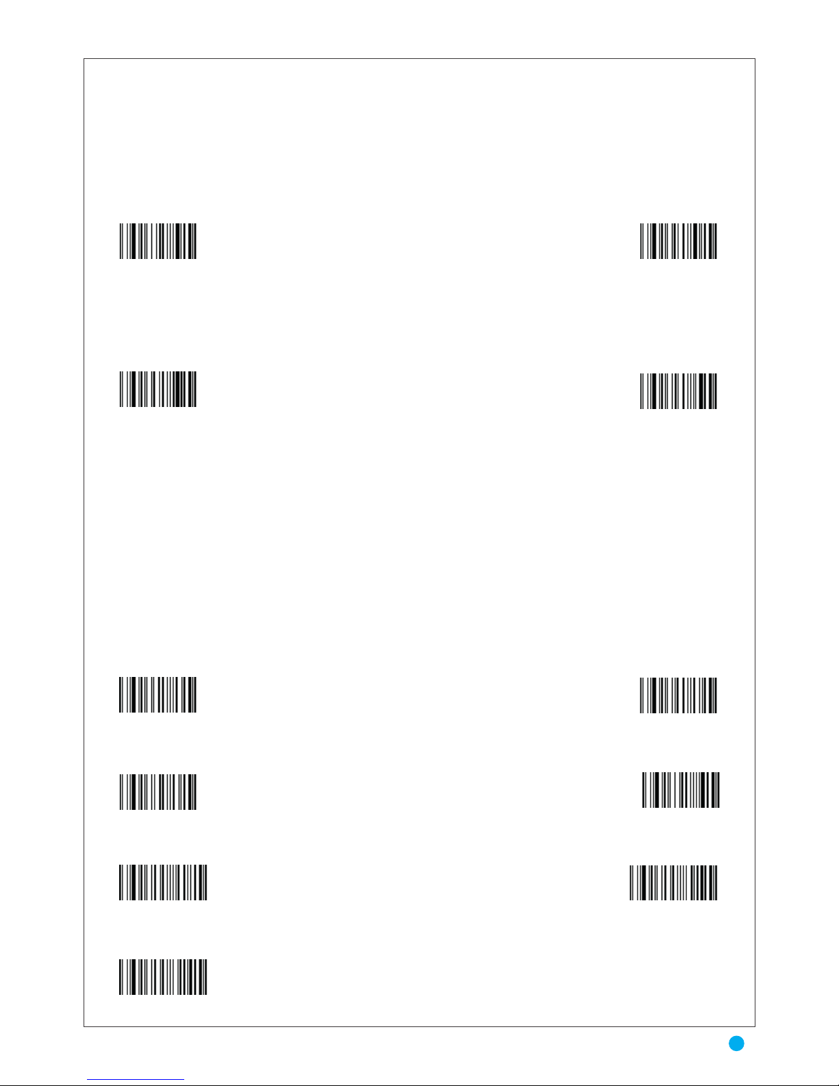
The scanner communicates with the user by emitting different beeper sequences .To select a
decode beep frequency (tone), scan the Beep Decode Activated or Beep Decode Not Activated.
SCANNER MANAGMENT
To select a SCANNER MANAGMENT , scan the TRIGGER MODE for normal scanning
or CCD scanner Flashing mode. For customer Reability , The following will provide the Scanning
variation Scan the code for continuous Read not activated or Continuous Read activated , in case We
flexible to provide One read before Transmission or for reliable Two reads before transmission or
Three Reads before transmission is preferable.
The Decoding Timeout in Trigger Mode can be varied on spécifications of customer, We
provide 3 sec, 6sec and 12sec Decoding timeout in trigger mode.
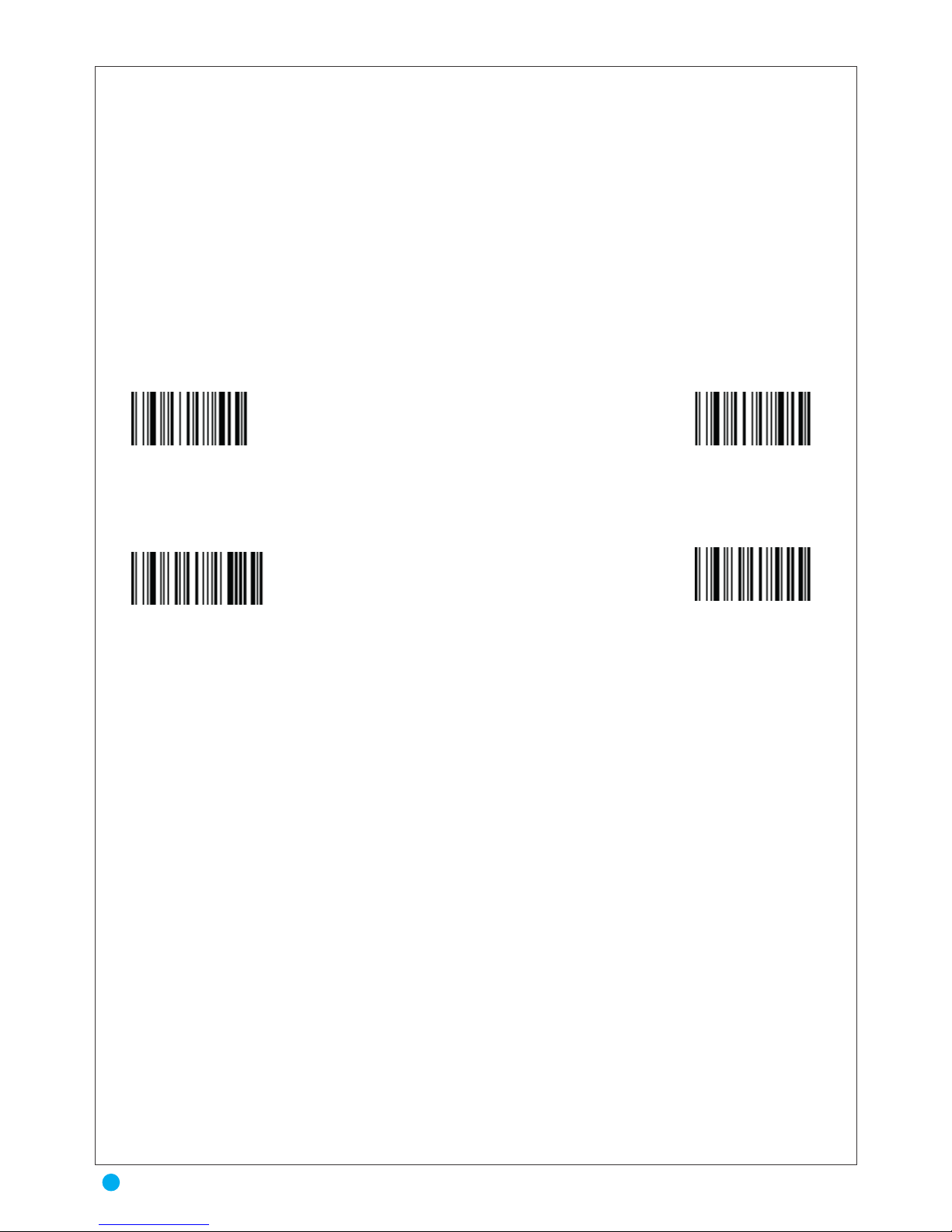
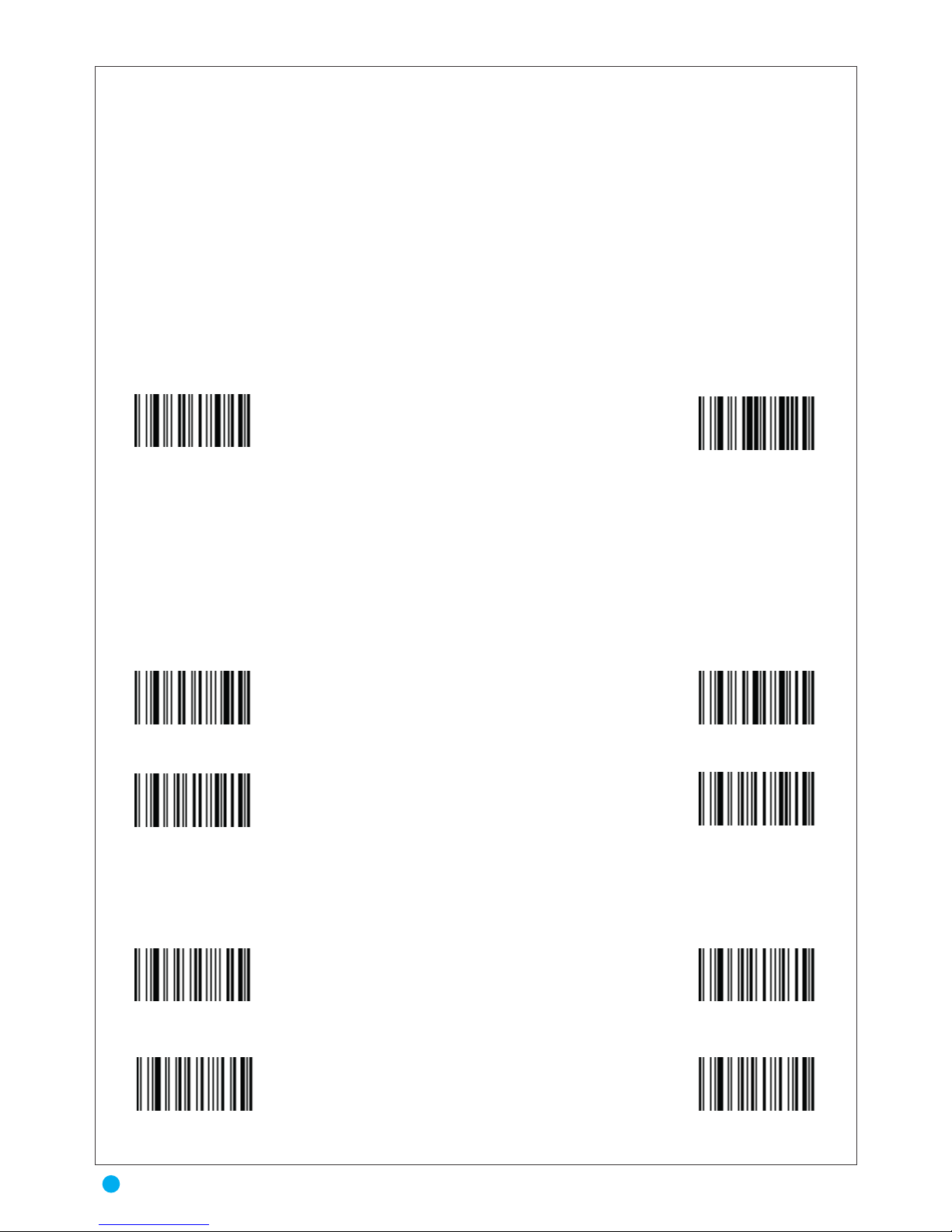
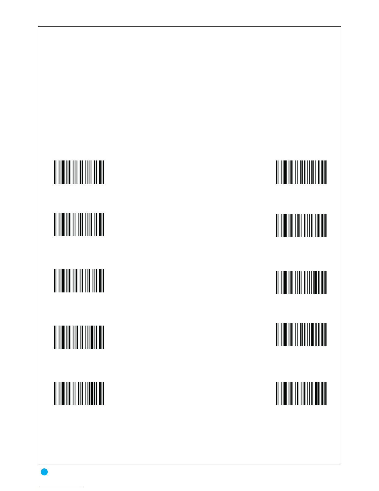
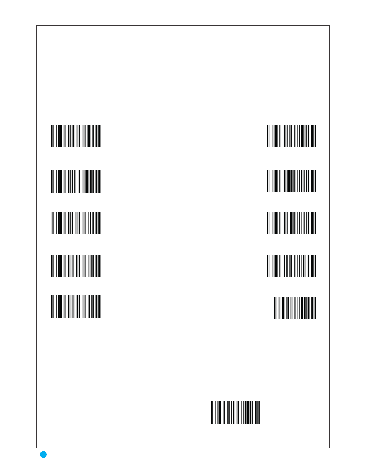
* Beep decode activated
* Identifier not transmitted
Identifier transmitted
Beep decode not activated
* Trigger Mode
* Continuous Read not actived
* One Read before transmission
CCD scanner Flashing mode
Continuous Read actived
Two Reads before transmission
Three Reads before transmission
AIM IDENTIFIER
To select a AIM IDENTIFIER , scan the Identifier not transmitted or Identifier transmitted
7
Beeper Tone & AIM IDENTIFIER & SCANNER MANAGMENT
Page 9
Decode Timeout
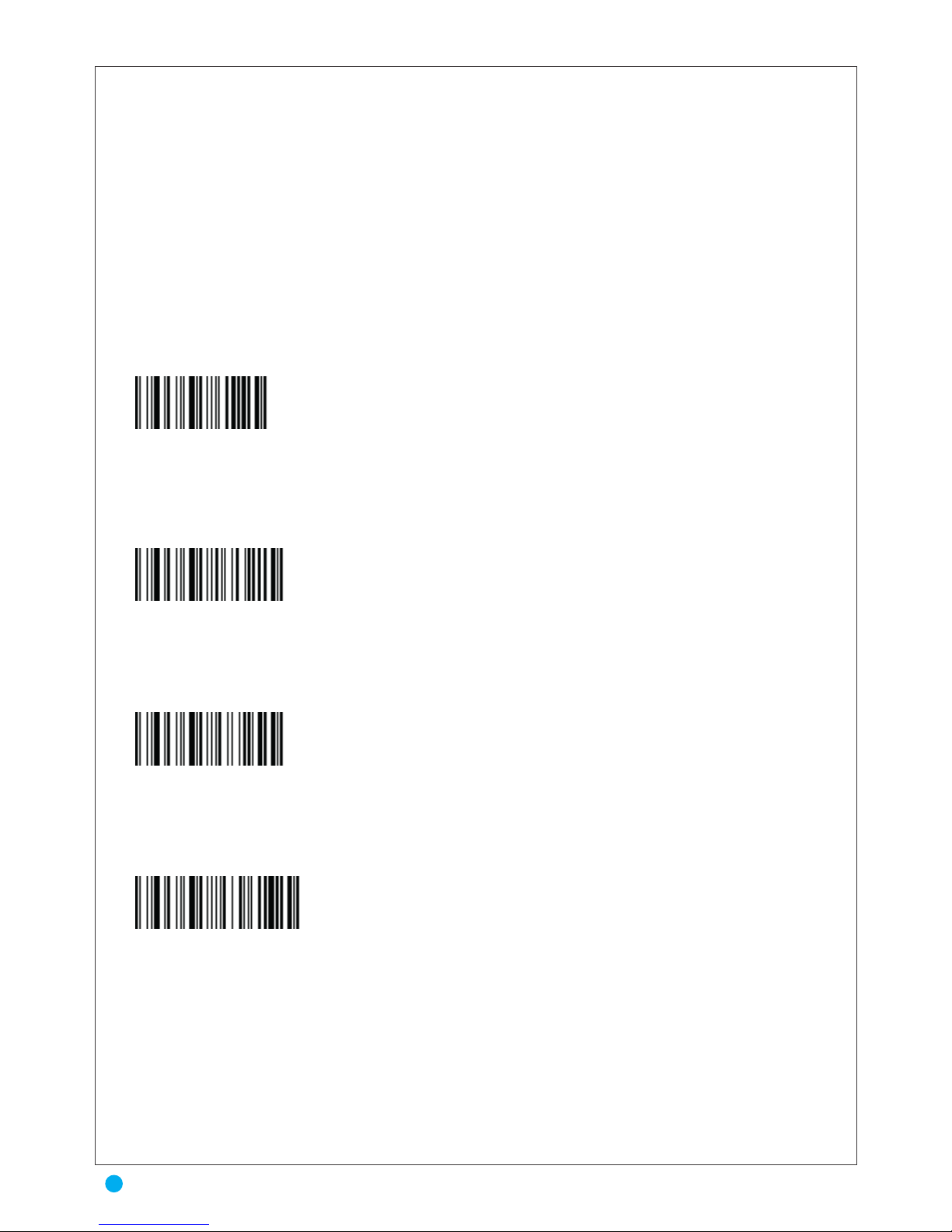
The Undecoded Scanner Emulation Host transmits barcode data to the attached decoder
and waits for the attached decoder to assert the Decode signal, indicating successful transmission. If,
after a specified amount of time, the Decode signal has not been asserted (indicating that the
attached decoder has not successfully received the barcode data), the scanner issues Transmit Error
beeps.
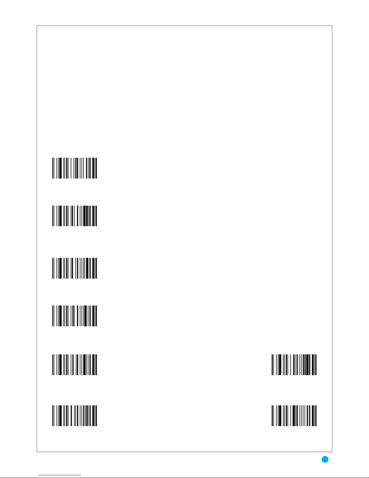
* Decoding Timeout in Trigger Mode not actived
3 Sec Decoding Timeout in Trigger Mode
6 Sec Decoding Timeout in Trigger Mode
12 Sec Decoding Timeout in Trigger Mode
Auro 2908
8
Decode Timeout
Page 10
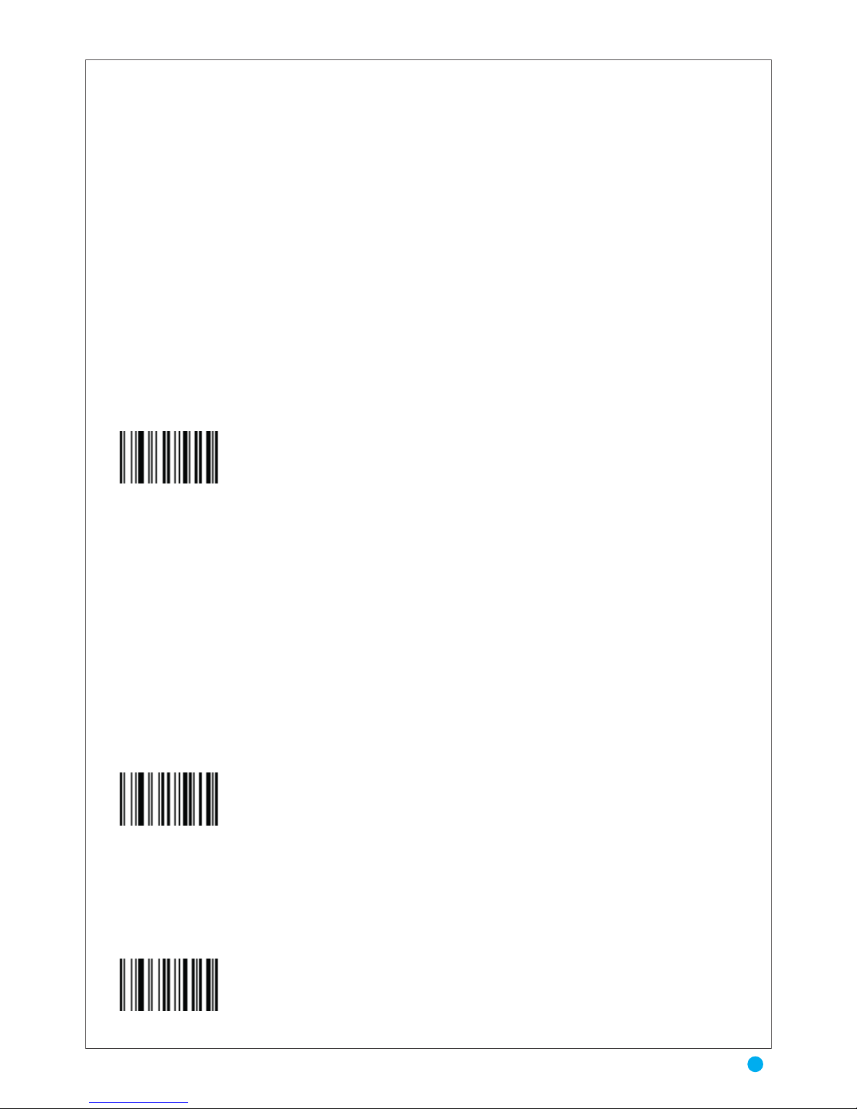
RS232 TRANSMISSION
This chapter covers RS-232 host information for setting up your scanner. The RS-232
interface is used to attach the scanner to point-of-sale devices, host computers, or other
devices with an available RS-232 port (e.g., comport).
You need to set the communication parameters to match your host device. To set communi
cation parameters for hosts not listed, refer to the documentation for the host device
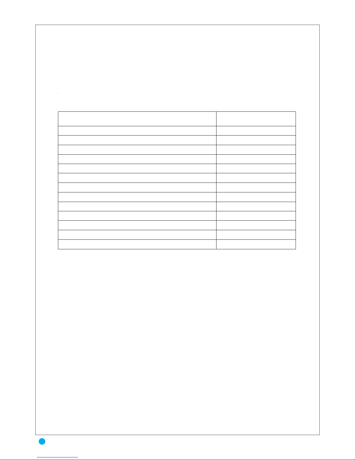
Table 6-1 lists the defaults for RS-232 host parameters. If you wish to change any option, scan the
appropriate bar code(s) provided in the Parameter Descriptions section beginning on page 6-5..
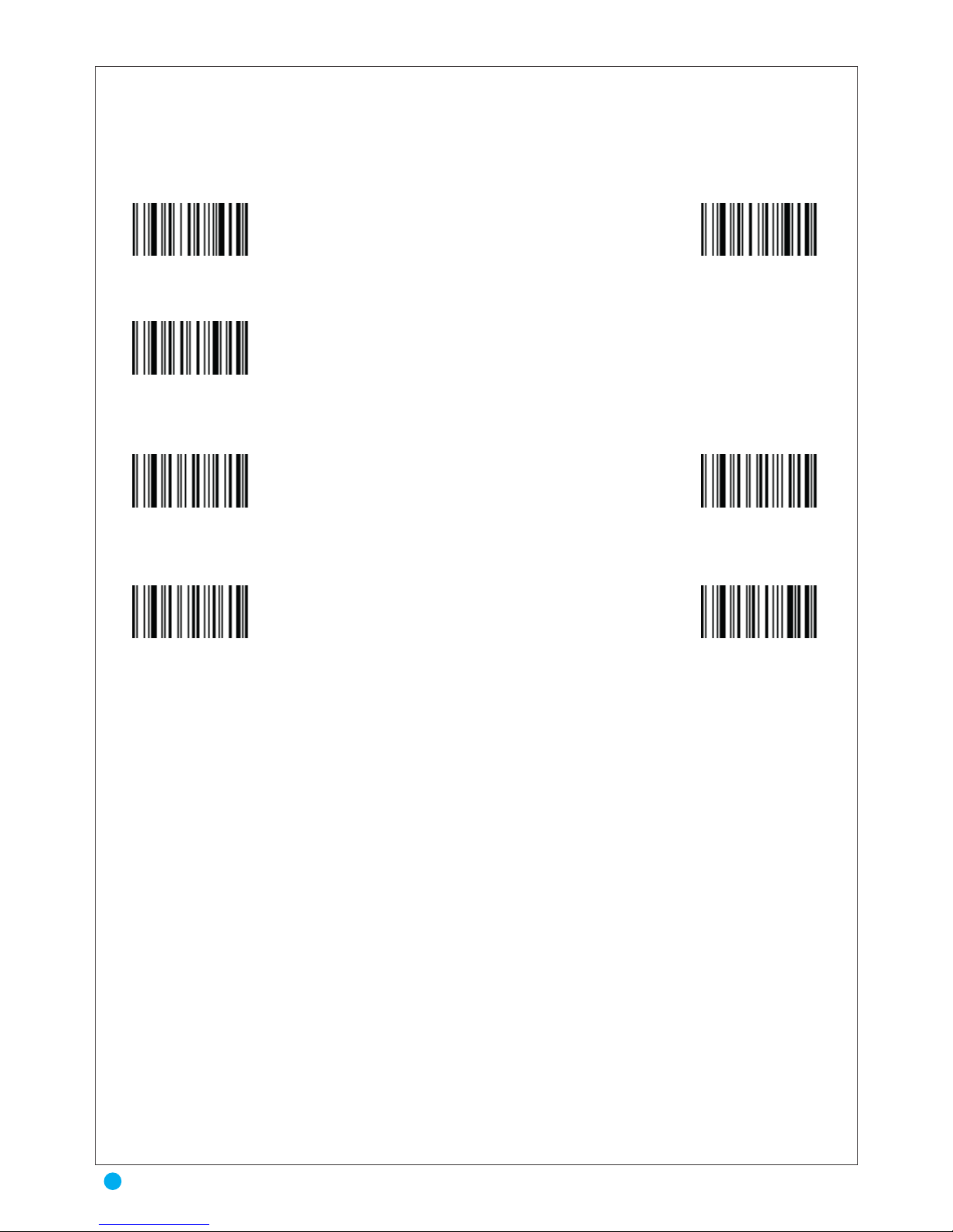
Transmission in RS232 active
USB CDC
USB CDC can be used for industrial equipment such as CNC machinery to allow upgrading
from older RS-232 serial controllers and robotics, since they can keep software compatibility.
The device attaches to an RS-232 communications line and the operating system on the USB
side makes the USB device appear as a traditional RS-232 port. Chip manufacturers such as
Prolific Technology, FTDI, Microchip, and Atmel provide facilities for easily developing
USB RS-232 devices.
The data interfaces are generally used to perform bulk data transfer.
USB CDC
USB HID
The scanner attaches directly to a USB host, or a powered USB hub. No additional power supply in
required
* USB HID
TRANSMISSION
9
TRANSMISSION & RS232 TRANSMISSION
Page 11
Note: See Appendix, Standard Default Parameters for all user preferences, hosts, symbologies, and
miscellaneous default parameters.
Table . RS-232 Host Default Table
RS-232 Host Types
Standard1
Baud Rate
9600
Parity Type
None
Stop Bit Select
1 Stop Bit
Data Bits
8-Bit
Check Receive Errors
Enable
Hardware Handshaking
None
Software Handshaking
None
Host Serial Response Time-out
2 Sec
RTS Line State
Low RTS
Beep on <BEL>
Disable
Intercharacter Delay
0 msec
Nixdorf Beep/LED Options
Normal Operation
Auro 2908
10
TRANSMISSION & RS232 TRANSMISSION
Page 12
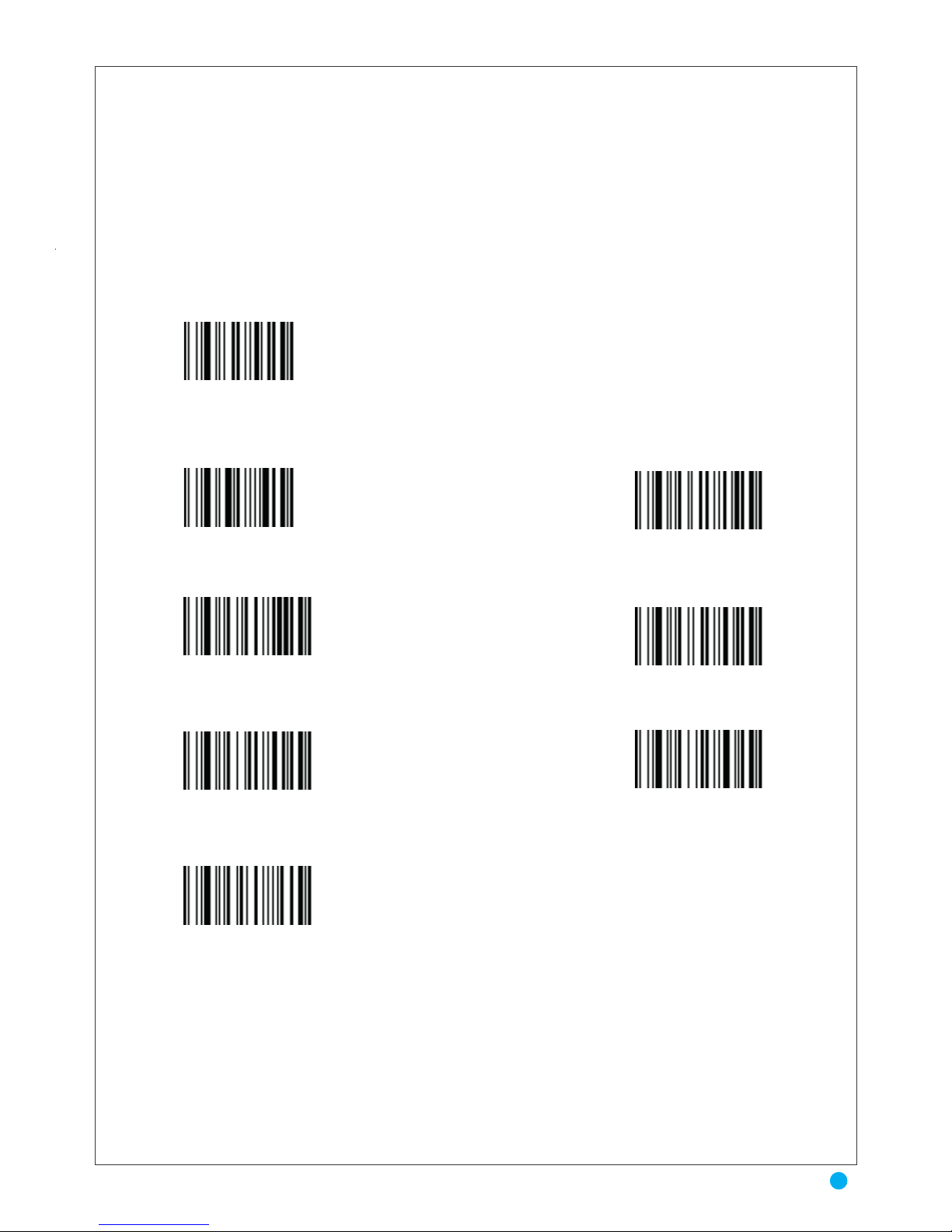
Baud Rate
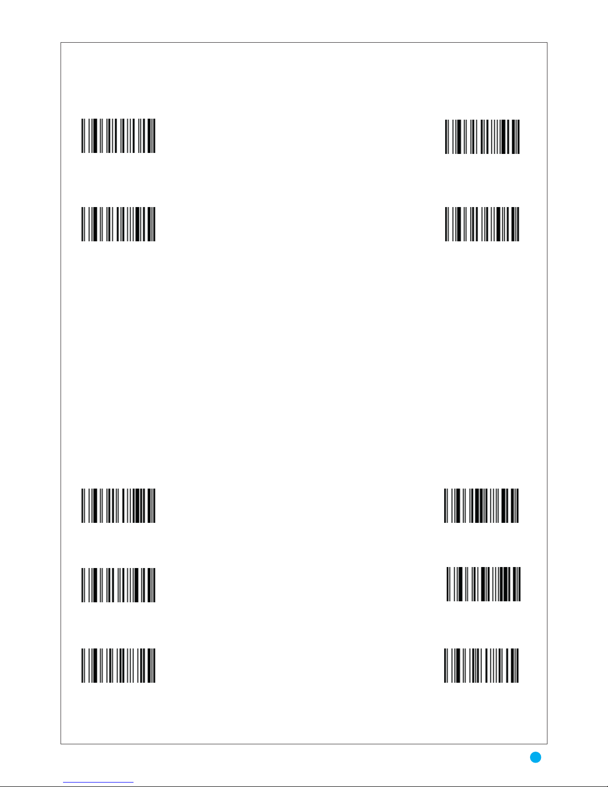
Baud rate is the number of bits of data transmitted per second. The scanner's baud rate
setting should match the baud rate setting of the host device. If not, data may not reach the
host device or may reach it in distorted form.
Transmission in RS232 activated – Cable RS232
300 Bauds
1200 Bauds
4800 Bauds
19200 Bauds
2400 Bauds
* 9600 Bauds
38400 Bauds
11
Baud Rate
Page 13
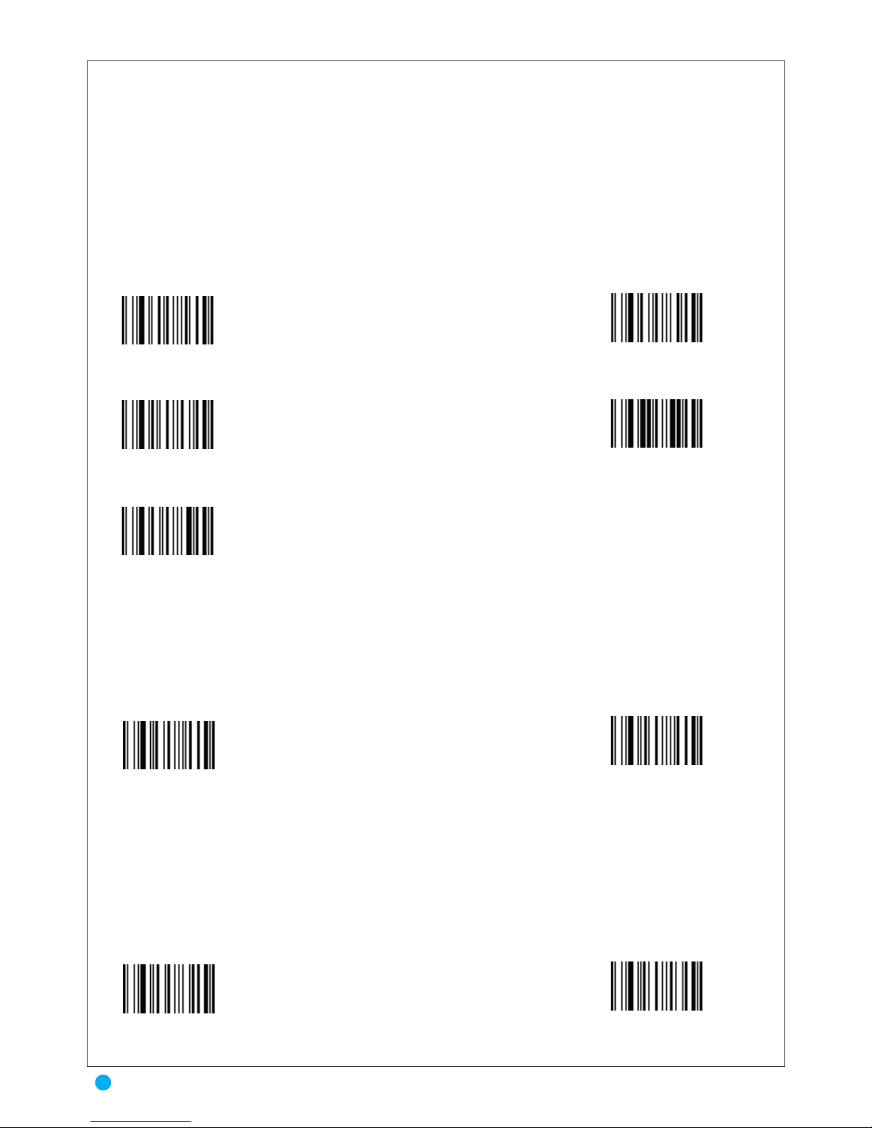
Parity
A parity check bit is the most significant bit of each ASCII coded character. Select the parity
type according to host device requirements.
Select Odd parity and the parity bit value is set to 0 or 1, based on data, to ensure that an
odd number of 1 bits are contained in the coded character.
Data Bits
This parameter allows the scanner to interface with devices requiring a 7-bit or 8-bit ASCII
protocol.
Stop Bit Select
The stop bit(s) at the end of each transmitted character marks the end of transmission of one
character and prepares the receiving device for the next character in the serial data stream. The
number of stop bits selected (one or two) depends on the number the receiving terminal is
programmed to accommodate. Set the number of stop bits to match host device requirements
No Parity
* 7 Data Bits
* 1 Stop Bit
2 Stop Bits
No Parity
Parity Odd
* Parity Even
Parity Mark
Parity Space
Auro 2908
12
Parity & Data Bits & Stop Bit Select
Page 14
XON/XOFF
An XOFF character turns the scanner transmission off until the scanner receives an XON
character.
There are two situations for XON/XOFF:
• XOFF is received before the scanner has data to send. When the scanner has data to
send, it waits up to Host Serial Response Time-out for an XON character before transmis
sion. If the XON is not received within this time, the scanner issues an error indication and
discards the data.
• XOFF is received during a transmission. Data transmission then stops after sending
the current byte. When the scanner receives an XON character, it sends the rest of the data
message. The scanner waits up to 30 seconds for the XON.
Standard RTS\CTS
If the scanner wants to send the barcode data to host computer, it will issue the RTS signal
first, wait for the CTS signal from the host computer, and then perform the normal data
communication. If there is no replied CTS signal from the host computer after the timeout
(Response Delay) duration, the scanner halts transmission until it detects another active CTS
signal.
Scan the bar code below to select Standard RTS\CTS Hardware Handshaking.
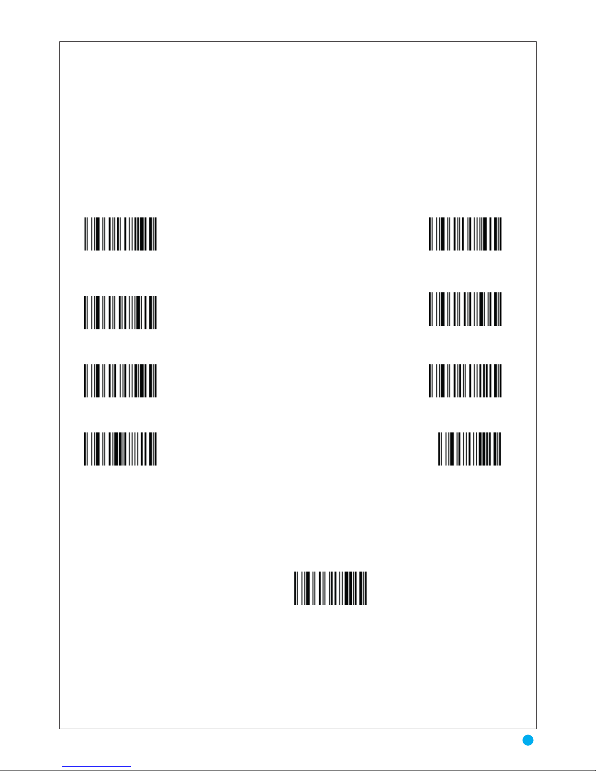
* Xon/Xoff protocol not actived Xon/Xoff protocol actived
* Cts/Rts protocol not actived Cts/Rts protocol actived
13
XON/XOFF & Standard RTS\CTS
Page 15
ENQ
When this option is selected, the scanner waits for an ENQ character from the host before
transmitting data. If an ENQ is not received within the Host Serial Response Time-out, the
scanner issues an error indication and discards the data. The host must transmit an ENQ
character at least every Host Serial Response Time-out to prevent transmission errors.
* Enquiry character from Host not actived Enquiry character from Host actived
* Enquiry character from Host = Enq ( 05 ) Setting Enquiry character from Host
Auro 2908
14
ENQ
Page 16
ACK/NAK
When this option is selected, after transmitting data, the scanner expects either an ACK or
NAK response from the host. When a NAK is received, the scanner transmits the same data again
and waits for either an ACK or NAK. After three unsuccessful attempts to send data when NAKs
are received, the scanner issues an error indication and discards the data.
The scanner waits up to the programmable Host Serial Response Time-out to receive an
ACK or NAK. If the scanner does not get a response in this time, it issues an error indication and
discards the data. There are no retries when a time-out occurs.
When the ACK/NAK protocol is used, the scanner waits for an ACK (acknowledge) or (not
acknowledge) from the host computer after data transmission, and will resend in response to a
NAK.
*Ack/Nak protocol not actived
* Character Ack from
Ack/Nak protocol = Ack ( 06)
* Character Nak from
Ack/Nak protocol = Nak (15 Hex)
Ack/Nak protocol actived
Setting character Ack from
Ack/Nak protocol
Setting character Nak from
Ack/Nak protocol
End of Setting
* Terminator = CR LF (0D, 0A Hex) No Terminator
Setting TerminatorTerminator = CR (0D Hex)
End of Setting
15
ACK/NAK
Page 17
RS232 TIMEOUT
RTS/CTS-If the scanner wants to send the barcode data to host computer, it will issue the
RTS signal first, wait for the CTS signal from the host computer, and then perform the
normal data communication. If there is no replied CTS signal from the host computer after
the timeout (Response Delay) duration, the scanner halts transmission until it detects another
active CTS signal.
In case of RTS/CTS, Enquiry and Ack/Nak protocol, the scanner is waiting for an answer
of the Host.
A actived timeout allows the scanner to abort the transmission.
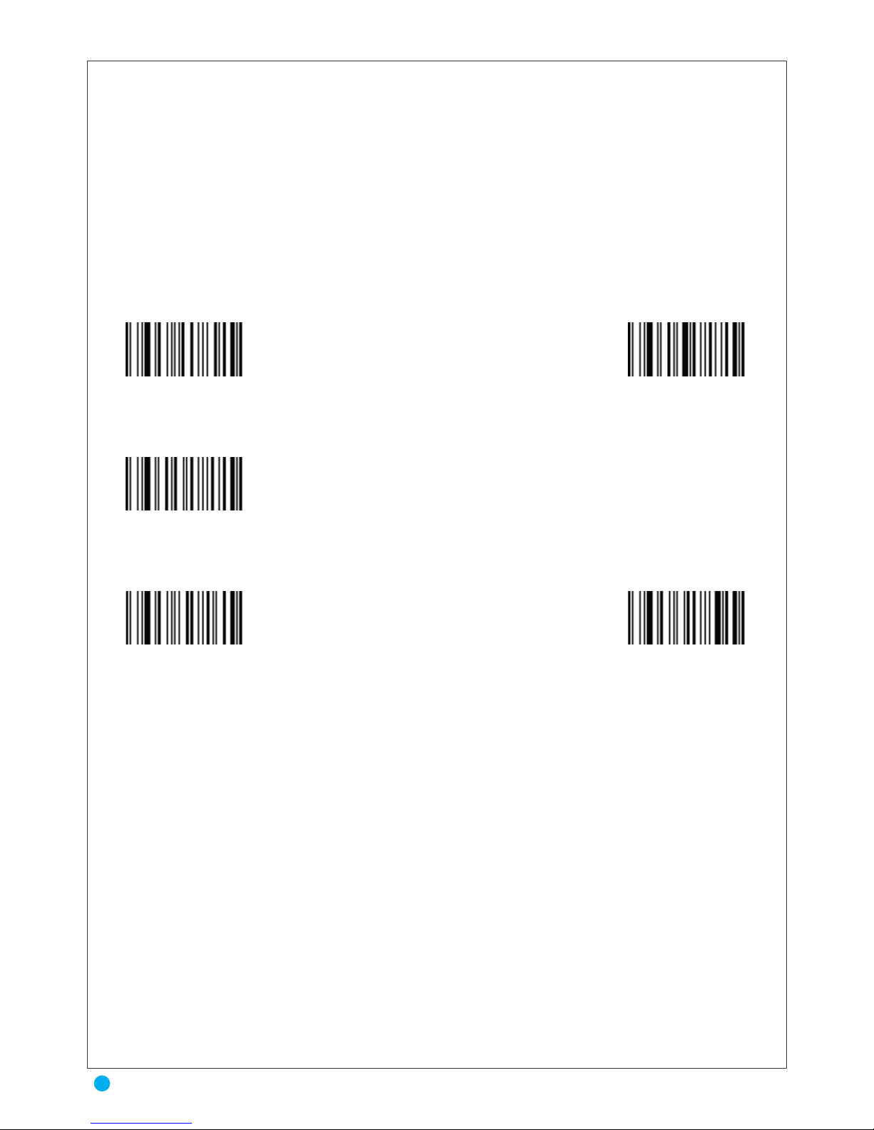
* Timeout not actived
3 Sec Timeout
1 Sec Timeout
5 Sec Timeout
10 Sec Timeout
Auro 2908
16
RS232 TIMEOUT
Page 18
WEDGE TRANSMISSION
This chapter covers Keyboard Wedge interface information for setting up your scanner. This
interface type is used to attach the scanner between the keyboard and host computer.
The scanner translates the bar code data into keystrokes. The host computer accepts the key
strokes as if they originate from the keyboard This mode of operation allows adding bar code
reading functionality to a system designed for manual keyboard input. In this mode the keyboard
keys trokes are simply passed
through.
Throughout the programming bar code menus, default values are indicated with asterisks
* USB HID
No Terminator
* Terminator = Enter Keyboard
Setting Terminator
Terminator = Enter Keypad
End of Setting
17
WEDGE TRANSMISSION
Page 19
SYMBOLOGY
Many bar code symbologies have been developed to suit many data capture applications in
different domains (retail, industry, medical, transport,…) requiring simple or complete sets of
characters (numeric , alpha-numeric, full ASCII set….) with various density performances. Each
symbology has options which must be carefully checked and adjusted by the user. Some examples
are printed inside the last cover of this manual.
Enable/Disable UPC-A/ UPC-E
To enable or disable UPC-A or UPC-E, scan the appropriate bar code below.
Enable/Disable Code 39
To enable or disable Code 39, scan the appropriate bar code below.
Trioptic Code 39 is a variant of Code 39 used in the marking of computer tape cartridges.
Trioptic Code39 symbols always contain six characters. To enable or disable Trioptic Code
39, scan the appropriate bar code below.
Enable/Disable Codabar
To enable or disable Codabar, scan the appropriate bar code below.
UPC / EAN Not actived * UPC / EAN Actived
CODE 39 Not actived * CODE 39 Actived
CODE 128 Not actived * CODE 128 Actived
* CODABAR Not actived CODABAR Actived
* INTERLEAVED 2/5 Not actived
INTERLEAVED 2/5 Actived
Auro 2908
18
SYMBOLOGY & Enable/Disable UPC-A/ UPC-E
Page 20
MSI Check Character
Different types of check characters are used with MSI barcodes. You can program the
scanner to read MSI barcodes with Type 10 check characters.
When Check Character is set to Validate and Transmit, the scanner will only read MSI
barcodes printed with the specified type check character, and will transmit this character at the end
of the scanned data. When Check Character is set to Validate, but Don’t Transmit, the unit will only
read MSI barcodes printed with the specified type check character, but will not transmit the check
character with the scanned data.
Enable/Disable MSI
To enable or disable MSI, scan the appropriate bar code below.
* STANDARD 2/5 Not actived
* MATRIX 2/5 Not actived
* MSI Not actived
* PLESSEY Not actived
* CODE 93 Not actived
MSI Actived
PLESSEY Actived
CODE 93 Actived
STANDARD 2/5 Actived
MATRIX 2/5 Actived
19
MSI Check Character & En Enable/Disable MSI
Page 21
UPC/EAN
This symbology is mainly used for retail applications. It has fixed lengths (8 or 12 char. For
UPC, 8 or 13.char. for EAN) and uses a check digit as the last character and is only numeric. Two or
five supplemental digits are called ADD-ON can be added to the right hand side of the codes.
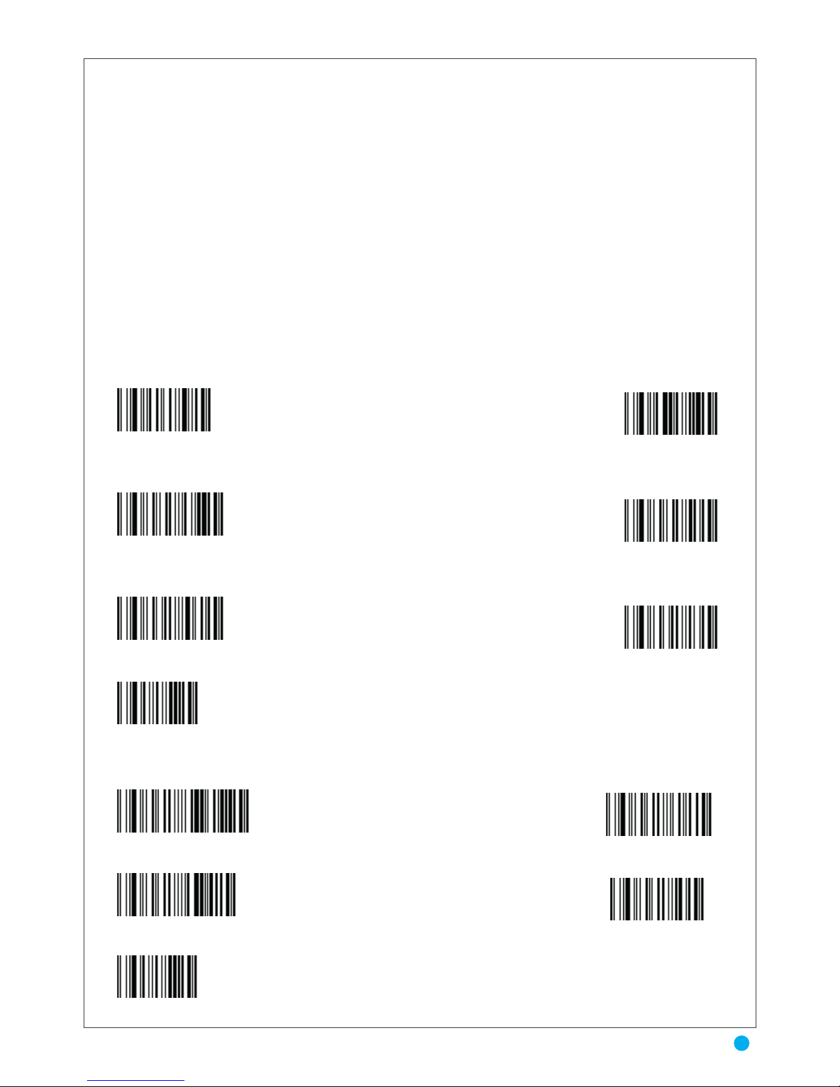
* Addon 5 Not actived
* Addon 2 Not actived
* Read Single UPC/EAN and
UPC/EAN with Addon
* Leading digit UPCA
transmitted
* Check digit UPCA
transmitted
UPCA transmitted as EAN13
(13 characters)
* Leading digit UPCE
transmitted
Addon 5 Actived
Addon 2 Actived
Read Only UPC/EAN
with Addon
Leading digit UPCA not
transmitted
Check digit UPCA
not transmitted
* UPCA transmitted as
UPCA (12 chars)
Leading digit UPCE not
transmitted
Auro 2908
20
UPC/EAN
Page 22
* Check digit UPCE transmitted
UPCE transmitted as UPCA
* Check EAN8 transmitted
EAN8 transmitted as EAN13
* Check digit EAN13 transmitted
ISBN EAN13 actived
Check digit UPCE not transmitted
UPCE transmitted as UPCA
Check digit EAN8 not transmitted
* EAN8 transmitted as EAN8
Check EAN13 non transmis
* ISBN EAN13 not actived
21
UPC/EAN
Page 23
CODE 39
Code pages define the mapping of character codes to characters. If the data received does
not display with the proper characters, it may be because the barcode being scanned was created
using one the host program is expecting. If this is the case, scan the barcode below, select the code
page with which the barcodes were created and scan the value and the Save barcode. The data
characters should then appear properly.
This is the most popular alpha-numeric bar code symbology. It has a set of 43 characters
(alphanumeric and few symbols) and can be used with or without a check digit.
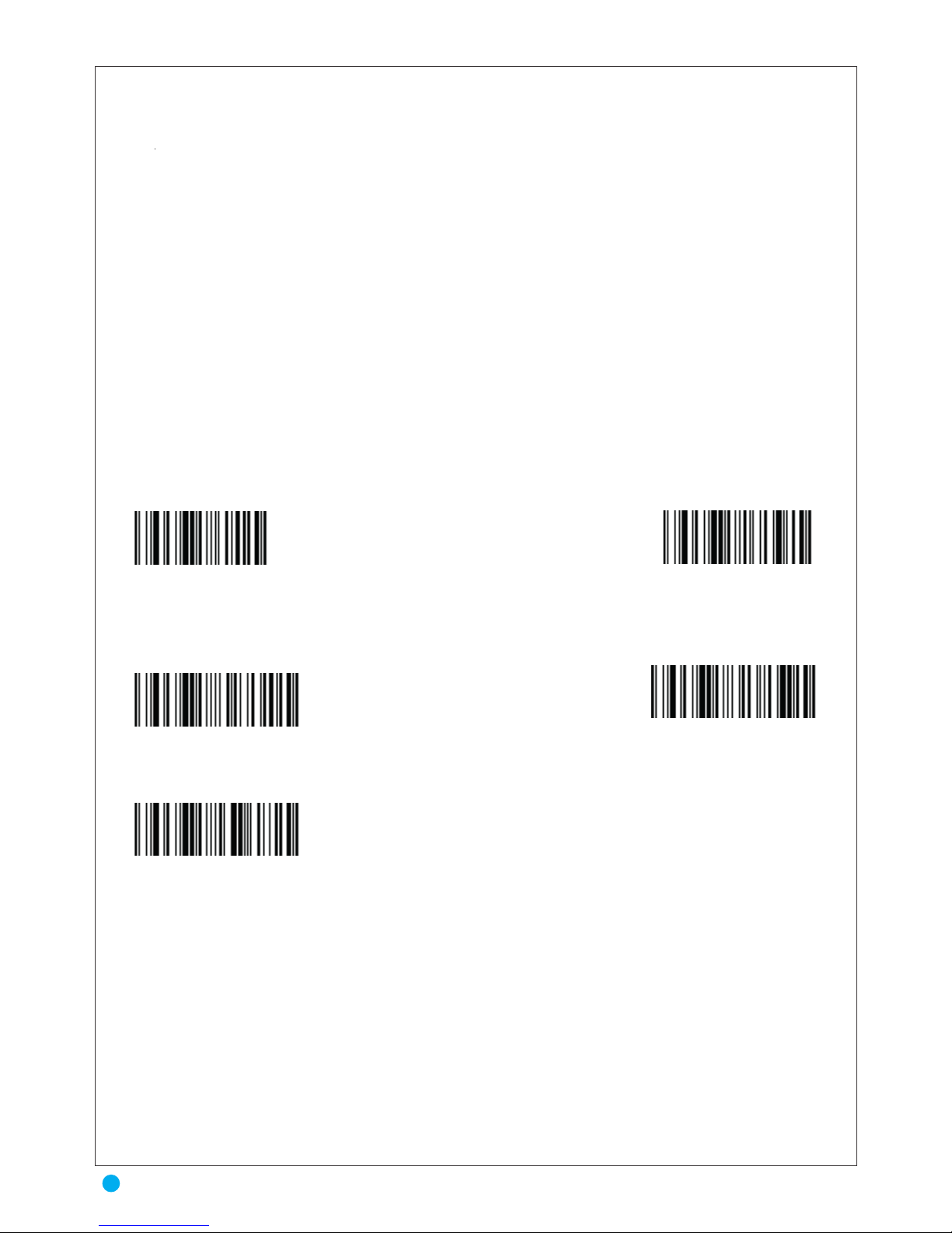
Standard
* Start/Stop not transmitted
* Check Digit not verified
Check Digit Cip verified
* Check Digit not transmitted
* Full Ascii
Start/Stop transmitted
Check Digit Modulo 43 verified
Check Digit I Cip verified
Check Digit transmitted
Auro 2908
22
CODE 39
Page 24
CODABAR
The Coda bar (or Monarch) is a very high reliable bar code which has been designed especially for medical applications such as blood bag identification. Its character set contains numerics
and four symbols. This function permits the capture of two codes with only one scan. Codes must
be close to one another and on the same “line”.
Note: to operate this function correctly, the first code must end with the “d” stop character and the
second code must start with the “d” start character. These two start/stop characters are cleared
before transmission
* Single Code
Two adjacent codes ABC (Stop character of first barcode = Start character of second barcode = D)
Two adjacent code with Stop character of first barcode = Start character of second barcode
All adjacent codes
* Read adjacent codes only
* Start/Stop Not transmitted
* Read adjacent codes only
* Start/Stop Not transmitted
23
CODABAR
Page 25
* Single Code
All adjacent codes
* Read adjacent codes only
* Start/Stop Not transmitted
* Single Code
* Read adjacent codes only
* Start/Stop Not transmitted
Auro 2908
24
CODABAR
Page 26
2/5 ENTRELACE
This symbology encodes a pair of digits in each symbol, the number of digits are always an
even number. Information is carried in the bars and spaces. The start and stop pattern is not unique
inside the code. It is therefore essential to use the fixed length option to prevent partial reads
The bar code 2/5 interleaved is a bidirectional digital barcode. This bar code says "Interleaved 2 of 5" uses the same encoding scheme as the bar code 2/5 (2 of 5) but intertwining characters in pairs. This means that the first character is coded with the bars while the second character
uses the spaces of the same area. Since the bars and spaces codify characters, the bar code 2/5
interleaved performed in all cases, encoding an even number of characters. The odd numbers are
coded with the bars, and the numbers of even rank are coded with spaces. The term 2/5 interleaved
is because we use for each character 5 elements 2 are still large.
To choose 2 lengths 8 and 16 characters
--1 Scan "Setting Length N°1"
-2 Scan decimal value "8" in Appendix A
-3 Scan "End of Setting"
-4 Scan "Setting Length N°2"
-5 Scan decimal values "1" and "6" in Appendix A
-6 Scan "End of Setting"
* Check Digit Modulo not verified
Check Digit CIP HR verified
* Check Digit not transmitted
Setting Length N° 1
Setting Length N° 3
Variable Length (Check Digit Modulo 10 verified)
Check Digit Modulo 10 verified
Check Digit transmitted
Setting Length N° 2
End of Setting
25
2/5 ENTRELACE
Page 27
2/5 STANDARD
The code 39 FULL ASCII option allows the transmission of the 128 ASCII characters.
Each ASCII character is a combination of two code 39 character. It can be very be use full specially
to transmit control characters (STX, ETX, TAB, EOT…..) as PREAMBLES or POSTAMBLES in
a message (see appendix 2). The code 39 FULL ASCII Table is listed in appendix 13.
To choose 2 lengths 10 and 12 characters
-1 Scan "Setting Length N°1"
-2 Scan decimal values "1" and "0" in Appendix A
-3 Scan "End of Setting"
-4 Scan "Setting Length N°2"
-5 Scan decimal values "1" and "2" in Appendix A
-6 Scan "End of Setting"
Variable Length (Check Digit Modulo 10 verified)
* Start/Stop 6 barres
* Check Digit not verified
* Check Digit not transmitted
Setting Length N° 1
Setting Length N° 3
Start/Stop 4 barres
Check Digit Modulo 10 verified
Check Digit transmitted
Setting Length N° 2
End of Setting
Auro 2908
26
2/5 STANDARD
Page 28
2/5 MATRIX
Message Length
Scan the barcodes below to change the message length. Minimum and Maximum lengths =
1-80. Minimum Default = 4, Maximum Default = 80.
This symbology encodes 1 digit in each character, the number of digits can therefore be an
odd or an even number. Information is carried in the bars and spaces.
To choose 1 length 14 characters
-1 Scan "Setting Length N°1"
-2 Scan decimal values "1" and "4" in Appendix A
-3 Scan "End of Setting"
* Check Digit not verified
* Check Digit not transmitted
Setting Length N° 1
Setting Length N° 3
Check Digit verified
Check Digit transmitted
Setting Length N° 2
End of Setting
Variable Length (Check Digit verified)
27
2/5 MATRIX & Message Length
Page 29
MSI
This symbology is mainly used in libraries to trace the loan of books. It is only numeric and
due to its very simple encoding system it can be used only with a fixed length or with variable
lengths when including one or two check digits.
* Check Digit modulo 10 verified
Check Digit not verified
* Check Digit not transmitted
Check Digit double modulo 10
Check Digit transmitted
Auro 2908
28
MSI
Page 30
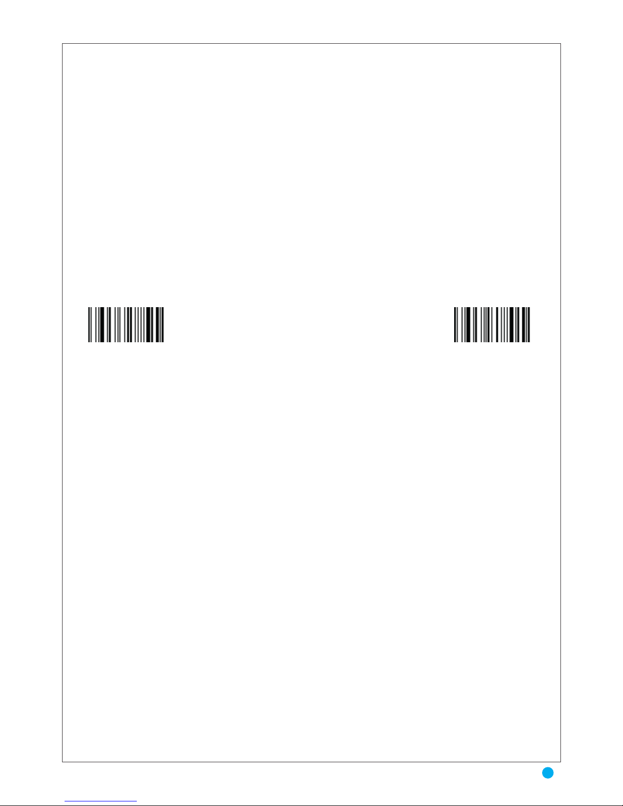
PLESSEY
Message Length
Plessey is a variable length symbology with a mandatory checksum and non printable start/
stop characters. The following characters are supported:
• the digits 0 upto 9
• the characters A upto F
The checksum contains 2 digits and is calculated from the numerical values of all the data digits.
Scan the barcodes below to change the message length. Minimum and Maximum lengths = 4-48.
Minimum Default = 4, Maximum Default = 48.
* Check Digit not transmitted Check Digit transmitted
29
PLESSEY & Message Length
Page 31
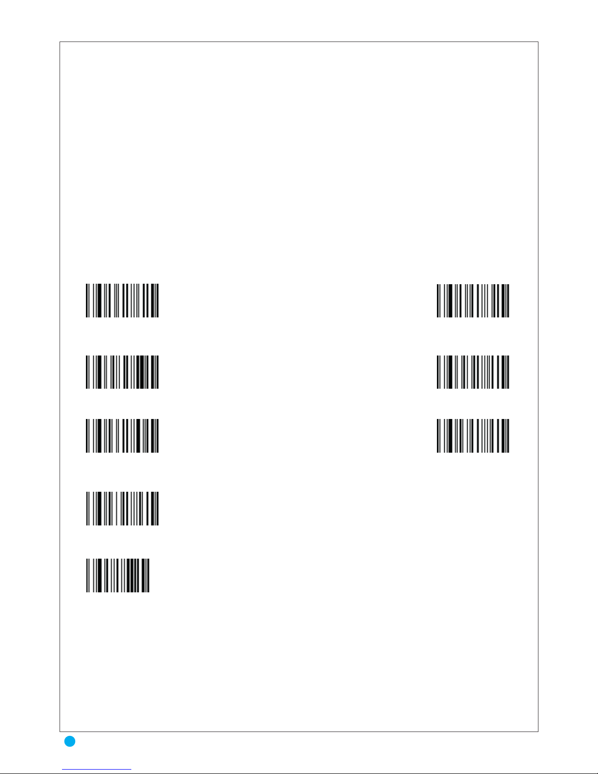
EAN 128
A high density symbology which allows the controller to encode all 128 .ASCII characters
without adding extra symbol elements.
Similar Automatic Identification Manufacturers, Inc. of the United States(AIMUSA) have
standardized the reporting of data sources from barcode reading devices. Sending the AIM symbology prefix identifies the symbology to the host terminal, allowing it to specifically differentiate
between UCC-128(Code128 with Function Character 1 in the first position ) and standard Code128
symbols. When this feature is disabled, the host cannot differentiate between these symbols.
Scan the labels below to enable or disable the sending of an AIM symbology
ID prefix.
To choose Separator EAN 128 = <GS>
-1 Use the ASCII TABLE to know the hexadecimal value of character GS ( GS = 1D)
-2 Scan " Setting separator EAN 128 "
-3 Scan "1" and "D" in appendix A
-4 Scan "End of Setting"
* Check Digit Code 128 Cip not verified
EAN 128 Not actived
EAN 128 Separator = ]C1
Check Digit Code 128 Cip verified
* EAN 128 Actived
* EAN Separator = GS
Setting EAN 128 Separator (* Default = GS
End of Setting
Auro 2908
30
EAN 128
Page 32
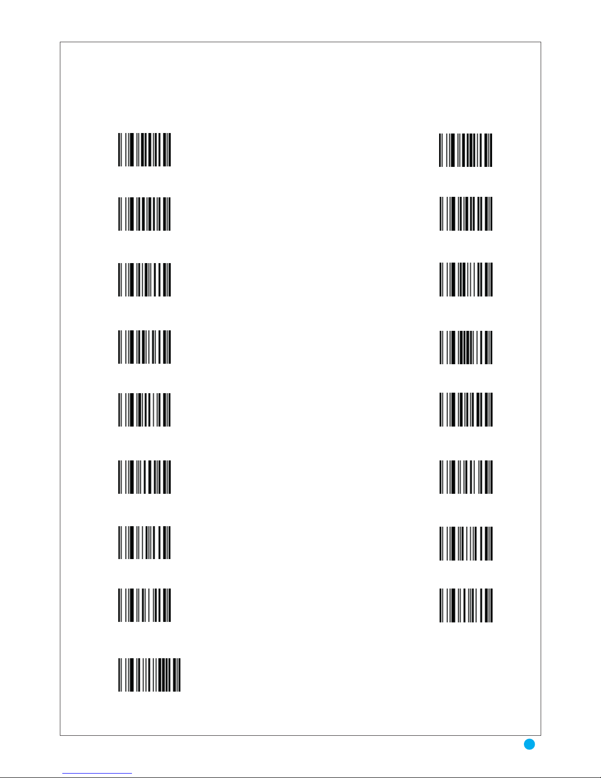
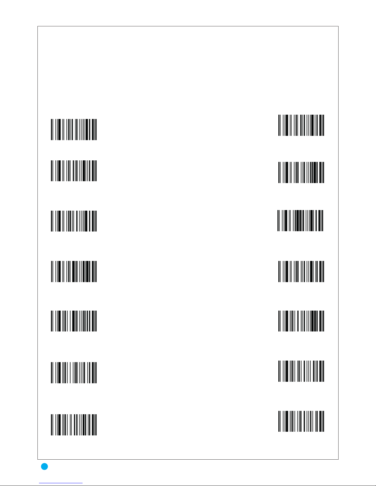
APPENDIX A
0
2
4
6
8
A
C
E
End of Setting
1
3
5
7
9
B
D
F
31
Appendix
Page 33
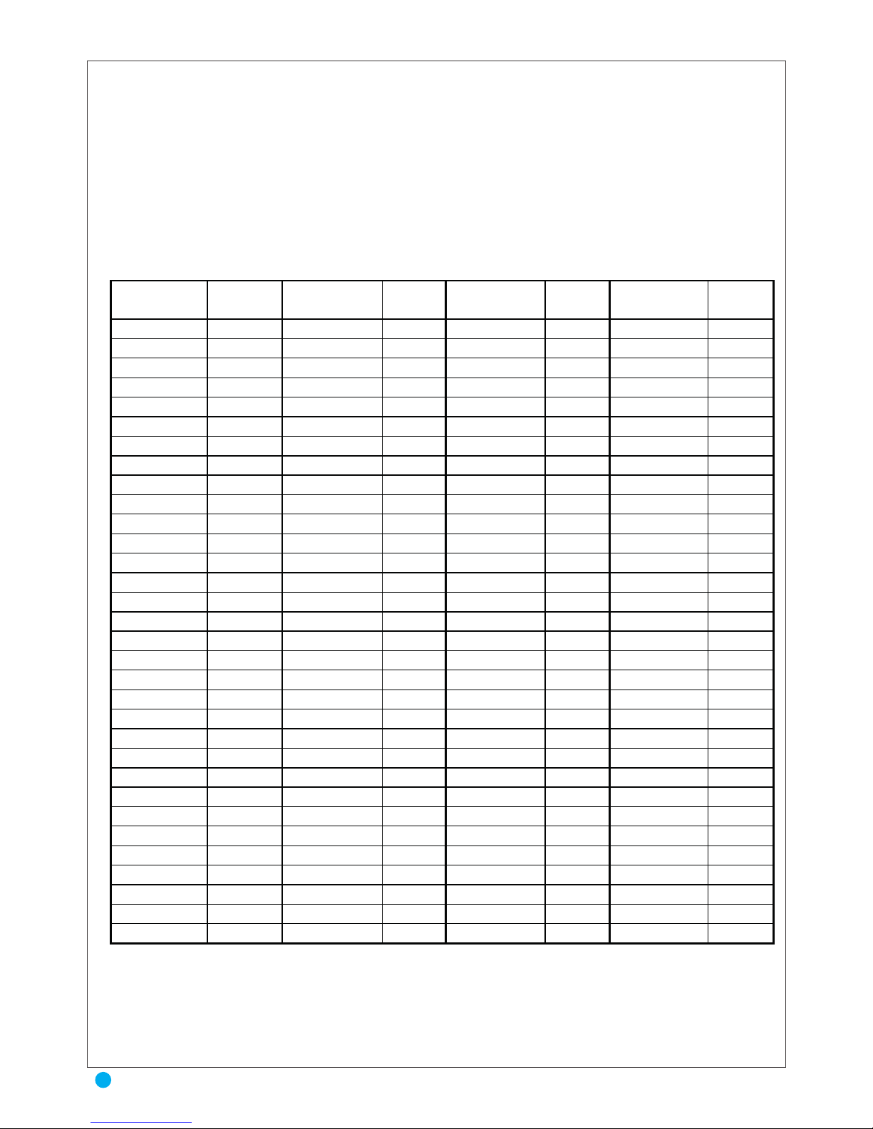
ASCII TABLE
In keyboard-wedge mode, function keys like F1 to F12 , →, HOME, CLEAR…… can be
emulated using this option. The function key to be emulated is represented by two code 39 characters from the CODE 39 FULL ASCII EXTENDED table on, which can be part of the symbol or
separate from it.
Character
Hexa
Val
Character
Hexa
Val
Character
Hexa
Val
Character
Hexa
Val
NULL
00
SP
20 @ 40 ` 60
SOH
01 ! 21 A 41 a 61
STX
02 " 22 B 42 b 62
ETX
03 # 23 C 43 c 63
EOT
04 $ 24 D 44 d 64
ENQ
05 % 25 E 45 e 65
ACK
06 & 26 F 46 f 66
BEL
07 ' 27 G 47 g 67
BS
08 ( 28 H 48 h 68
TAB
09 ) 29 I 49 i 69
LF
0A * 2A J 4A j 6A
VT
0B + 2B K 4B k 6B
FF
0C , 2C L 4C l 6C
CR
0D - 2D M 4D m 6D
SO
0E . 2E N 4E n 6E
SI
0F / 2F O 4F o 6F
DLE
10 0 30 P 50 p 70
DC1
11 1 31 Q 51 q 71
DC2
12 2 32 R 52 r 72
DC3
13 3 33 S 53 s 73
DC4
14 4 34 T 54 t 74
NAK
15 5 35 U 55 u 75
SYN
16 6 36 V 56 v 76
ETB
17 7 37 W 57 w 77
CAN
18 8 38 X 58 x 78
EM
19 9 39 Y 59 y 79
SUB
1A : 3A Z 5A z 7A
ESC
1B ; 3B [ 5B { 7B
FS
1C < 3C \ 5C | 7C
GS
1D = 3D ] 5D } 7D
RS
1E > 3E ^ 5E ~ 7E
US
1F ? 3F _ 5F
DEL
7F
Auro 2908
32
ASCII TABLE
Page 34
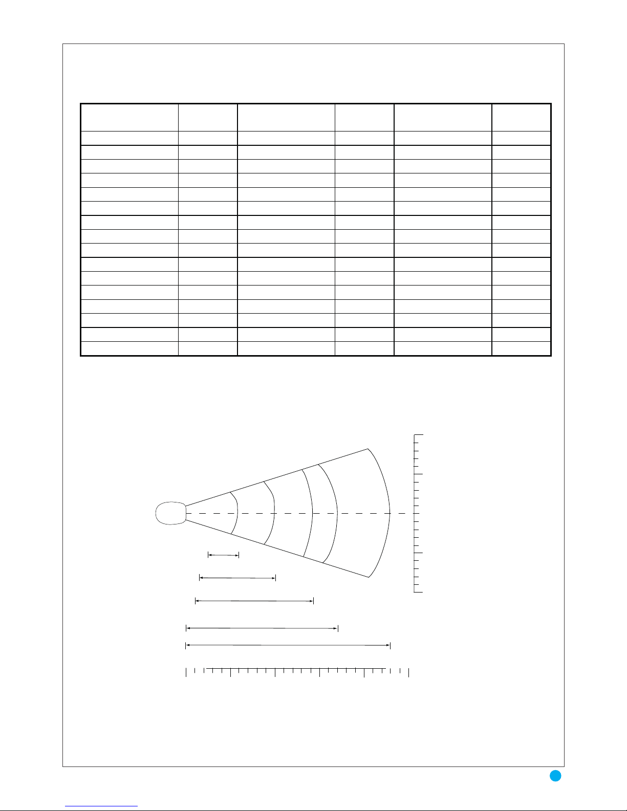
EXTENTED TABLE
Spec. Key
Hexa
Val
Spec. Key
Hexa
Val
Spec. Key
Hexa
Val
F1
80
Back Tab
90
Reserved
A0
F2
81
Back Space
91
Reserved
A1
F3
82
Arrow Right
92
Reserved
A2
F4
83
Arrow Left
93
Reserved
A3
F5
84
Arrow Up
94
Reserved
A4
F6
85
Arrow Down
95
Reserved
A5
F7
86
Alt
96
Reserved
A6
F8
87
Esc
97
Reserved
A7
F9
88
Enter Keypad
98
Reserved
A8
F10
89
Enter Keyboard
99
Reserved
A9
F11
8A
Home
9A
Reserved
AA
F12
8B
Delete
9B
Reserved
AB
Page Up
8C
Ctrl
9C
Reserved
AC
Page Down
8D
End
9D
Reserved
AD
Insert
8E
Reserved
9E
Reserved
AE
Tab
8F
Reserved
9F
Reserved
AF
Note: Typical performance at 73˚ F (23˚ C) on
high quality symbols in normal room light.
in. cm
10 25.4
Auro 2908
W
5 12.7
i
d
t
h
0 0
o
f
1.5"
2.5"
5 mil 6"
7.5 mil
10.0"
F
i
e
5 12.7
l
d
1.0"
10 mil
14.5"
10 25.4
100% UPC
0
17.0"
20 mil
*
23.0"
in.
0 5
10
15
20
34
cm
0
12.7
25.4
38.1
50.8
86.3
Depth of Field
*Minimum distance determined by symbol length and scan angle
DECODE ZONE
33
EXTENTED TABLE & DECIDE ZONE
 Loading...