

auris bordo User Manual

DIGITAL OSCILLOSCOPES
BORDO
User’s Guide
BORDO User’s Guide
2
GETTING SERVICE FROM AURIS
AURIS COMPANY
Web Site http://www.auris.ru/eng
Sales and Service service@auris.ru
Technical Support support@auris.ru
TEL +375 (17) 212 08 16
FAX +375 (17) 278 69 15

BORDO User’s Guide
3
TABLE OF CONTENTS
INTRODUCTION.............................................................................................5
1 DESCRIPTION..............................................................................................5
1.1 APPLICATIONS............................................................................................5
1.2 SPECIFICATION ...........................................................................................5
1.3 CONTENTS OF PACKAGE ..............................................................................7
1.4 SET UP OF OSCILLOSCOPE............................................................................8
1.5 OPERATION THEORY ...................................................................................9
2 USING OSCILLOSCOPE............................................................................10
2.1 ENVIRONMENTAL ......................................................................................10
2.2 GETTING STARTED.....................................................................................10
2.2.1 Unpacking.........................................................................................10
2.2.2 Order to install...................................................................................11
2.2.3 Software installation...........................................................................11
2.3 OPERATING CONTROL DESCRIPTION............................................................12
2.3.1 Software appearance.........................................................................12
2.3.2 Menu commands................................................................................13
2.3.3 Toolbar.............................................................................................17
2.3.4 Screen panel......................................................................................20
2.3.5 Trigger level and zero level scrollbars panel......................................21
2.3.6 Cursors panel information.................................................................21
2.3.8 Keyboard commands..........................................................................22
2.4 USING OSCILLOSCOPE ................................................................................23
2.4.1 Program start....................................................................................23
2.4.2 Preparation for measurement.............................................................24
2.4.3 Active channel selection.....................................................................24
2.4.4 Selection modes for channels vertical deflection.................................25
2.4.5 Timebase mode selection....................................................................26
2.4.6 Using random interleaving sample (RIS) mode...................................27
2.4.7 Time range setting.............................................................................28
2.4.8 Pre/Post trigger functions..................................................................28
2.4.9 Averaging mode of registered signal..................................................28
2.4.10 Trigger setup...................................................................................29
2.4.11 Signal search function......................................................................30
2.4.12 Cursor measurements......................................................................30
2.4.13 Automatic measurements..................................................................31
2.4.14 Spectrum analyzer mode..................................................................34
2.4.15 Accumulation mode..........................................................................36

BORDO User’s Guide
4
2.4.16 Export measured data.....................................................................37
2.4.17 User comments record.....................................................................38
2.4.18 Program settings.............................................................................40

5
INTRODUCTION
The digital oscilloscopes of BORDO are convenient, powerful, inexpensive instruments for acquisition, registration and mathematical processing of various electric signals.
1 DESCRIPTION
1.1 APPLICATIONS
• Registration of high-speed/slow, transient/repetitive signals in wide amplitude
and frequency range.
• Laboratory automation.
• Adjustment of electronic devices, communication equipment.
• Industrial needs.
1.2 SPECIFICATION
Model B–211 B–211A B–221
Number of channels 1 2
Input impedance
1 MΩ
Input capacitance 25 pF
Input coupling AC or DC
Bandwidth 120 MHz 150 MHz 150 MHz
Rise time 2.9 ns 2.3 ns 2.3 ns
Vertical
Vertical resolutions 10 bits
Vertical scale 10 mV/div to 1 V/div
Full scale input ranges 80 mV to 8 V
Vertical accuracy ± 1 % FS
Maximum input voltage 25 V (DC + peak AC) 90 V (DC + peak AC)

BORDO User’s Guide
6
Model B–211 B–211A B–221
Horizontal
Digitizing rate
100 Ms/s — real-time mode,
20 Gs/s — repetitive mode
Time base range 50 ms/div to 5 ns/div
Memory/channel 128 Ks
64 Ks (2-ch mode),
128 Ks (1-ch mode)
Time ranges 1.31 ms to 65 s
655 us to 32 s
(2-ch mode),
1.31 ms to 65 s
(1-ch mode)
Accuracy (best case) 0.0125 %
Trigger
Modes Auto, Normal, Stop, Single shot
Source Internal, External Ch1, Ch2, External
Coupling DC, AC, HF reject
Internal DC,
External DC/AC,
HF reject
Slope Positive or Negative
Bandwidth from 10 Hz to 110 MHz
Delay range
Pre-Trigger (negative delay):
from 0 to 100 % of samples,
Post-Trigger: from 0 to 100 % of samples
Impedance
1 MΩ
External
input
Capacitance
25 pF
Internal Min @ ≤ 10 %, Max @ ≥ 100 % setting input range
External Min @ ≤ 10 mV, Max @ ≥ 5 V
Levels
Control
Settable with resolution of 1 %
of vertical scale coefficient

Description
7
Model B–211 B–211A B–221
Signal Processing
Average Accumulating type, floating-type
Amplitude distribution Absolute, relative scale. Post acquisition
Spectrum analyzer
Frequency range: DC to 150 MHz
Up to 131072 Point FFT.
Spectrum Type: Amplitude, Amplitude dBV, Power,
Power dBm, Phase.
Windowing. Averaging
Advanced Features
Waveform parameter
measurements
Voltage: V
avg
, V
min
, V
max
, V
rms
, Vpp, etc (12 par.)
Time: frequency, period, +pulse width, –pulse width,
duty cycle, rise time, fall time etc (10 par.)
Cursors measurements
Number of cursor: 2
Relative and absolute time and frequency
measurements
Relative and absolute voltage measurements
Autoset Search signal function
Signal file storage
Waveform
storage.
Spectrum storage
. Export (ASCII
data file)
.
16-channels logic analyzer/pattern generator
Optional None
Oscilloscope probes:
1:10, 1:100
Optional
Physical
Dimension
190 × 120 × 22 mm 192 × 126 × 22 mm
1.3 CONTENTS OF PACKAGE
In addition to this User's Guide, the package should include the following
items:
• Digital oscilloscope BORDO card;
• Auris all-in-one compact disc;
• Oscilloscope probes*.
* — Optional.
BORDO User’s Guide
8
1.4 SET UP OF OSCILLOSCOPE
The oscilloscope works in composition PC with the following characteristics:
• Processor: Pentium-166 (or corresponding AMD) and higher;
• RAM not less than 32 Mb;
• Recommended monitor screen resolution 1024 × 768;
• Operating system: Windows 9X/2K/NT/XP.
The oscilloscope is realized as PCI card and can be put into any free slot of the
PCI-bus of the motherboard.
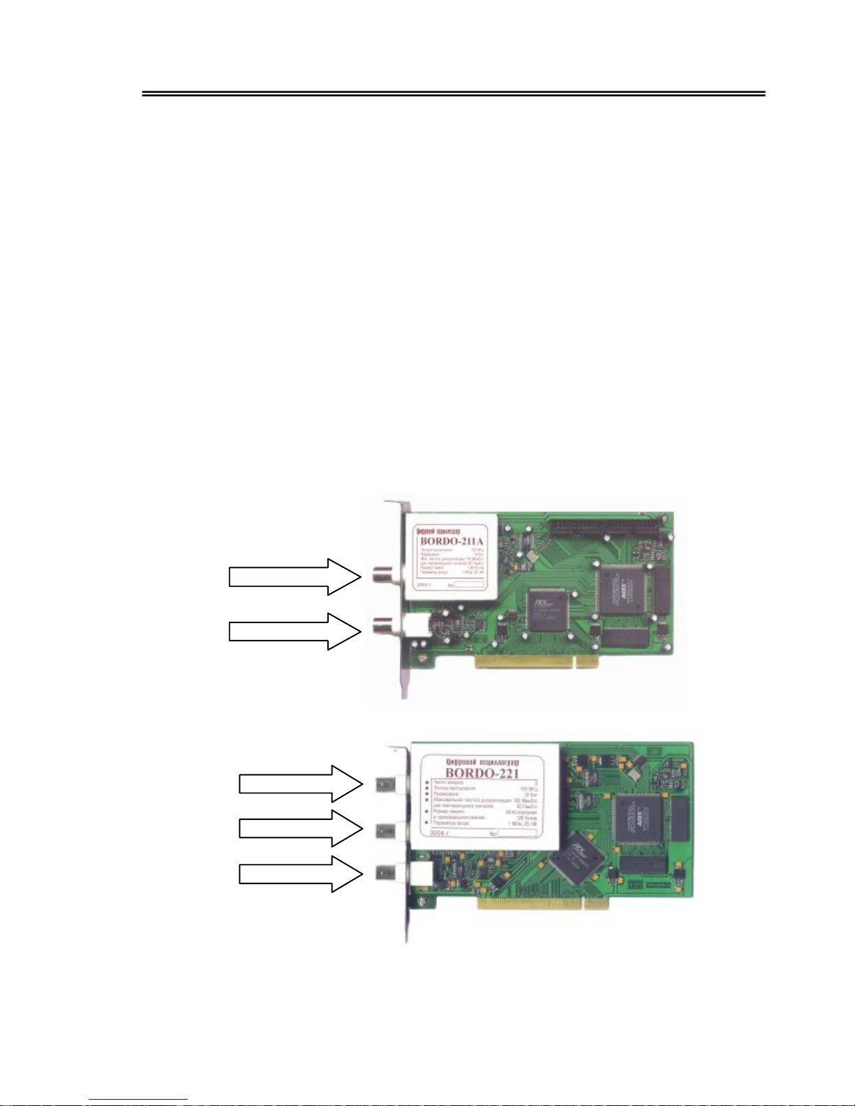
There are thee (B–21x — two) input connectors (standard BNC) on the oscillo-
scope module front panel:
• «IN 1» — channel 1 signal input connector;
• «IN 2» — channel 2 signal input connector (only B–221);
• «TI» — external trigger input connector.
Cards picture see below.
IN
TI
IN1
IN2
TI

Description
9
1.5 OPERATION THEORY
The signal submitted on input of the vertical amplifier is normalized and amplified up to the necessary value. The processed signal feeds ADC inputs, where digital data capture with specified sample rate occurs. Acquired data stored in internal
memory buffer for further transfer into PC memory.
In internal trigger mode channel signals feed to the trigger amplifier in order to
form trigger impulses.
All operating modes of the oscilloscope are controlled by PC, which carries out
reading the information from buffer RAM, its processing and transmission to video
PC for observation on the screen of the monitor.
Direct handle of operation of the oscilloscope is carried out by the program with
the help of graphics manipulator mouse and the keyboard.

10
2 USING OSCILLOSCOPE
2.1 ENVIRONMENTAL
• Temperature:
Operating + 10 to + 35 °C;
Nonoperating – 25 to + 55 °C.
• Humidity
Operating to 80 % RH ≤ 25 °C;
Nonoperating to 98 % RH ≤ 35 °C.
2.2 GETTING STARTED
Before starting to work with the oscilloscope, it is necessary to study all sec-
tions of the present manual closely.
It is necessary to keep oscilloscope card and compact disk not less than 2 hours
per working climatic conditions of application for obtaining correct results of
measurements and for preventing damages.
2.2.1 Unpacking
Your BORDO series card contains electro-static sensitive components that can
easily damaged by static electricity.
Therefore, the card should be handled on a grounded anti-static mat. The opera-
tor should be wearing an anti-static wristband, grounded at the same point as the
anti-static mat.
Inspect the card module carton for obvious damages. Shipping and handling
may cause damage to your module. Be sure there are no shipping and handling
damages on the modules carton before continuing.
After opening the card module carton, extract the system module and place it
only on a grounded anti-static surface with component side up.
Again, inspect the module for damages and extraneous subjects on card, to
check up cleanness of plugs and solder pads. Solder pads wipe with spirit moistened cotton wool at pollution.

Getting started
11
2.2.2 Order to install
Mount card in PC only with switched off power supply of PC. It is forbidden to
make great efforts at mounting of card in the computer slot in order to prevent
breakage of the motherboard of PC or oscilloscope card.
Order to install of oscilloscope card:
1. Switch off power supply of PC.
2. Open (to remove) casing of PC.
3. Remove (if necessary break out) the metal bracket of the free PCI slot of PC.
4. Carefully insert oscilloscope card into the free slot and fix the front panel from
above with a screw (default of this condition can put the system out of func-
tion).
5. Close casing of PC.
It is necessary that the potentials of cases of all instruments are set equal, during
combining measurements together with other instruments or including of card in
composition of measuring equipments.
It is necessary to connect protective grounding of computer before all subsequent connections and to disconnect after all detachment
2.2.3 Software installation
Switch on PC and load operating system.
The operating system will detect the new device and will suggest installing its
driver. For installation of the driver, it is necessary to select B2xx.inf file, which is
placed in a folder \Driver\ on the compact disc. The system will install the necessary driver depending on the type of operating system installed on PC.
Install the software from AURIS compact disc, following the instructions of the
install program.
After start of oscilloscope program the appearance of the initial control panel of
the oscilloscope must be checked on the screen. Then press on the keyboard F9 key
or with the help of the mouse the button "Start" on the screen. In case of correct
installation, the horizontal ray of the scanning should appear without additional
reports on the screen of the oscilloscope.
Attention! The program of the digital oscilloscope allows controlling simultaneously several oscilloscopes BORDO installed in one computer.

12
2.3 OPERATING CONTROL DESCRIPTION
2.3.1 Software appearance
After start of the application, the main application window appears on the
screen. Main window’s screenshot is shown on fig. 2.1. The figure contains paragraph’s references with controls description.
The main window contains following items: the three upper lines are (up-todown): window title, menu bar and toolbar. Oscilloscope’s working screen is
placed under the toolbar. Trigger level scrollbar and zero level scrollbars are
placed to the right from working screen. Screen panel is on the left front the work-
ing screen. Under the working screen, there is information cursors panel. The
status bar located at the very bottom closes a front panel.
Window title and menu bar a standard parts of any windows application. Window title contains the applications and current data names.
 Loading...