

AURATON S14 User Manual
User manual
www.auraton.pl
S14
dla oprogramowania w ver. F03 oraz F0A
AURATON S14
AURATON S14 is a modern processor-based controller intended for work
with central heating (CH) and hot domestic water (HDW) circulating
pumps. The controller may work with a boiler stove fireplace in a CH
system and with a forced draft coal or fine c oal fired CH stove.
Description of the display
1
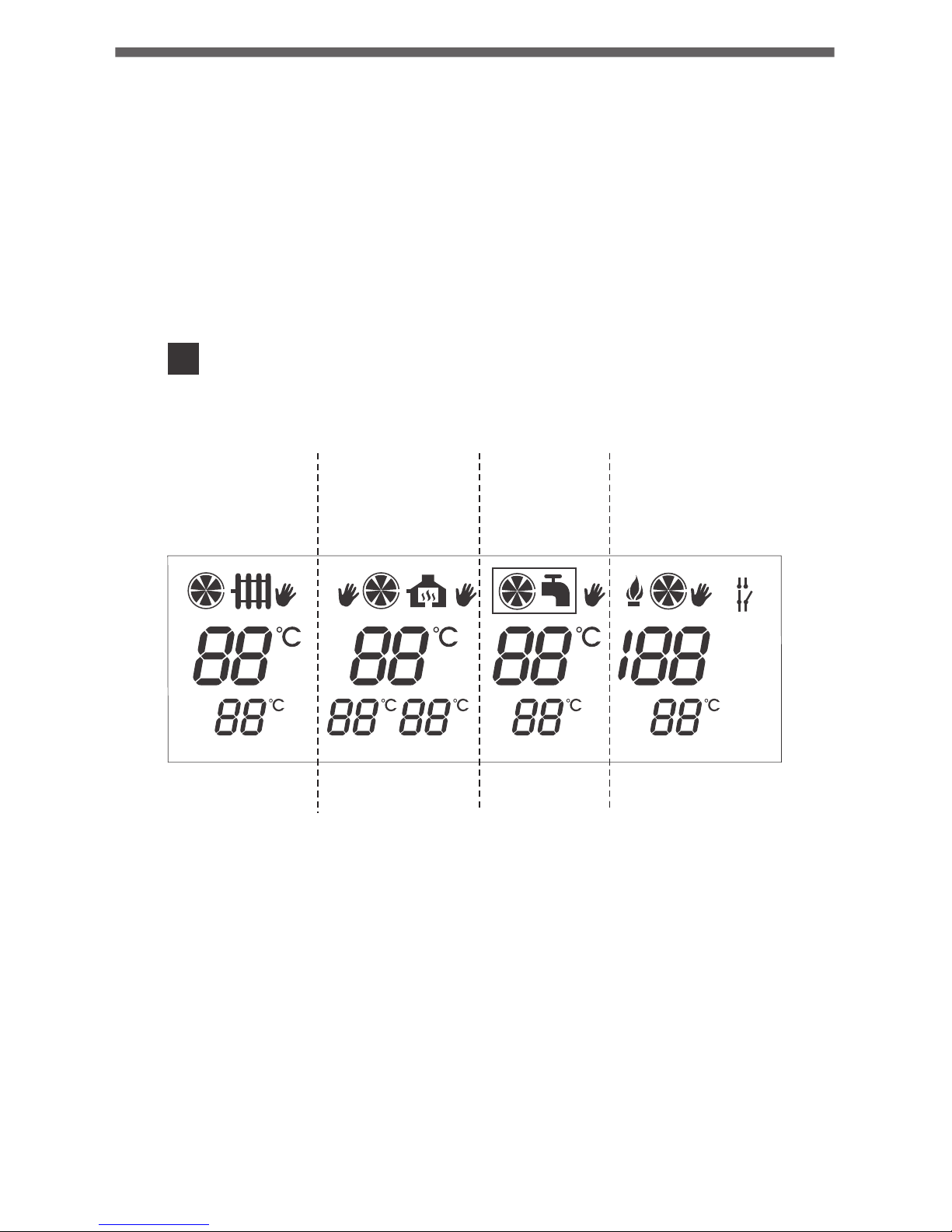
The display of the AURATON S14 controller is divided into four parts.
Each part corresponds to a separate device supported by the controller:
Part A: Control of the central heating (CH) pump,
Part B: Control of the central heating (CH) pump, the automatically
reset actuator, or the second central heating pump (in the
fireplace circuit),
Part C: Control of the hot domestic water (HDW) circulating pump,
Part D: Control of the fan (blower).
ON
OFF
S MIN
STOP LO
STOP HI
AUTO
%
A B C D
2
1
6
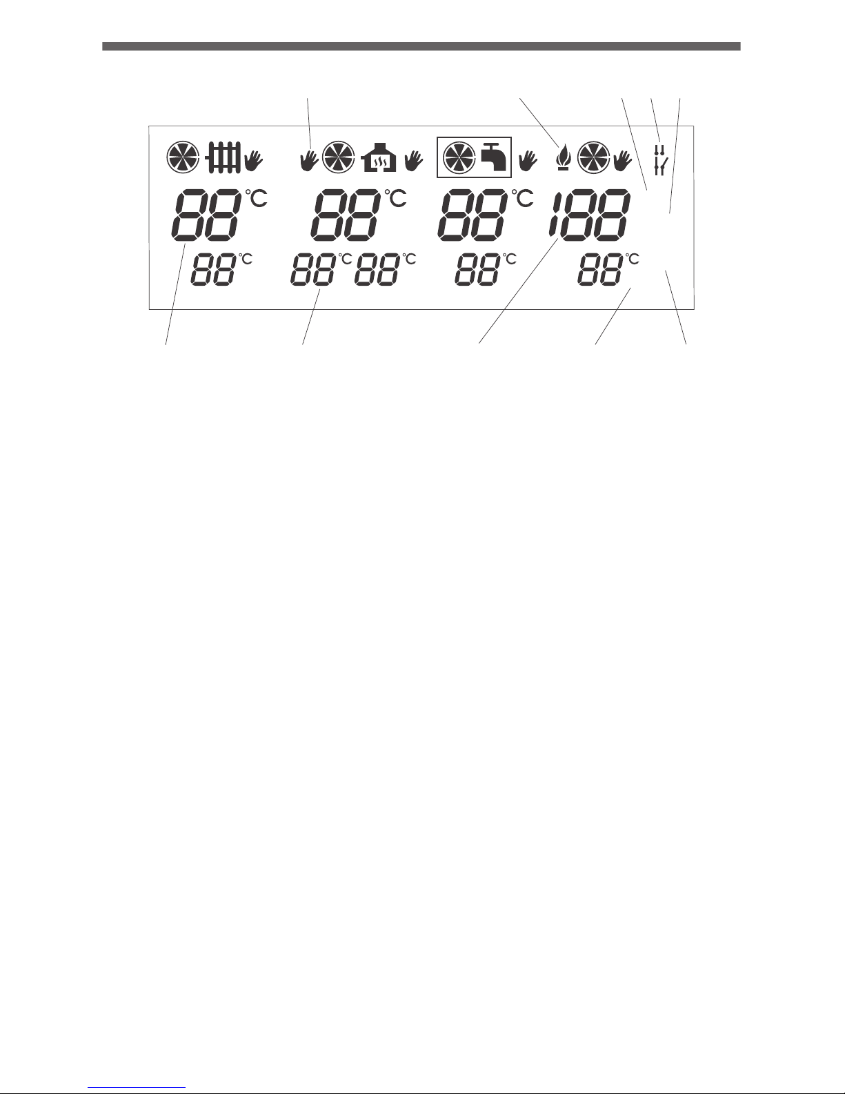
1. Temperature measured by individual sensors,
2. User's setting,
3. Counted operation time of the fan and the duration of the interval
between the blow-throughs,
4. Indicator of extinguished fire in the furnace,
5. Indicator of emergency shutdown of the fan,
6. Indicator of manual activation of the device ,
7. Indicator of ignition,
8. Indicator of fan power percentage value,
9. Indicator of forced operation (of the CH pump),
10. Indicator of sustained fire in the furnace.
3
1
6
7
8
9
10
3
4 52
ON
OFF
S MIN
STOP LO
STOP HI
AUTO
%
1. Temperature measured by individual sensors,
2. User's setting,
3. Counted operation time of the fan and the duration of the interval
between the blow-throughs,
4. Indicator of extinguished fire in the furnace,
5. Indicator of emergency shutdown of the fan,
6. Indicator of manual activation of the device ,
7. Indicator of ignition,
8. Indicator of fan power percentage value,
9. Indicator of forced operation (of the CH pump),
10. Indicator of sustained fire in the furnace.
General comments
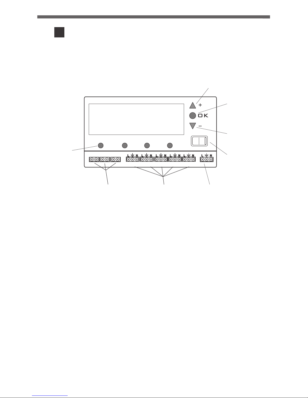
1. Buttons "A, B, C, D" for configuration of individual settings,
2. Terminals for connecting temperature sensors (SR1 through SR3),
3. Terminals for connecting actuators (OUT1 through OUT5),
4. Terminals for connecting the power supply,
5. "+" (plus) button - higher value,
6. "OK" button - approval,
7. "-" (minus) button - lower value,
8. Main power supply switch.
1. Before connecting the cables to the controller, remove the protective
plugs by cutting them off.
2. Only one sensor is provided (with an approx. 2.5 m long cable). If an
expanded functionality of the controller is required, additional
temperature sensors must be bought (option). If the length of the
cable is inadequate, a sensor with an approx. 15 m long cable can be
purchased.
4
1
2
3 4
5
6
7
8
0
I
A B C D
SR1 SR2 SR3
OUT1 OUT2 OUT3 OUT4 OUT5 IN
Description of buttons
and cable terminals
2
NOTE: In order to access the cable terminals, remove the front cover.
3
Description of the controller working
in a CH circuit (part A of the display)
The controller also has the GUARD functions which prevents the stalling
process in the rotor of the pump when it is not in use. Also, a built in
processor starts the pump for 30 seconds after the heating season is over.
In order for the system to work after the heating season, the controller
must be switched on.
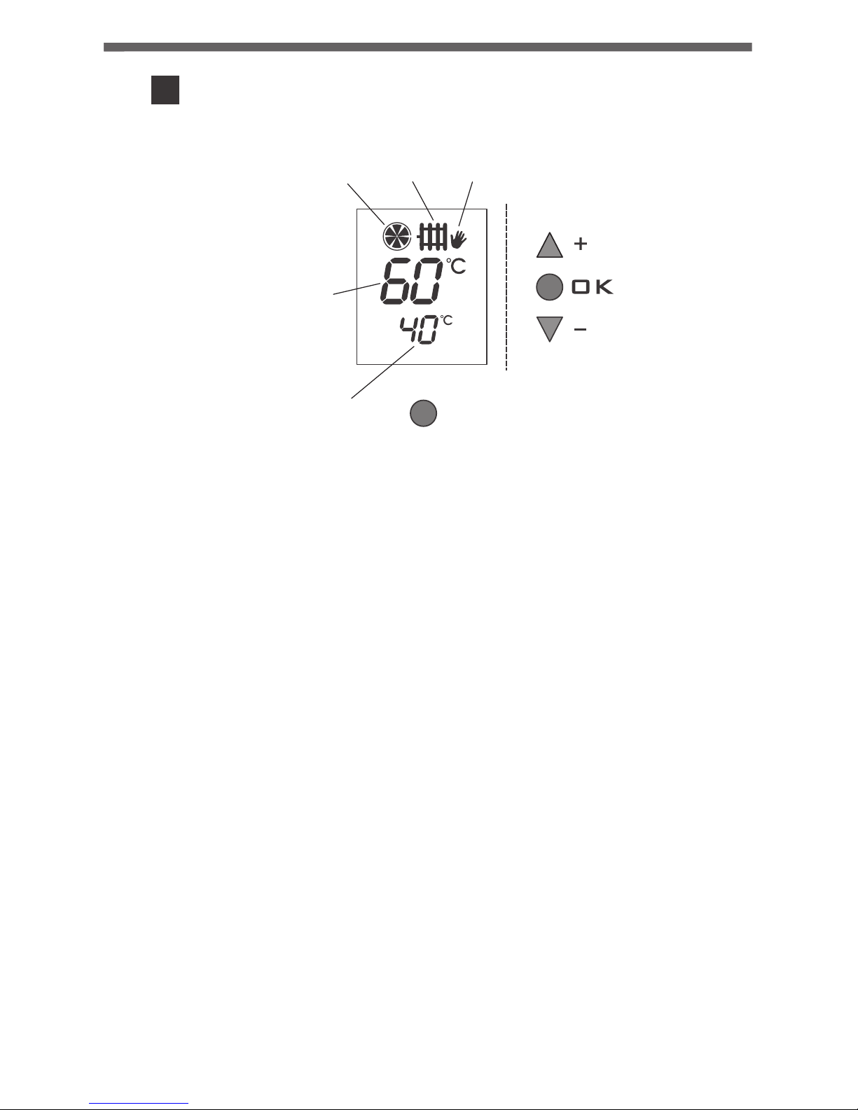
1. CH pump operation indicator,
2. CH pump's sensor indicator,
3. Manual mode operation indicator,
4. Current temperature on the CH sensor (SR1),
5. Set temperature indicator.
The controller-pump assembly forces the water to circulate in a CH
system with a coal-fired boiler or a gas boiler without a system controlling
the operation of the pump. The controller's sensor measures the
temperature of the water on the supply side of the CH system.
In a CH system with a coal-fired boiler, the controller switches off the
circulation pump after the flame in the boiler is extinguished. Pumping of
water is not recommended when the flame is extinguished because the
air draft into the chimney causes faster cooling of the water in the boiler
faster than in the radiators. The optimum temperature can be set on the
controller's scale (most often approx. 40°C).
In a CH system with a gas boiler, the temperature must be lower than the
temperature set on the CH boiler's thermostat. If the temperature is set
above the dew point, it prevents condensation in the boiler during the
heating of the water in the CH system.
5
3
Description of the controller working
in a CH circuit (part A of the display)
The controller also has the GUARD functions which prevents the stalling
process in the rotor of the pump when it is not in use. Also, a built in
processor starts the pump for 30 seconds after the heating season is over.
In order for the system to work after the heating season, the controller
must be switched on.
A
1
2
3
4
5
1. CH pump operation indicator,
2. CH pump's sensor indicator,
3. Manual mode operation indicator,
4. Current temperature on the CH sensor (SR1),
5. Set temperature indicator.
The controller-pump assembly forces the water to circulate in a CH
system with a coal-fired boiler or a gas boiler without a system controlling
the operation of the pump. The controller's sensor measures the
temperature of the water on the supply side of the CH system.
In a CH system with a coal-fired boiler, the controller switches off the
circulation pump after the flame in the boiler is extinguished. Pumping of
water is not recommended when the flame is extinguished because the
air draft into the chimney causes faster cooling of the water in the boiler
faster than in the radiators. The optimum temperature can be set on the
controller's scale (most often approx. 40°C).
In a CH system with a gas boiler, the temperature must be lower than the
temperature set on the CH boiler's thermostat. If the temperature is set
above the dew point, it prevents condensation in the boiler during the
heating of the water in the CH system.
3.2.1. Switching the controller on
ut the switch n the "I" position. After the controller is switched
on, all segments of the display are lit for about 2 seconds and the software
version is displayed. Then the " symbol, the current sensor
temperature (4), and the set temperature (5) are shown on the display.
P i
"
[butt]
grzej]
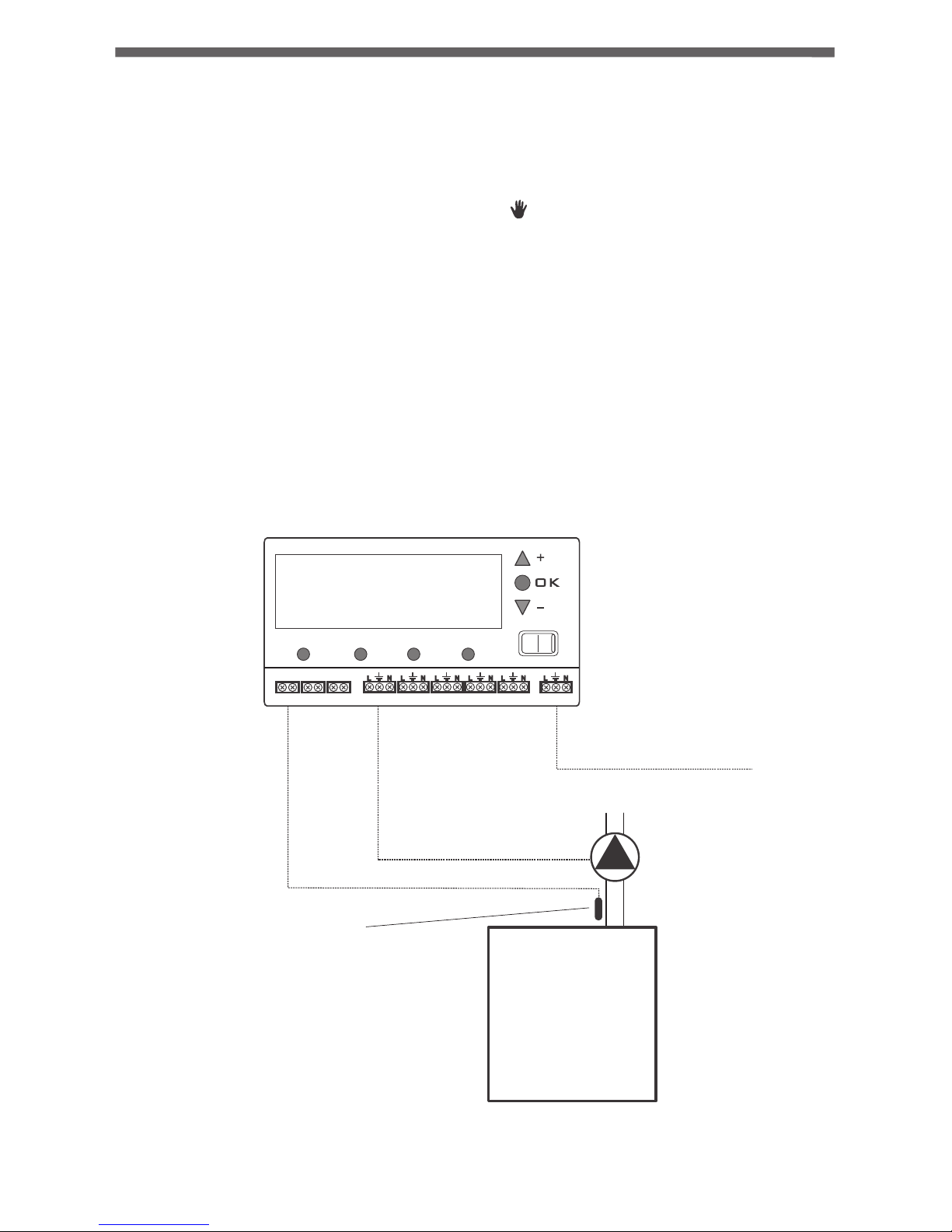
3.1.3. Connecting the power supply cable of the pump
In the controller, the pump's cable must be connected to the OUT1
terminal. In the pump, connect the green or yellow-green wire
(grounding or protective zero) to the " " terminal and connect the blue
wire to the "N" terminal. Connect the brown wire to the "L" terminal.
3.1. Installation
3.1.1. Mounting the controller
The controller must be mounted on a wall or another support using two
screws (the concrete anchors with screws are delivered with the
controller). The cables extending from the controller must be fixed to the
wall with cable clips.
3.1.2. Mounting the sensor
Before installing the cables, remove the protective plugs by cutting them
off. In the controller, connect the temperature sensor to the SR1
terminals. Then install the sensor on an uncovered outlet pipe connected
to the CH boiler (as close to the boiler as possible).
NOTE: If a coal-fired boiler and a gas-fired boiler work in the same CH
system, the sensor should be installed in a location where the two
outlets merge and must be insulated.
3.1.4. Connection check
Check if the wire is connected properly and fix the lid of the pump motor's
compression box with screws.
3.1.5. Connecting the controller
NOTE: The wires and cables may be connected only when the
power supply is cut off.
After the wires are secured to prevent accidental ripping, connect the
power supply cable to a 230V AC/50 Hz power outlet with a grounding
pin.
NOTE: The ambient temperature in the place where the controller
is installed must not exceed 40°C.
3.2. Operation of the controller
0
I
3.2.3. Changing the temperature
Press the "A" button under the temperature setting. The digits begin to
blink and indicate the value of the current setting. Using the "+" (increase)
or "-" (decrease) button, set the desired temperature. After the
temperature value is set, approve it (within 10 seconds) by pressing the
"OK" button. Otherwise, the changed value will not be saved and the
controller will return to the previous setting.
3.2.4. Changing the hysteresis
Press the "A" button under the temperature setting. The digits begin to
blink and indicate the value of the current setting. Display the hysteresis
setting (HI) by pressing the "A" button again. Using the "+" or "-" button,
set the required hysteresis value in the range of 2°C to 10°C (with a 2°C
increment). After the value is set, approve it (within 10 seconds) by
pressing the "OK". Otherwise, the changed setting will not be saved and
the controller will return to the previous setting.
Example: If the temperature setting is 40°C and the hysteresis is 4°C, the
pump will start at 42°C and will stop at 38°C.
3.2.5. Changing the forced pump operation mode
Press the "A" button under the temperature setting. The digits begin to
blink and indicate the value of the current setting. Display the hysteresis
setting (HI) by pressing the "A" button again. After you press the "A"
button one more time, the value of 85°C will be displayed in the
temperature section and on the right side of the display the symbol of
forced pump operation ( ). Za pomocą przycisku „+” lub „–” will be
shown. Using the "+" or "-" button, select a setting where, after the
temperature exceeds 85°C, the pump is in continuous operation ( ) or
shuts down ( ).
After the pump operation mode is set, approve it (within 10 seconds) by
pressing the "OK" button. Otherwise, the changed setting will not be
saved and the controller will return to the previous setting.
^
3.2.6. Automatic operation
After this operation mode is set, the controller starts and stops the pump
depending on the set temperature. In the CH system, the pump is started
when the temperature in the location of the sensor exceeds the set value
and stopped when the temperature drops below the value set in the
controller, taking into account the hysteresis.
3.2.2. Description of the display
The top part of the display (4) shows the current temperature of the
sensor while the bottom part (5) shows the set temperature. Movement
of the blades on the indicator (1) indicates operation of the CH pump.
!

76
3.2.3. Changing the temperature
Press the "A" button under the temperature setting. The digits begin to
blink and indicate the value of the current setting. Using the "+" (increase)
or "-" (decrease) button, set the desired temperature. After the
temperature value is set, approve it (within 10 seconds) by pressing the
"OK" button. Otherwise, the changed value will not be saved and the
controller will return to the previous setting.
3.2.4. Changing the hysteresis
Press the "A" button under the temperature setting. The digits begin to
blink and indicate the value of the current setting. Display the hysteresis
setting (HI) by pressing the "A" button again. Using the "+" or "-" button,
set the required hysteresis value in the range of 2°C to 10°C (with a 2°C
increment). After the value is set, approve it (within 10 seconds) by
pressing the "OK". Otherwise, the changed setting will not be saved and
the controller will return to the previous setting.
Example: If the temperature setting is 40°C and the hysteresis is 4°C, the
pump will start at 42°C and will stop at 38°C.
3.2.5. Changing the forced pump operation mode
Press the "A" button under the temperature setting. The digits begin to
blink and indicate the value of the current setting. Display the hysteresis
setting (HI) by pressing the "A" button again. After you press the "A"
button one more time, the value of 85°C will be displayed in the
temperature section and on the right side of the display the symbol of
forced pump operation ( ). Za pomocą przycisku „+” lub „–” will be
shown. Using the "+" or "-" button, select a setting where, after the
temperature exceeds 85°C, the pump is in continuous operation ( ) or
shuts down ( ).
After the pump operation mode is set, approve it (within 10 seconds) by
pressing the "OK" button. Otherwise, the changed setting will not be
saved and the controller will return to the previous setting.
^
^.
^
3.2.6. Automatic operation
After this operation mode is set, the controller starts and stops the pump
depending on the set temperature. In the CH system, the pump is started
when the temperature in the location of the sensor exceeds the set value
and stopped when the temperature drops below the value set in the
controller, taking into account the hysteresis.
3.2.2. Description of the display
The top part of the display (4) shows the current temperature of the
sensor while the bottom part (5) shows the set temperature. Movement
of the blades on the indicator (1) indicates operation of the CH pump.
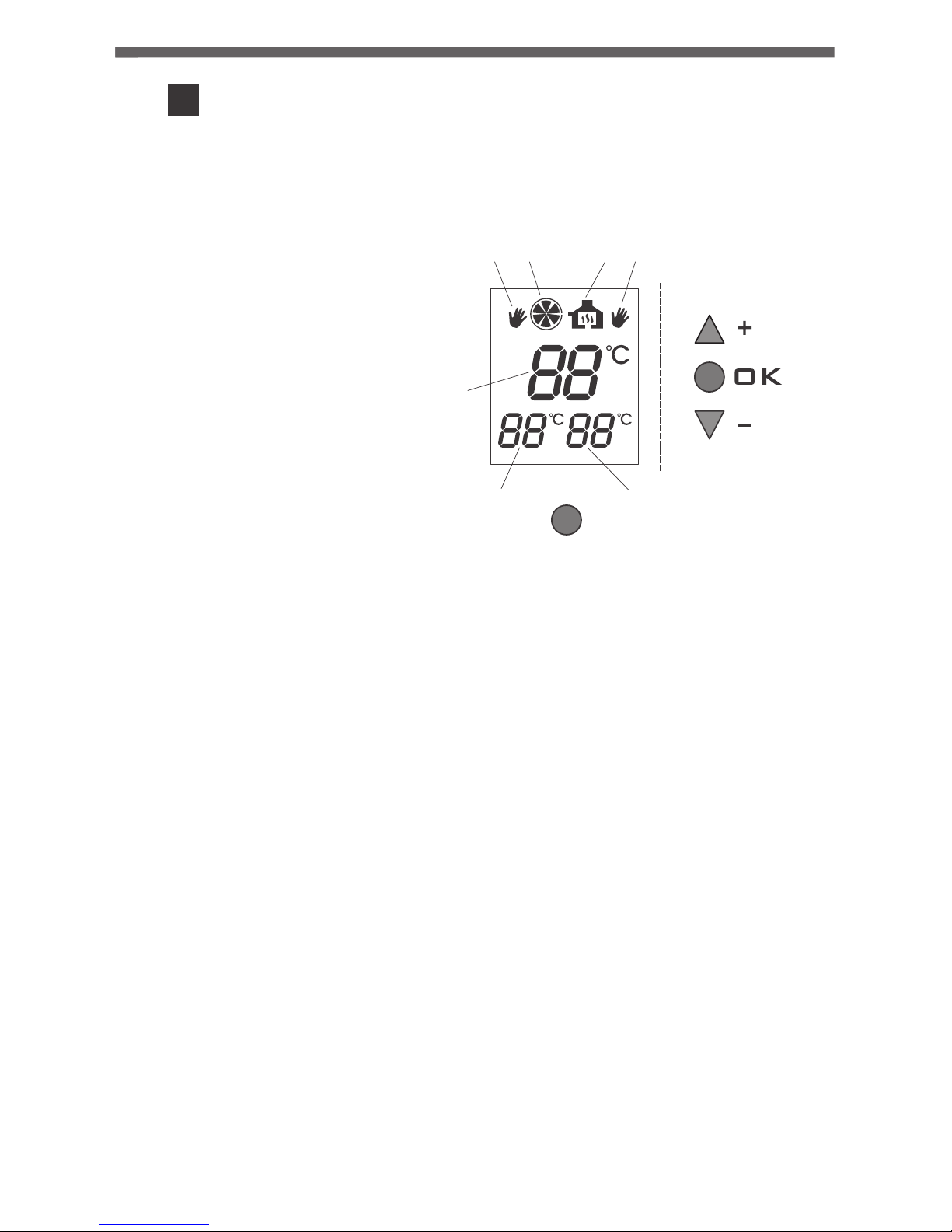
1. Current temperature on the
CH sensor (SR2)
2. Indicator of the set CH
temperature in the
fireplace circuit,
3. Indicator of the set
temperature of the
automatically reset
actuator or the second CH
pump,
4. Indicator of manual activation
of the CH pump,
5. CH pump operation indicator,
6. Indicator of operation of a tee valve or the second CH pump,
7. Indicator of manual activation of a tee valve or the second CH pump.
3.2.7. Manual mode - continuous operation
In order to manually switch on the circulating pump (regardless of the
current temperature at the SR1 (CH) sensor), press the "A" button and
hold it pressed for 3 seconds.
The display will show the hand symbol " " (3). If you wish to switch off
the pump's manual operation, press the "A" button again and hold it
pressed for 3 seconds.
NOTE: When only the SR1 sensor is connected, the remaining functions
of the controller are inactive, i.e. there is no indication of operation of
CH pumps in the fire place circuit and of the control of the pump in the
HDW circuit.
[h]
3.3. Diagram of connection of the controller with
the pump at the CH boiler
0
I
A B C D
SR1 SR2 SR3
OUT1 OUT2 OUT3 OUT4 OUT5 IN
CH
boiler
Pump
230V
mains power supply
Temperature sensor
(fix with a band)
4
Description of a controller working with
a CH pump and an automatically reset
actuator, or with a second CH pump -
a fireplace boiler stove circuit
(part B of the display)
AURATON S14 in a circuit with a boiler stove fireplace uses two control
outputs:
one for the water pump in the fireplace circuit;
ź
one for an actuated valve or the second pump, which is required for
ź
proper cooperation between the boiler stove fireplace with the CH
circuit.
After the power supply is switched on, temperature in the water jacket of
the boiler stove fireplace is measured (with the digital sensor); the
temperature signal can be divided into two independent channels.
Depending on the temperature of water in the fireplace circuit, the
controller automatically starts or stops the CH pump of the fireplace and
starts the valve or the second pump.
The AURATON S14 controller also has the GUARD functions which
prevents the stalling process in the rotor of the pump when it is not in use.
After the heating season, AURATON S14 automatically starts the pump
for 30 seconds every 14 days.
In order for the system to work after the heating season, the controller
must be switched on at all times.
98
1. Current temperature on the
CH sensor (SR2)
2. Indicator of the set CH
temperature in the
fireplace circuit,
3. Indicator of the set
temperature of the
automatically reset
actuator or the second CH
pump,
4. Indicator of manual activation
of the CH pump,
5. CH pump operation indicator,
6. Indicator of operation of a tee valve or the second CH pump,
7. Indicator of manual activation of a tee valve or the second CH pump.
4
Description of a controller working with
a CH pump and an automatically reset
actuator, or with a second CH pump a fireplace boiler stove circuit
(part B of the display)
4
6
7
1
5
B
2
3
AURATON S14 in a circuit with a boiler stove fireplace uses two control
outputs:
one for the water pump in the fireplace circuit;
ź
one for an actuated valve or the second pump, which is required for
ź
proper cooperation between the boiler stove fireplace with the CH
circuit.
After the power supply is switched on, temperature in the water jacket of
the boiler stove fireplace is measured (with the digital sensor); the
temperature signal can be divided into two independent channels.
Depending on the temperature of water in the fireplace circuit, the
controller automatically starts or stops the CH pump of the fireplace and
starts the valve or the second pump.
The AURATON S14 controller also has the GUARD functions which
prevents the stalling process in the rotor of the pump when it is not in use.
After the heating season, AURATON S14 automatically starts the pump
for 30 seconds every 14 days.
In order for the system to work after the heating season, the controller
must be switched on at all times.
 Loading...