

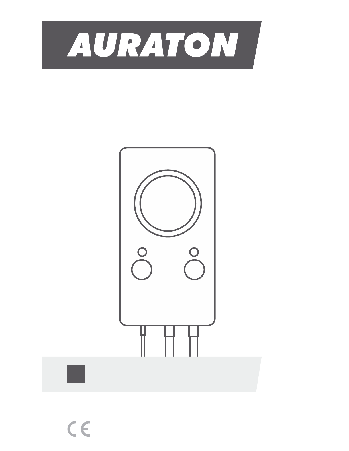
AURATON S08 User Manual
S08
USER MANUAL
EN
www.auraton.pl

AURATON S08
Bifunctional central heating (CH)
or domestic hot water (DHW) pump controller
Can be used as a CH pump controller.
Pumping of water is not recommended when the flame is extinguished
because the air draft into the chimney causes faster cooling of the water
in the boiler faster than in the radiators.
The optimum temperature can be set on the controller's display (most
often 40 °C).
In a CH system with a gas boiler, the temperature set on the controller
must be lower than the temperature set on the CH boiler. If the
temperature is set on the controller above the dew point, it prevents
condensation in the boiler during the heating of the water in the
CH system.
AURATON S08 can be used for automatically switching on and off
circulation pumps depending on the temperature. The controller-pump
assembly forces the water to circulate in the central heating system with a
coal-fired boiler or a gas boiler. The controller's sensor measures the
temperature of the water on the supply side of the CH system. In a CH
system with a coal-fired boiler, the controller switches off the circulation
pump after the flame in the boiler is extinguished.
The range of settings for the CH pumps is from 20 °C to 90 °C.
Can be used as a DHW pump controller.
In domestic hot water (DHW) systems, the controller-pump assembly
forces circulation of water in DHW systems with coal-fired and gas-fired
boilers without systems controlling the operation of the pump.
The controller’s sensor measures the water temperature in the HDW
tank.
AURATON S08 can be used for automatically switching on and off
circulation pumps depending on the temperature.
The range of settings for the HDW pumps is from 20 °C to 90 °C.
The hysteresis (the difference between the switch on temperature and
the shut down temperature) can be set in the range of 2 to 8 °C.
In HDW systems, the controller maintains constant temperature of water
in the tank or in the HDW circuit.
Installation
Mounting the sensor:
ź Then install the sensor on an uncovered outlet pipe connected to the
CH boiler (as close to the boiler as possible).
ź Press the sensor against the tube using a clamp.
Operation in the CH mode.
ź It is recommended to wrap the boiler pipe from the boiler to the
sensor with an insulation material.
ź Connect the brown conductor (phase conductor) to the (L) terminal.
ź Connect the yellow or yellow-green conductor (ground or protective
neutral grounding) to the ( ) terminal.#
ź After the wires have been secured to prevent accidental pulling,
connect the power supply cable to a 230 V/50 Hz power outlet.
Connecting the controller:
NOTE: The sensor must not be immersed in liquids or installed at
flue gas outlets to the stack.
Mounting the controller:
ź Connect the blue conductor (zero conductor) to the (N) terminal.
ź The controller must be mounted on a wall or another support using
two screws (the concrete anchors with screws are delivered with the
controller).
ź If a coal-fired boiler and a gas-fired boiler work in the same CH
system, the sensor should be installed in a location where the two
outlets merge and must be insulated.
Operation in the DHW mode.
Connecting the power supply cable to the pump:
ź Install the sensor in the HDW tank.
ź The cables extending from the controller must be fixed to the wall.

3
Installation
Mounting the sensor:
ź Then install the sensor on an uncovered outlet pipe connected to the
CH boiler (as close to the boiler as possible).
ź Press the sensor against the tube using a clamp.
Operation in the CH mode.
ź It is recommended to wrap the boiler pipe from the boiler to the
sensor with an insulation material.
ź Connect the brown conductor (phase conductor) to the (L) terminal.
ź Connect the yellow or yellow-green conductor (ground or protective
neutral grounding) to the ( ) terminal.#
ź After the wires have been secured to prevent accidental pulling,
connect the power supply cable to a 230 V/50 Hz power outlet.
Connecting the controller:
NOTE: The sensor must not be immersed in liquids or installed at
flue gas outlets to the stack.
Mounting the controller:
ź Connect the blue conductor (zero conductor) to the (N) terminal.
ź The controller must be mounted on a wall or another support using
two screws (the concrete anchors with screws are delivered with the
controller).
ź If a coal-fired boiler and a gas-fired boiler work in the same CH
system, the sensor should be installed in a location where the two
outlets merge and must be insulated.
Operation in the DHW mode.
Connecting the power supply cable to the pump:
ź Install the sensor in the HDW tank.
ź The cables extending from the controller must be fixed to the wall.
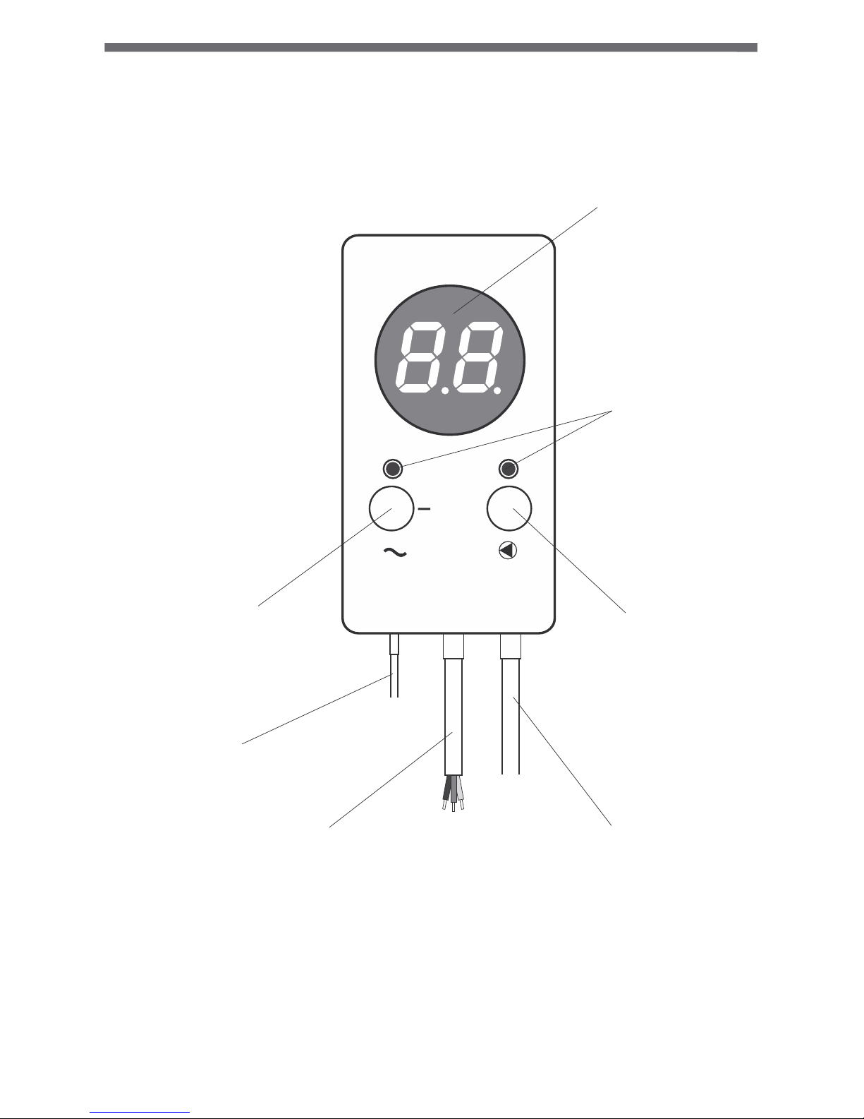
Description of the controller
+
Temperature,
settings display, etc.;
Operation
indicator
lights;
Function button
/network switch;
Function button
/operation modes;
Temperature
sensor;
Power supply
wire
Pump control
output;
First start
2) Software version (e.g. 1.0).
– DHW pump
4) Current temperature of the sensor.
On the left side under the display there is the network switch button ( ). ~
Hold the button for 2 seconds to switch the controller on or off. When the
controller is on, the LED is illuminated red and when it is off, the LED is
illuminated green.
After the controller is switched on, the following sequence of information
is shown on the display:
– CH pump
The sensor is ready to set the appropriate operating temperature.
3) Controller operation modes.
1) Display test (all segments are on).
The temperature value will then blink for 5 seconds on the display. The
appropriate temperature can then be set using the ( – ) or ( + ) button.
After the setting has been performed, the controller automatically stores
this value and the display shows the current sensor temperature.
The temperature setting function can be activated by briefly pressing the
left or right button.
Setting the temperature
The change of the operation mode is saved automatically.
The controller can be set in one of two operation modes.
In order to check the controller’s operation mode, press and hold both
the (–) and the (+) button for 2 seconds. The following information will be
shown on the display:
– controller in the CH pump operation mode;
– controller in the DHW pump operation mode.
The operation mode can be changed by simultaneously pressing and
holding both the (–) and the (+) button for 4 seconds. The display will
show the blinking symbols “ ” or “ ”. When this informationCoO CuU
is displayed, you can change the mode by pressing the (–) or (+) button.
Setting the controllers' mode of operation.
 Loading...