

AURATON S03 RTH User Manual
OFF
ON
IN
OUT
ALARM
RESET
S03 RTH
USER’S MANUAL
EN

2
Wireless central heating pump controller
AURATON S03 RTH
The AURATON S03 RTH controller is tended for wireless control of a
central heating (CH) pump.
Before you start using the controller, please read this instruction
carefully.

3
APPLICATION
AURATON S03 RTH is intended for automatically switching on and off
circulation pumps depending on the temperature. The controllerpump assembly forces the water to circulate in the central heating
system with a coal-fired boiler or a gas boiler. The controller's sensor
measures the temperature of the water on the supply side of the CH
system. In a CH system with a coal-fired boiler, the controller switches
off the circulation pump after the flame in the boiler is extinguished.
Pumping of water is not recommended when the flame is extinguished
because the air draft into the chimney causes faster cooling of the
water in the boiler faster than in the radiators. The optimum
temperature can be set on the controller's scale (most often 40 °C).
In a CH system with a gas boiler, the temperature set on the controller
must be lower than the temperature set on the CH boiler. If the
temperature is set on the controller above the dew point, it prevents
condensation in the boiler during the heating of the water in the CH
system.
The AntyStop (AS) system installed in the Auraton S03 RTH controller
prevents seizure of the rotor of an unused pump. Also, a built in
processor starts the pump every 14 days for 30 seconds after the
heating season is over. In order for the system to work after the heating
season, the controller must be switched on with the AS function active
at all times.
AntyStop system
4
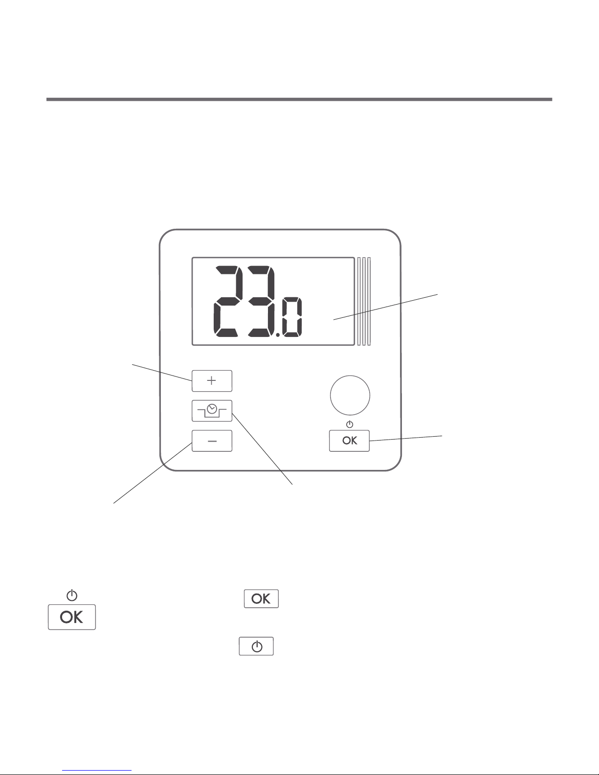
Description of the controller
LCD display
a temperature
increase button
On the front part of the enclosure there is a backlit LCD display and
four function buttons.
a button for the reduction
of the programmed
pump shutdown temperature mode
/ AntyStop mode
a confirmation
or controller
on/off button
a temperature
decrease button
ź by pressing the button for a short time, you can
confirm the temperature setting
ź by holding the button, you can switch the
controller on/off
5
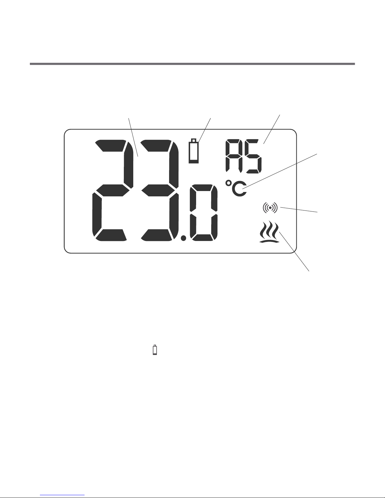
Display
1. Temperature
In the normal operation mode, the controller displays the
temperature in the room where it is installed.
2. Discharged battery ( )
The indicator is displayed when the permissible minimum battery
voltage level is exceeded. The battery must then be replaced as
soon as possible.
NOTE: In order to maintain the controller settings, the battery
replacement should take not more than 30 seconds.
1 2
3
4
5
6

3. AntyStop mode activation indicator
This mode prevents seizing of the rotor of an unused pump.
4. Temperature unit ( )
This indicates that the temperature is displayed in degrees
Celsius.
5. Activated pump indicator ( )
A pictogram that indicates the operating status of the pump. It is
displayed when the controlled device is switched on.
6. Transmission symbol ( )
Indicates communication with the receiver.
6
7
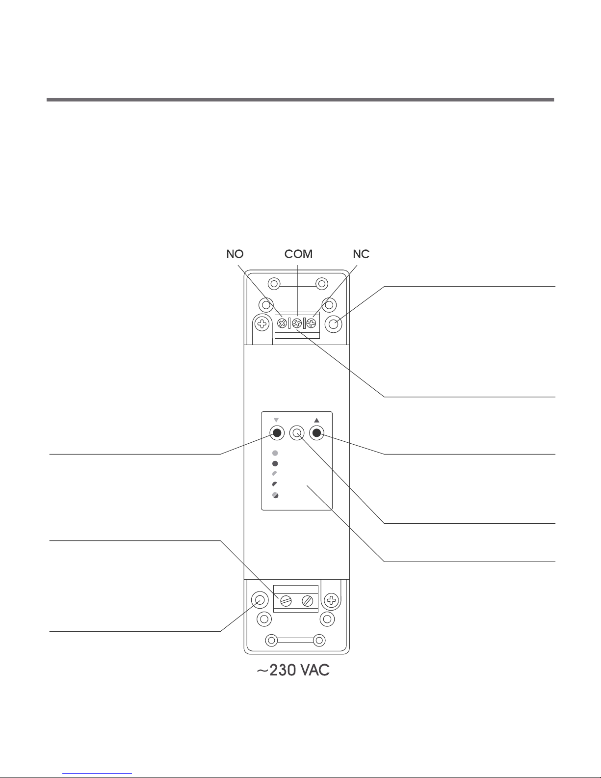
Description of the RTH receiver
The RTH receiver works with the wireless AURATON S03 controller. It
can work at the load equal to 16 A.
The receiver is installed at the CH pump.
OFF
ON
IN
OUT
ALARM
RESET
cable fixture
control connection terminal
button for unpairing devices
button for pairing devices
with the receiver
diode indicating
operation of the device
cable fixture - power supply
connection terminal
approx. 230 V AC
key/description
hole for the screw
fixing the receiver to the wall
hole for the screw
fixing the receiver to the wall

8
The diode is illuminated green - the operating device is
off (the COM and NC contacts are closed).
The diode is illuminated red - the operating device is on
(the COM and NO contacts are closed).
The diode is blinking green - the receiver is waiting for the
device to be paired - (chapter “Paring of a wireless
controller with the receiver”).
The diode is blinking red - the repeater is waiting for a
device to unpair - (chapter: “Unpairing the controller
from the receiver”).
The diode is blinking red and green alternately:
ALARM - the receiver’s connection with one of the paired
devices is broken - (chapter: “Special
situations”).
RESET - the receiver unpairs all the previously paired
devices - (chapter: “Unpairing all devices paired
with the receiver”).
Key - description of diode signaling in the receiver
 Loading...