

AURATON 3021 RTH Owner's Manual
OFF
ON
IN
OUT
ALARM
RESET
3021
3021 P
3021 DS
3021 RTH
OWNER’S MANUAL
EN
2
CUATION!
AURATON 3021 RTH set, consists of two devices:
AURATON 3021 R – transmitter (wireless temperature controller)
ź
AURATON RTH – receiver
ź
AURATON 3021 / 3021 P / 3021 RTH / 3021 DS
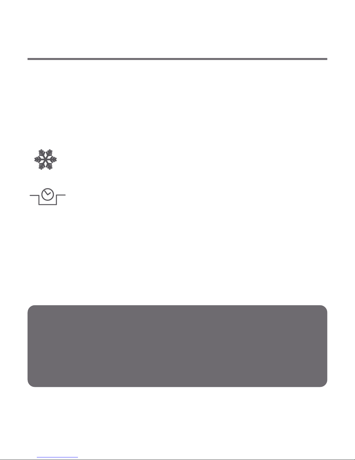
3 independent temperature settings
Day, night, anti-freeze.
9 independent temperature programs
Including 6-user defined ones.
Backlit LCD display
Backlit LCD display to control the device in areas with
poor lighting.
LCD
Thank you for purchasing the latest temperature controller based
on an advanced microprocessor.
3
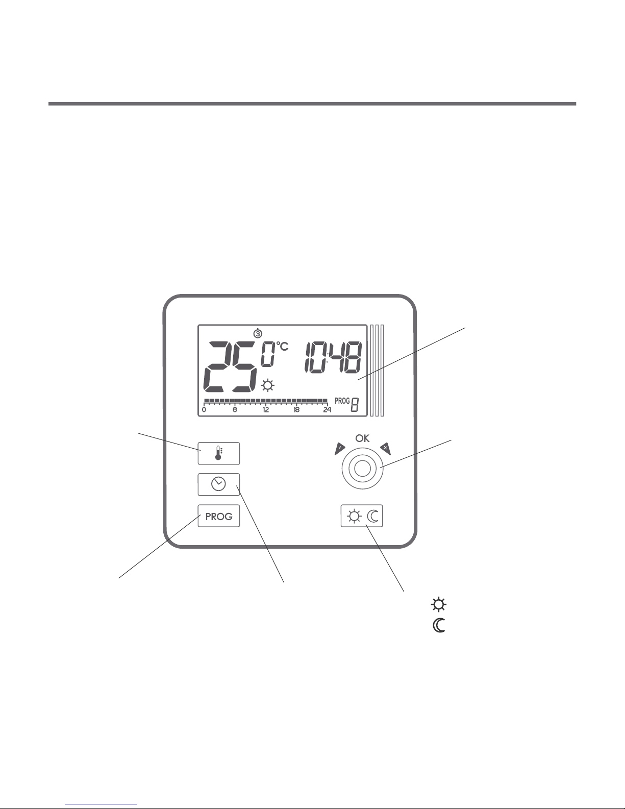
Temperature controller explained
LCD display
temperature
setting key
On the front of the enclosure, there are four function keys, backlit
LCD display and temperature control knob with the OK button.
date/time/day of
week setting key
mode select key:
selection key
day mode
night mode
setting knob with
integrated OK
button

4
1
2 3
4
13
5 6
7
8 9
11 1210
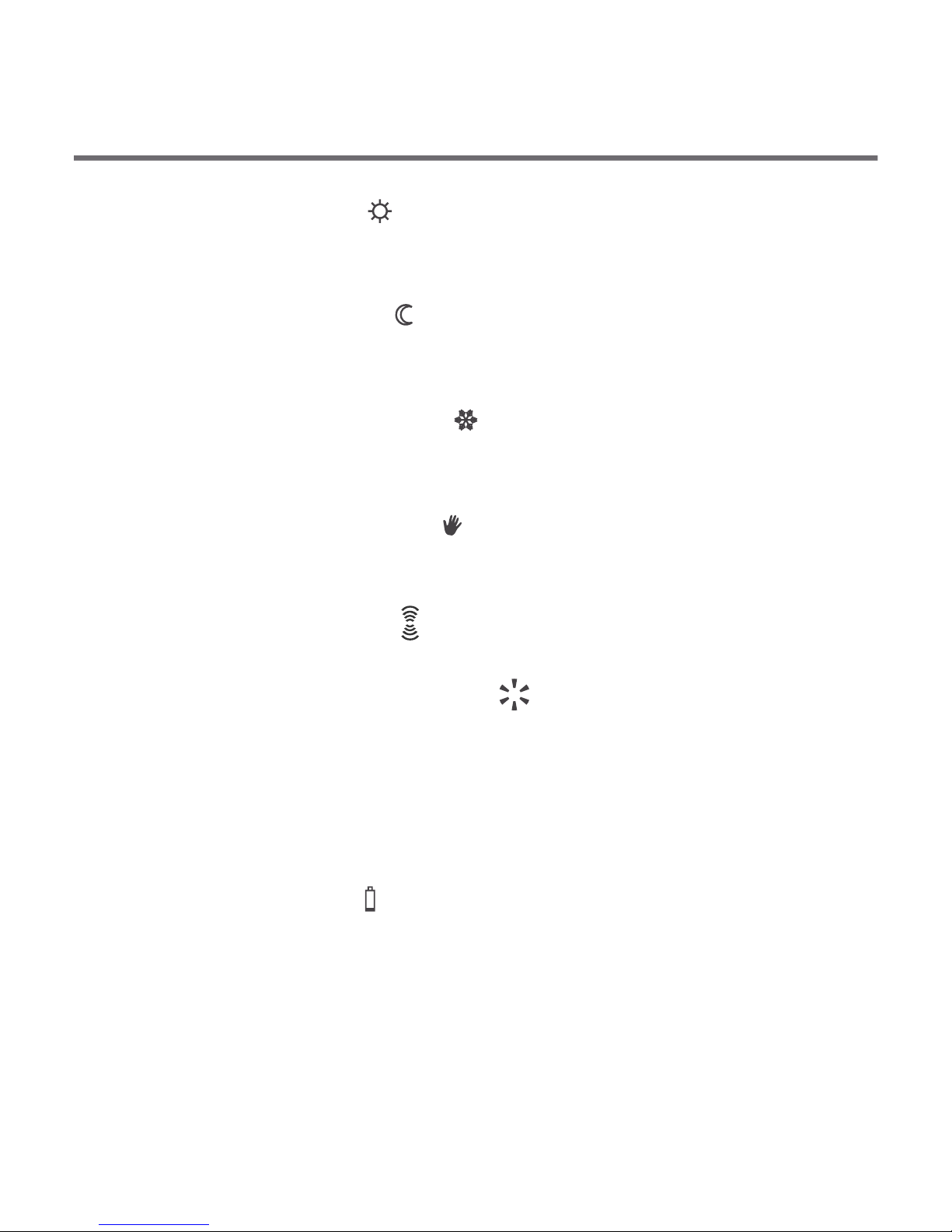
Display
1. Day of week ( ) Indicates the current day of the week.
Each day has a number assigned.
2. – In normal operating mode, the controller displays
the temperature of the room it is installed in.
3. Temperature unit – Indicates temperature displayed in
centigrade ( ).
4. Clock – Time displayed in 24-hour mode.
5. Timeline – Program progress indicator. Line divided to 24
sections, each corresponding to one hour. Indicates program
execution method. (see: "Timeline")
–
Temperature
5
6. Day mode indicator ( )
Indicates that the controller is in the day mode.
(see: "Temperature programming")
7. Night mode indicator ( )
Indicates that the controller is in the night mode.
(see: "Temperature programming")
8. Anti-freeze mode indicator ( )
Indicates that the controller is in the anti-freeze mode.
(see: "Anti-freeze mode”)
9 . Manual control indicator ( )
Appears if the programmed mode is switched off.
(see: "Manual control mode”)
11. Controller power on indicator ( )
Indicates the operating status. Visible when the controlled device
is started.
12. Program number
Indicates the number of program currently executed.
(see: "Factory programs" and "Weekly programming")
13. Battery exhausted ( )
Displayed when the battery voltage drops below the allowed
limit. Replace the battery as soon as possible.
NOTE: To save the parameters programmed, the battery
exchange operation should not last longer than 30 seconds.
10. ( ) – AURATON 3021R onlyTransmission symbol
Indicates ongoing communication with the RTH receiver.
6
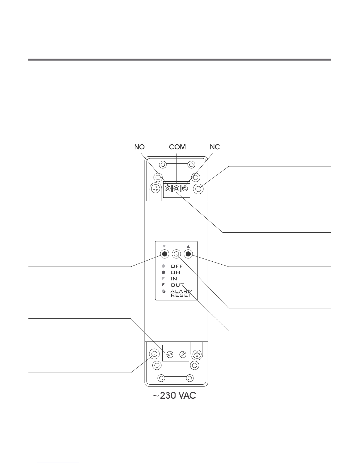
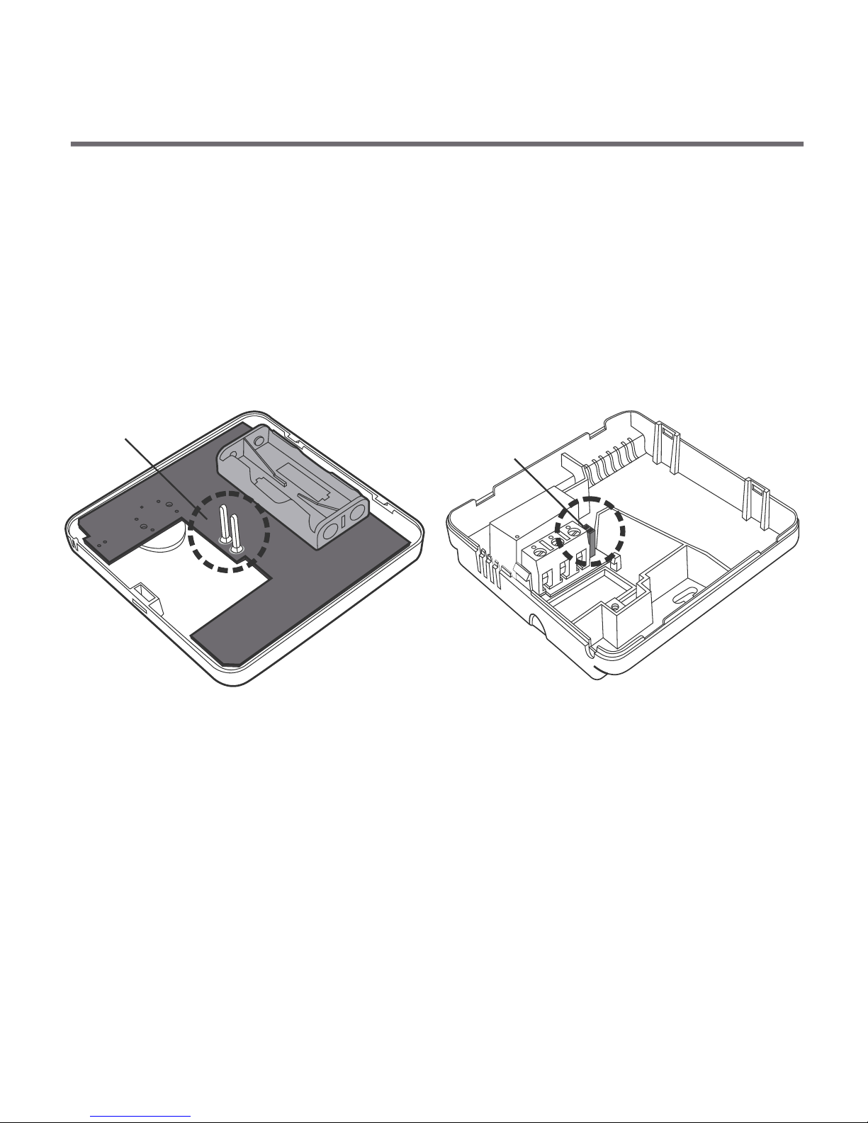
Description of the RTH receiver (AURATON 3021 RTH)
The AURATON RTH receiver cooperates with the AURATON 3021R
wireless receiver. The receiver is installed on the heating or air
conditioning device and can operate under the load of 16 A.
cable tie clamp
control connection terminal
(a terminal for fastening a two-core
cable of the heating or air conditioning
device to be controlled
button for deregistering
already paired devices
button for pairing devices
with the RTH receiver
LED indicating operation
of the device
cable tie clamp
power supply terminal
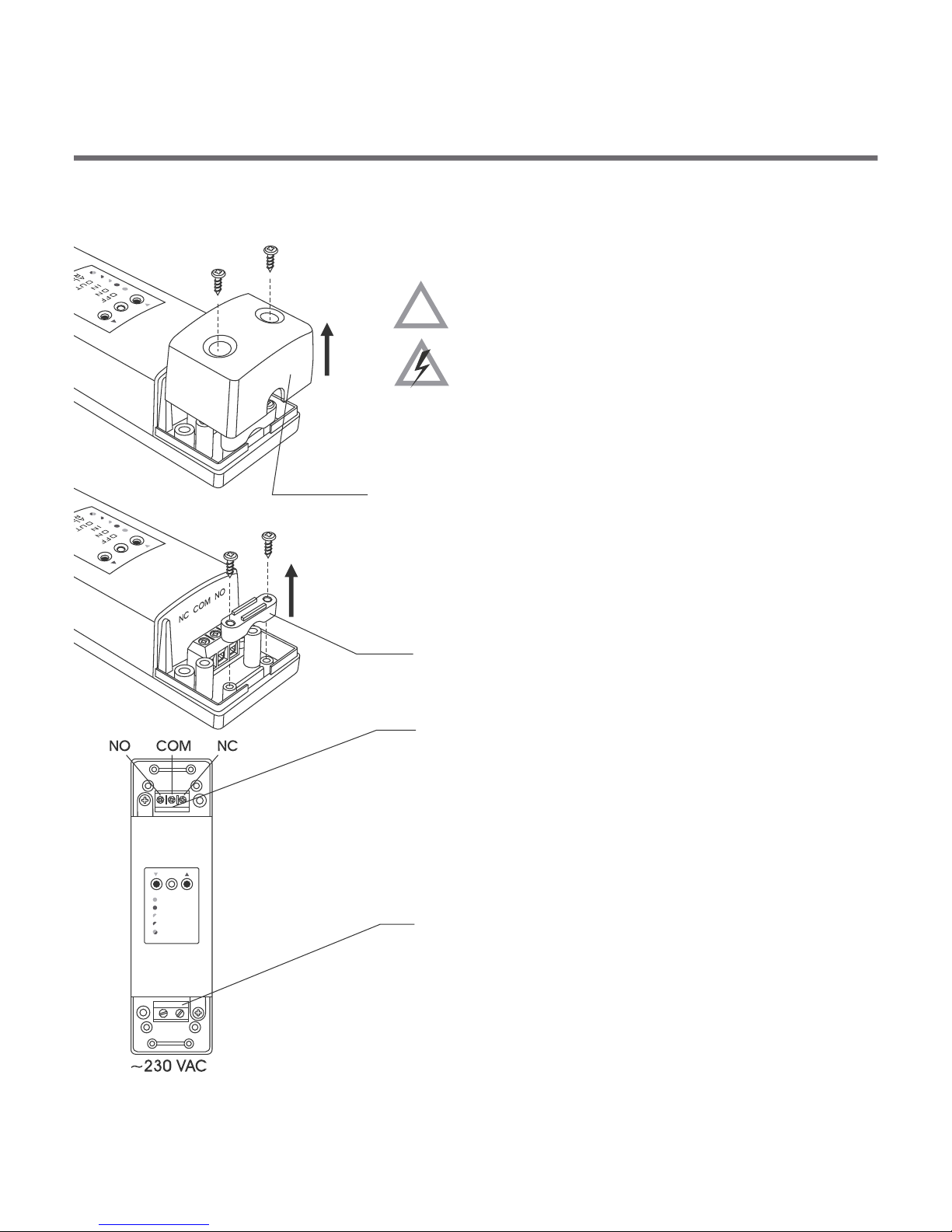
~230 VAC
legend
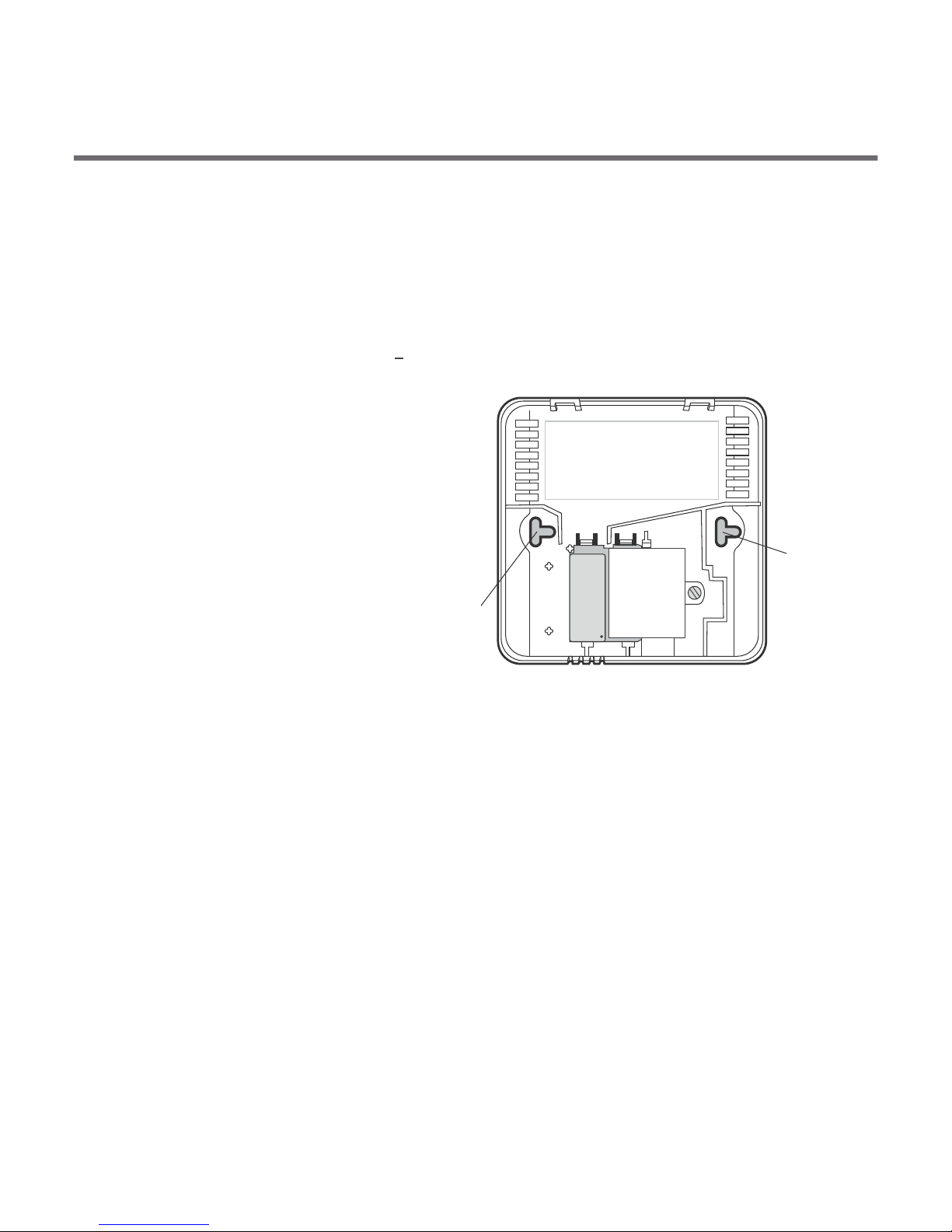
hole for fastening the receiver
to the wall with a screw
hole for fastening the receiver
to the wall with a screw
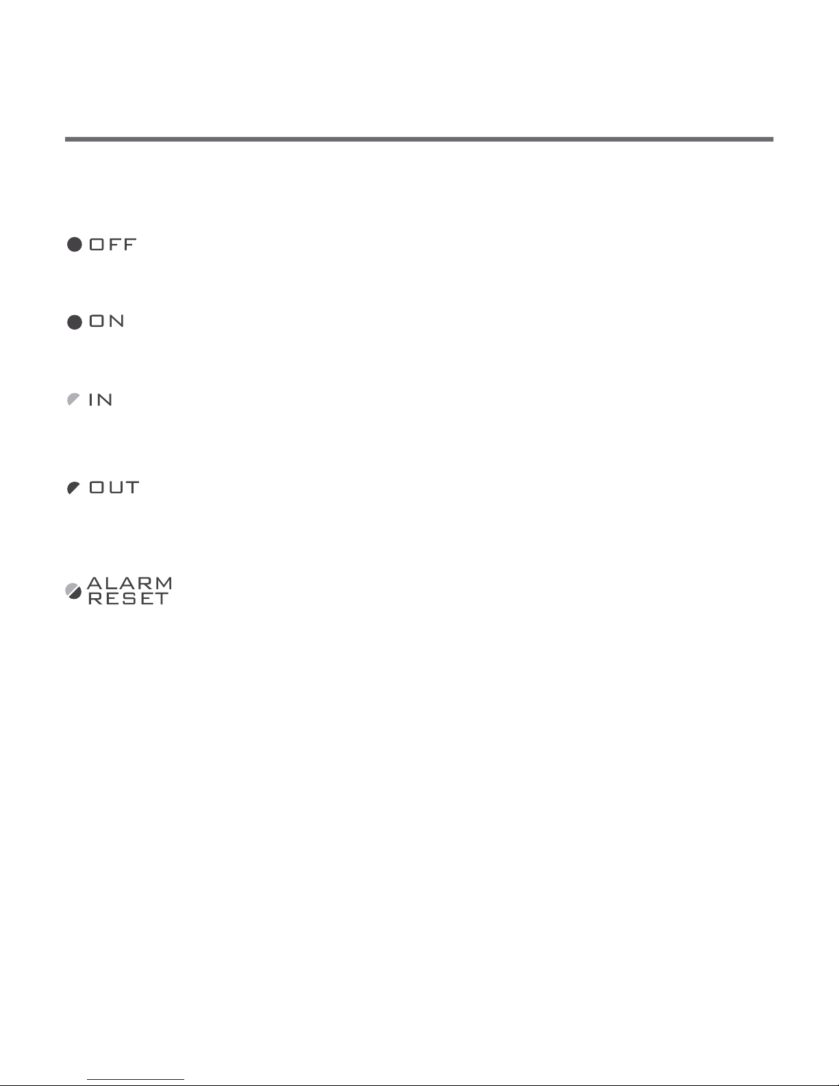
7
The LED light’s green – the output device is off (the contacts
COM and NC are closed).
The LED light’s red – the output device is on (the contacts
COM and NO are closed).
The LED flashes green – the RTH receiver awaits the device
to be paired (chapter: “Pairing the wireless regulator and the
RTH receiver”).
The LED flashes red – the RTH receiver awaits the device
to be deregistered (chapter: “Deregistering the regulator
from the receiver”).
The LED flashes alternating red and green:
ALARM - the RTH receiver has lost connection with one of
the paired devices (chapter “Special situations”).
RESET - receiver deregisters all previously paired devices -
(chapter “Deregistering all devices paired with the
RTH receiver”).
Legend - description of LED signalling
8 9
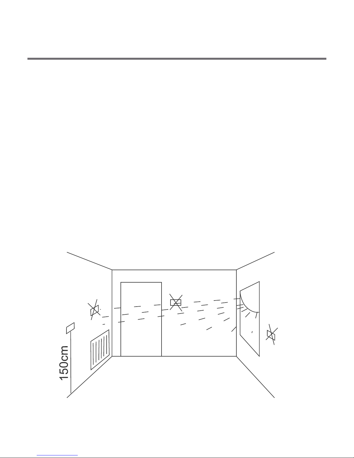
Selecting proper location for temperature
controller
Controller location largely affects its proper operation. When located
in a place without air circulation or exposed to direct sunlight, the
controller may not control the temperature properly. The controller
should be located on an internal wall of a building (partition wall) in
a place with free air circulation. Avoid locations near sources of heat
(TV set, heater, refrigerator) or places exposed to direct sunlight.
Location near doors and the resultant vibration may cause the
controller to function improperly.

1.
2.
1.
2.
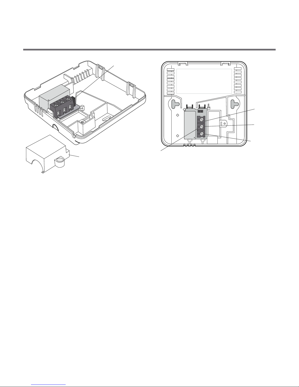
Wiring your AURATON 3021
To connect the wiring, remove the enclosure as described below:
Wiring terminals are located in the controller back wall, under
the plastic cover.
cover
screw
1. 2.
10 11
3.
NO COM
NC
NC
COM
NO
wire
terminals
cover
wire
terminals
It is a typical bistable relay. The NC terminal is not used in most cases.
NOTE: Replace the plastic cover after wiring.
Battery installation / replacement
The battery socket is located inside the controller, at the front of the
enclosure. To install the batteries, remove the controller enclosure
as described in the "Wiring your AURATON 3021" section.
NOTE: We recommend using alkaline bateries to supply AURATON
controllers. Rechargeable batteries should not be used because
their rated voltage is too low.

AURATON 3021
AURATON 3021 R
2x AAA 1,5 V
battery socket
Place two AAA 1.5V batteries in the battery socket
observing the correct polarity. ON 3021" section.
2x AAA 1,5 V
battery socket
A terminal block
An external
temperature sensor
AURATON 3021 DS / 3021 P
Connecting an external
temperature sensor.
12
CAUTION
Replacing the enclosure 3021
While replacing the front part of the enclosure on the back one, pay
attention to the pin connector that controls the relay.
While reassembling ensure that the pins engage with the pin
connector socket.
Pins
Pin
connector
socket
FRONT
ENCLOSURE
BACK
COVER
13
To fix the AURATON 3021 controller to the wall:
1. Remove the enclosure (as described in the "Wiring your
AURATON 3021" section).
2. Drill 2 holes diameter 6 mm
in the wall (use the back of
the controller enclosure to set
the right spacing of the
holes).
Fixing the controller to the wall
NO COM
NC
hole for a mounting
screw
hole for
a mounting
screw
3. Place plastic plugs in the drilled holes.
4. Screw the back of the controller enclosure to the wall with the
two screws provided.
5. Replace the controller enclosure.
NOTE: No expansion bolts are needed for wooden walls. Just drill holes
diameter 2.7 mm (instead of 6 mm) and screw the screws directly into
the wood.
14
OFF
ON
IN
OUT
ALARM
RESET
Fastening the RTH receiver
cover
NOTE !
When installing the receiver its power
supply must be disconnected. It is
recommended that the installation is
performed by a qualified specialist.
The permanent electrical system of
a building must include a breaker and
an overcurrent protection.
!
1. Take off protective covers from the lower
and upper part of the receiver.
2. Take off cable tie clamps from the lower and
upper part of the receiver.
3. Connect the heating device to the control
connection terminals of the receiver.
Proceed in accordance with the service
manual of the heating device. Most
commonly, the COM (common) and NO
(normally open) terminals.
4. Connect power supply conductors to the
power supply terminals of the receiver,
observing safety rules.
 Loading...