

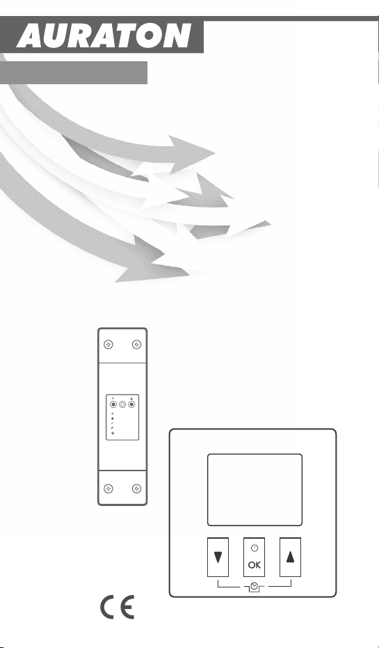
AURATON 200 RTH Instruction Manual
www.auraton.pl
AURATON RTH
OFF
ON
IN
OUT
ALARM
RESET
200 RTH
AURATON 200 RTH
Instruction Manual
dla oprogramowania w ver. F03 oraz F0A

2
3
Thank you for purchasing the modern temperature controller based on an
advanced microprocessor.
AURATON 200 RTH
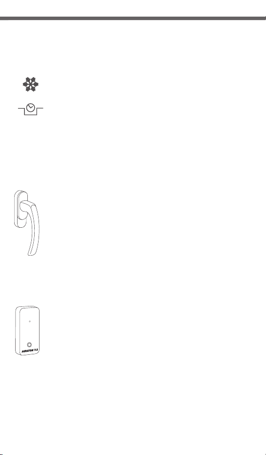
FrostGuard function:
Protects the interior from freezing
Enables cyclic reduction of set temperature
by 3°C for 6 hours.
Backlit LCD display
LCD
The backlit display enables device control even in dark rooms.
Optional elements of the system
AURATON H-1
Window handle (sold separately)
A window handle, equipped with a position sensor and
a transmitter, is an optional element of the system. This way the
handle provides information about the state of the window.
The handle also differentiates between 4 widow positions:
opened, closed, pivoted and trickle ventilated (microventilation). The handle transmits information to the RTH
receiver that controls the relay, e.g. switching off a heater in the
event of opening the window or lowering the temperature down
to 3 °C to conserve energy. One RTH receiver operates with max
25 handles.
AURATON T-2
Thermometer (sold separately)
An optional element of the system allowing for controlling
temperature in a room other than that with the AURATON 200
RTH regulator.
4
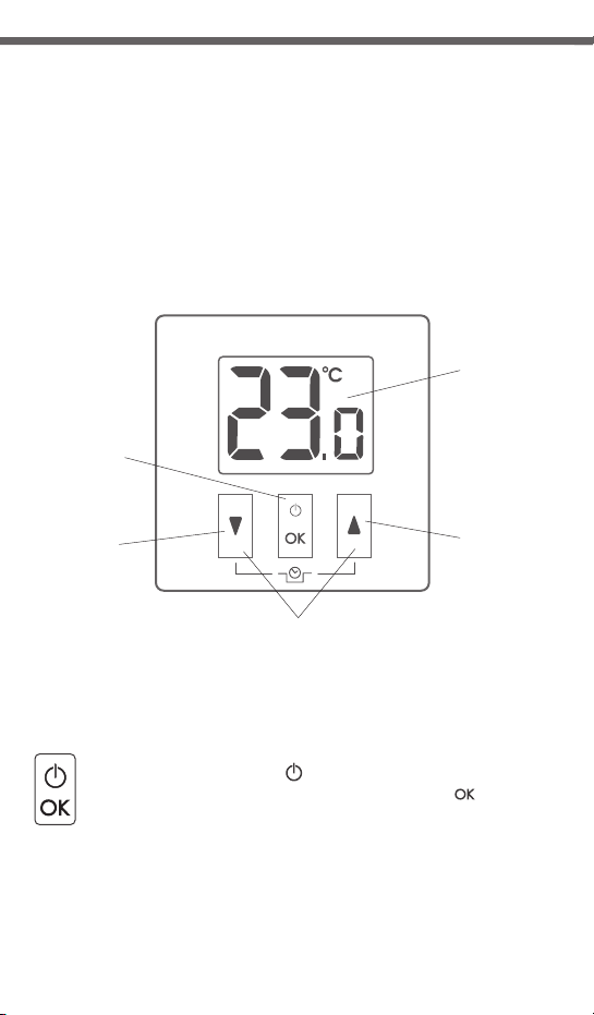
AURATON 200 RTH temperature
controller explained
The front of the enclosure has a backlit LCD display and three function
buttons.
AURATON 200
acknowledge
or on/off key
temperature
decrease key
temporary temperature decrease
ź hold – controller on/off ( )
ź short press – acknowledge temperature setting ( )
mode keys
LCD display
temperature
increase key
5
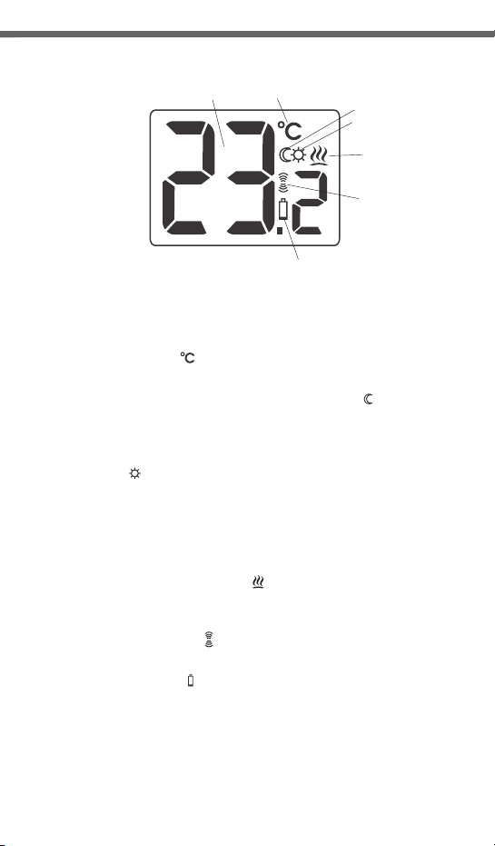
Display screen
1
2
3
4
5
6
7
1. Temperature
In n o rma l op era tin g mo de, t h e co ntro l ler d i spl ays
the temperature of the room it is installed in.
2. Temperature unit ( )
Indicates temperature displayed in centigrade.
3. Temporary temperature decrease mode indicator ( )
Appears when the temporary temperature decrease program
is active.
4. Tempo rary tem perat ure de crease mod e programming
indicator ( )
WIndicates the temporary temperature decrease mode planned
by the user. Displayed when the mode is not executed but the
function of the temporary temperature decrease is active
(refer to "Temporary temperature decrease setting" section for
more details).
5. Controller power on indicator ( )
Indicates the operating status. Appears when the controller
device is started.
6. Transmission symbol ( )
Indicates communication with the receiver.
7. Battery exhausted ( )
Displayed when the battery voltage drops below the allowed
limit. Replace the battery as soon as possible.
6 7
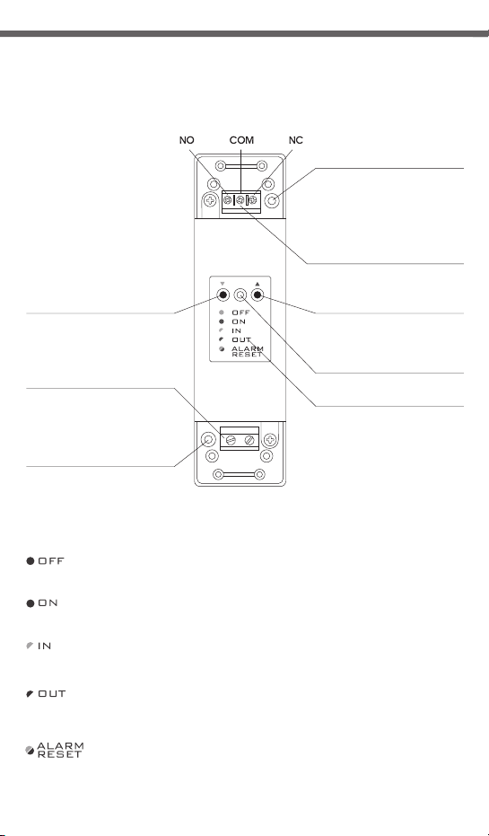
Description of the AURATON RTH receiver
The AURATON RTH receiver cooperates with the AURATON 200 RTH wireless
receiver. The receiver is installed on the heating or air conditioning device and can
operate under the load of 16 A.
hole for fastening the receiver
to the wall with a screw
control connection terminal
(a terminal for fastening a two-core
button for pairing devices
with the RTH receiver
cable tie clamp
power supply terminal
~230V AC
hole for fastening the receiver
to the wall with a screw
cable of the heating or air conditioning
AURATON RTH
device to be controlled
button for deregistering
already paired devices
LED indicating operation
~230V AC
Legend - description of LED signalling
The LED light’s green – the output device is off (the contacts COM
and NC are closed).
The LED light’s red – the output device is on (the contacts COM and
NO are closed).
The LED flashes green – the RTH receiver awaits the device
to be paired (chapter: “Pairing the AURATON 200 RTH wireless
regulator and the RTH receiver”).
The LED flashes red – the RTH receiver awaits the device
to be deregistered (chapter: “Deregistering the regulator from the
RTH receiver”).
The LED flashes alternating red and green:
ALARM - the RTH receiver has lost connection with one of the paired
devices (chapter “Special situations”).
RESET - receiver deregisters all previously paired devices - (chapter
“Deregistering all devices paired with the RTH receiver”).
cable tie clamp
of the device
legend
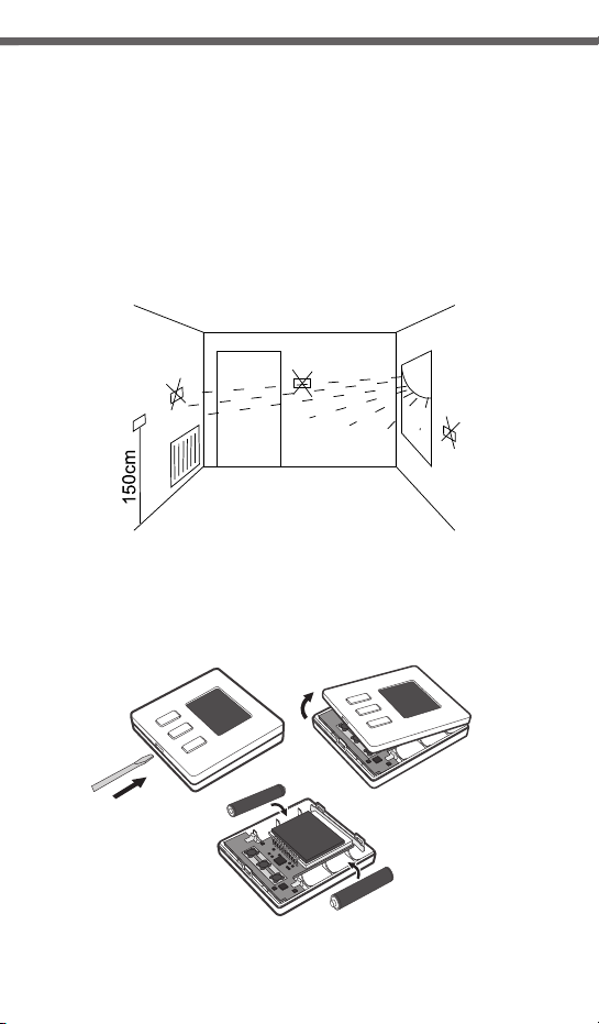
Selecting proper location for AURATON 200 RTH
temperature controller
Controller location largely affects its proper operation. When located in a
place without air circulation or exposed to direct sunlight, the controller may
not control the temperature properly. The controller should be located on an
internal wall of a building (partition wall) in a place with free air circulation.
Avoid locations near sources of heat (TV set, heater, refrigerator) or places
exposed to direct sunlight. Location near doors and the resultant vibration
may cause the controller to function improperly.
Battery installation / replacemen in AURATON 200 RTH
Battery sockets are located inside the controller on both sides of the display.
To install the batteries, remove the controller enclosure as shown in the
figure.
Place two AAA 1.5 V batteries in the battery socket observing
the correct polarity.
8 9
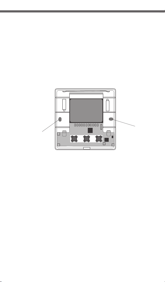
Fixing the AURATON 200 RTH controller to the wall
To fix the AURATON 200 controller to the wall:
1. R em ov e t h e e nc lo su r e (a s d e sc ri be d o n t he " Ba tt er y
installation/replacement" section).
2. Drill 2 holes diameter 6 mm in the wall (use the back of the controller
enclosure to set the right spacing of the holes).
hole for a
hole for a
mounting screw
3. Place plastic plugs in the drilled holes.
4. Screw the back of the controller enclosure to the wall with the two screws
provided.
5. Install the batteries and replace the controller enclosure.
NOTE: No expansion bolts are needed for wooden walls. Just drill holes diameter 2.7 mm
(instead of 6 mm) and screw the screws directly into the wood.
mounting screw
Alternative fixing methods
Th e cont rol ler c an be m ount ed to a s moo th surf a c e with
e.g. two-sided adhesive tape.
The controller can also be placed in any location on an even surface on
a support at the back of the enclosure.
 Loading...