

AURATON 1107 User Manual
1107
www.a urato n.pl
20 80
50
EN
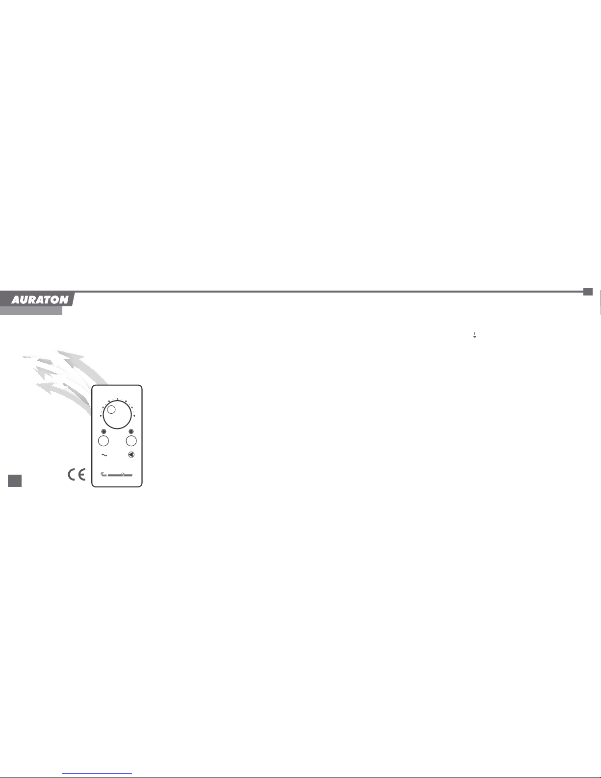
Hot Domestic Water (HDW) pump controller
AURATON 1107
Congratulations on your purchase of the AURATON 1107
controller. Our device will save you energy and ensure
thermal comfort for many years.
Before you start using the controller, please read this
instruction carefully.
1. APPLICATION
AURATON 1107 is intended for automatically switching on
and off circulation pumps depending on the temperature.
In hot domestic water (HDW) systems, the controller-pump
assembly forces circulation of water in HDW systems with
coal-fired and gas-fired boilers without systems controlling
the operation of the pump. The controller’s sensor
measures the water temperature in the HDW tank.
In HDW systems, th e controller maintains constant
temperature of water in the tank or in the HDW circuit.
The range of settings for the HDW pumps is from 20°C to
80°C. The hysteresis (difference between the temperature
at which the device is switched on and off) is equal to 4°C.
2. INSTALLATION
2.1. Mounting the controller.
ź
support using two screws (the concrete anchors with
screws are delivered with the controller).
ź The cables extending from the controller must be fixed
to the wall.
2.2. Mounting the sensor.
ź Install the sensor in the HDW tank.
NOTE: The sensor must not be immersed in liquids
or installed at flue gas outlets to the stack.
The controller must be mounted on a wall or another
EN
AURATON 1107
User Manual
The GUARD system installed in the AURATON 1107
controller prevents seizure of the rotor of unused pump.
If the pump is not used for a long time, the built-in
processor starts the pump automatically for 30 seconds
every 14 days.
NOTE: In order for the system to work after a long period
of non-use, the AURATON 1107 controller must be
switched on at all times.
2.3. Connecting the power supply cable to the
pump.
ź Connect the yellow or yellow-green con ductor
(ground or protective neutral grounding) to the
( ) terminal .
ź Connect the blue wire to the ( N ) terminal.
ź Connect the brown wire to the ( L ) terminal.
2.4. Checking the connection.
ź Check if the wire is connected properly and fix the lid
of the terminal box to the pump’s motor with screws.
2.5. Connecting the controller.
ź After the wires are secured to prevent accidental
pulling, connect the power supply cable to a 230 V/50
Hz power outlet with a grounding pin. The ambient
temperature in the place where the controller
is installed must not exceed 40°C.
EN
EN
ź 3.3. Continuous operation.
ź Press the button marked as ( ) and then the ( )
button (the red diode and the green diode are lit).
ź The pump continues to work regardless of the
temperature preset on the controller and the actual
temperature in the location of the sensor.
Temperature control range 20 – 80°C
Hysteresis 4°C
(on/off temperature difference)
Power supply voltage 230V AC
Maximum load 6A
3. OPERATION OF THE CONTROLLER
3.1. Switching the controller on
ź
ź The red diode will lit up.
3.2. Automatic operation.
ź If the green diode is not lid, the controller switches the
pump on/off depending on the temperature set on the
controller's knob.
ź The pump is switched on (green diode blinks) when the
setting temperature is maintained. The controller
switches the HDW pump off if the temperature
mea sured by th e sens or exc eeds the pr eset
temperature value by 2°C and switches the pump on
if the temperature drops below the preset value by 2°C.
NOTE:
If the temperature measured by the sensor exceeds
90°C, the HDW pump is switched off. This prevents
excessive heating of the water in the tank.
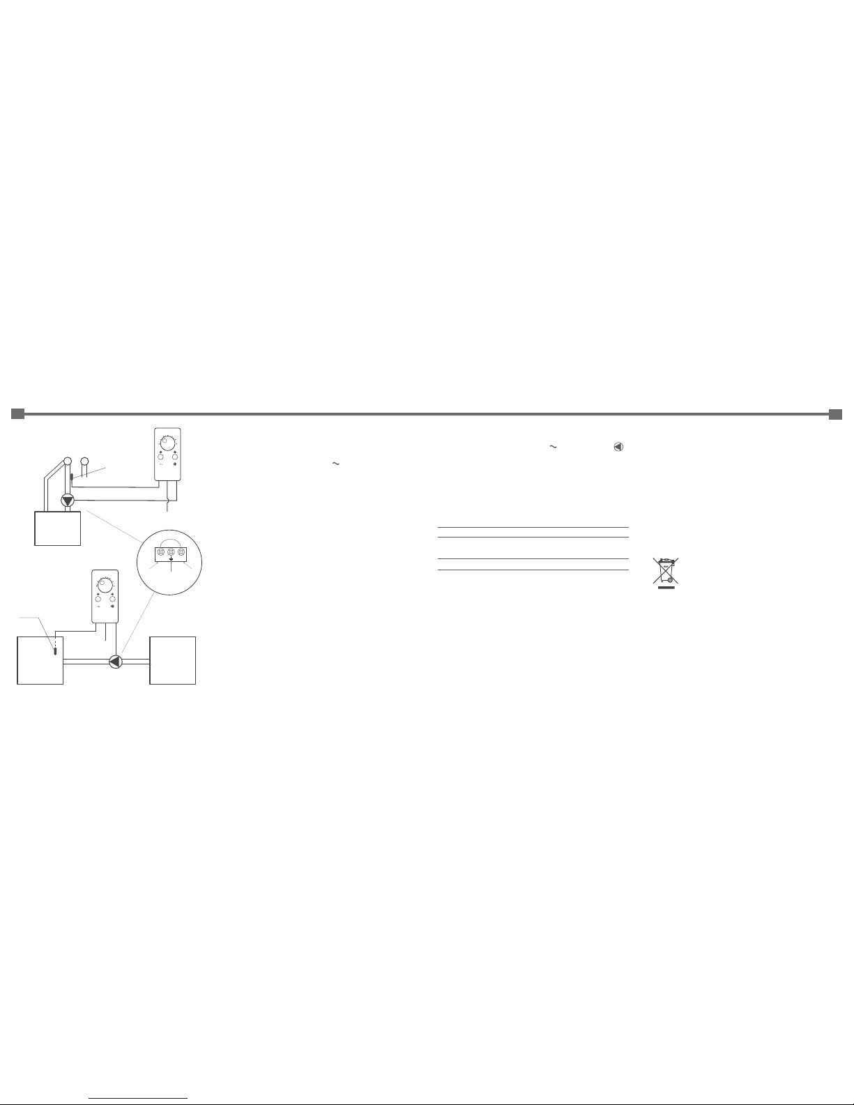
Press the button marked as ( ).
gas
boiler
pump
temperature
sensor
HDW
tank
230V
20 80
50
Wiring diagram
with a HDW tank
L N
brown yelow
green
blue
HDW
tank
pump
230V
temperature sensor
(fix with a band)
HW CW
20 80
50
Wiring diagram of a HDW circuit
4. TECHNICAL DATA
Cleaning and maintenance
ź The outside of the controller must be cleaned with
a clean cloth. Do not use solvents (such as benzene,
thinners, or alcohol).
ź Do not touch the device with wet hands. This can lead
to electric shock or serious damage to the device.
ź No not expose the device to excessive impact of smoke
or dust.
ź Avoid contact of the device with liquids and moisture.
Disposal of the device
The device is marked with a symbol of a crossed
waste bin. Pursuant to European Directive
2002/96/EC and to the Act on waste electrical
and electronic equipment, such mark indicates
that the device, at the end of its service life,
must not be disposed off together with other household
waste.
The user is required to deliver it to a waste electrical and
electronic equipment collection point.
 Loading...