

Page 1
www.speedfitUFH.co.uk
For models:
JGSTATW2W
JGSTATW2B
JGSTATW1W
JGSTATW1B
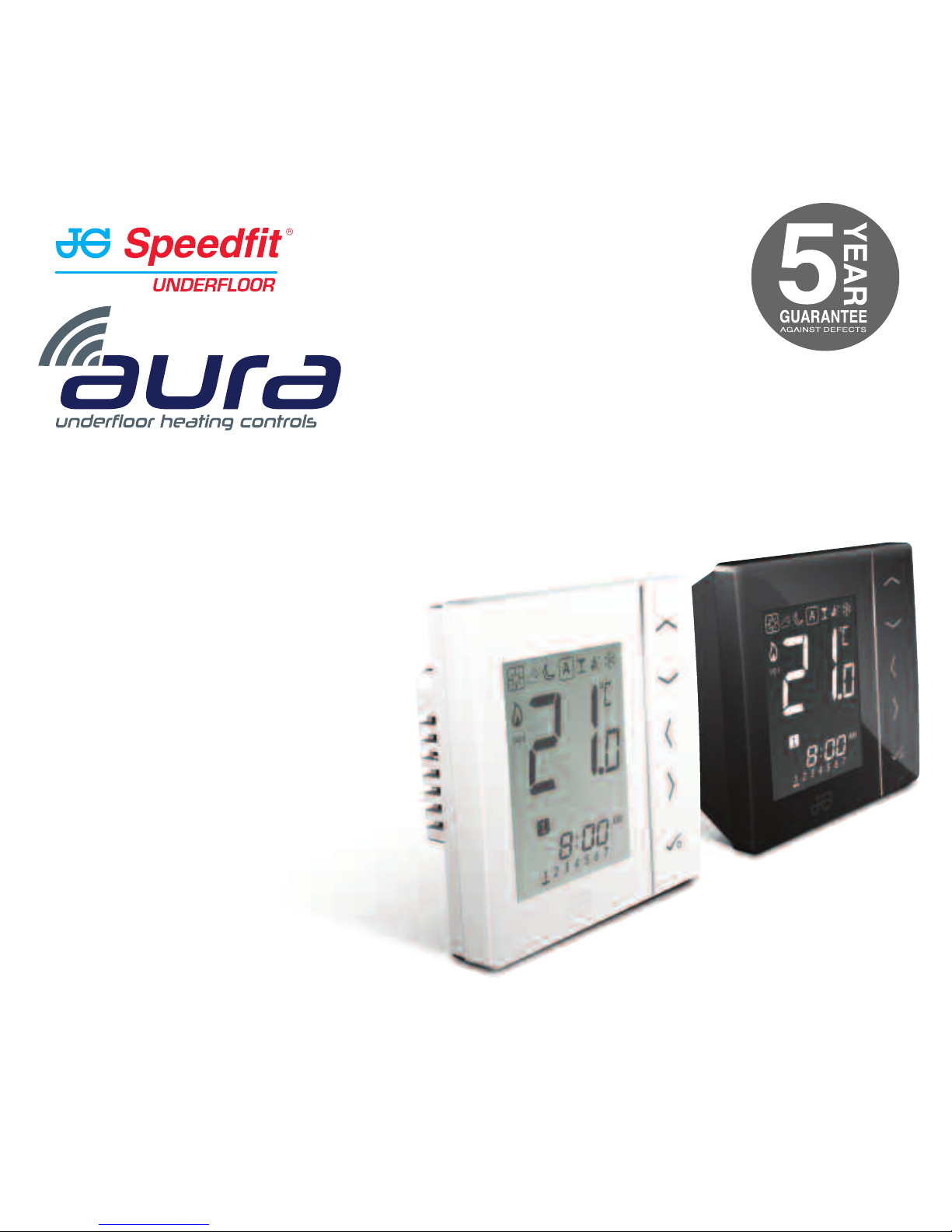
Instruction Manual
Wireless Thermostats
230v and Battery Operated
Page 2
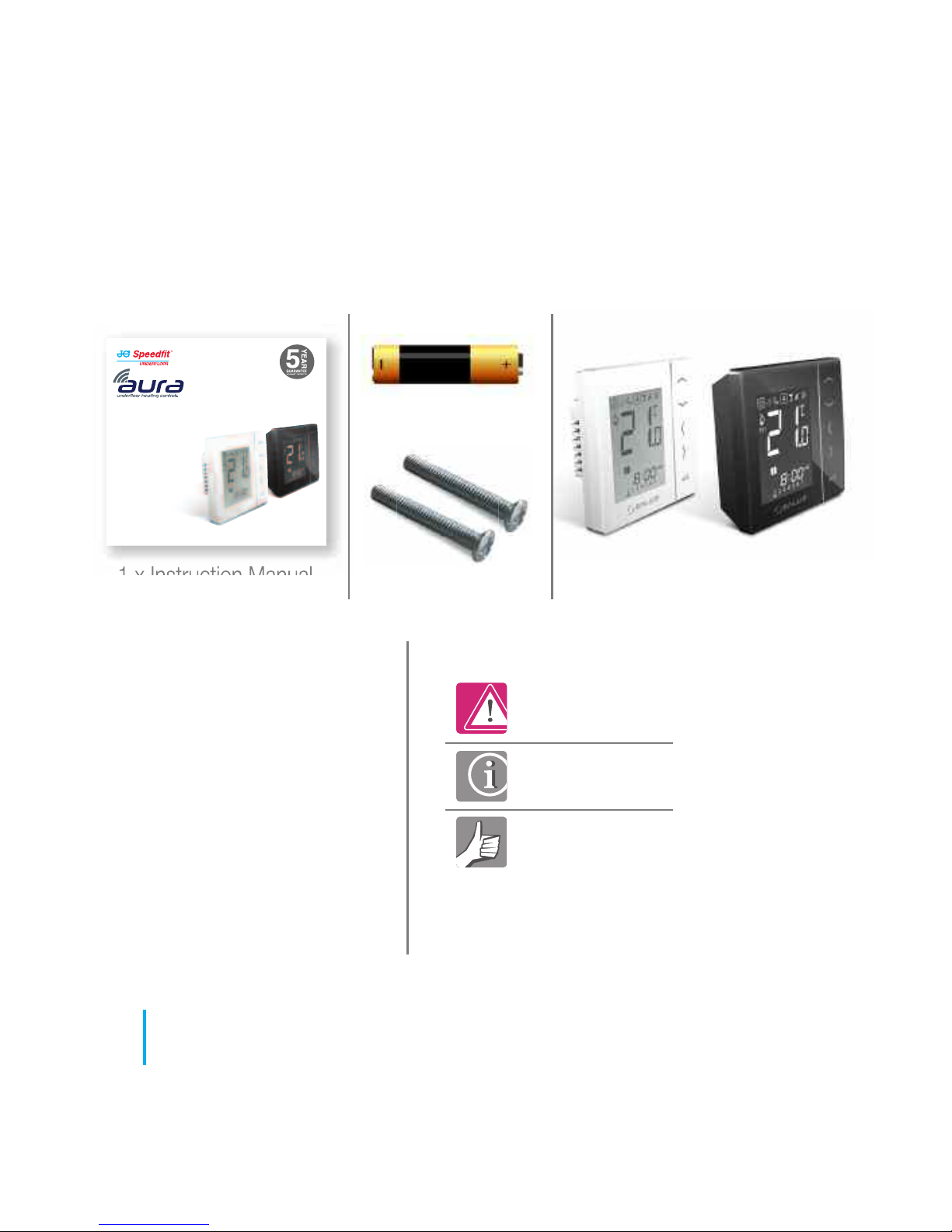
1 x Instruction Manual JGSTATW2
4x AAA Batteries
JGSTATW1
www.speedfitUFH.co.uk
For models:
JGSTATW2W
JGSTATW2B
JGSTATW1W
JGSTATW1B
Instruction Manual
Wireless Thermostats
230v and Battery Operated
Fixing screws
Box contents:
02
JGSTATW Instruction Manual
Contents
Instruction manual:
• Box contents
• Introduction
• Product Compliance
• System options overview
• Installation
• Parameter settings
• Error codes
• User guide
• Installers notes
Icons used in this manual:
Safety
Important info
Your benefit
For latest PDF instruction manual
please go to www.speedfitUFH.co.uk
Page 3
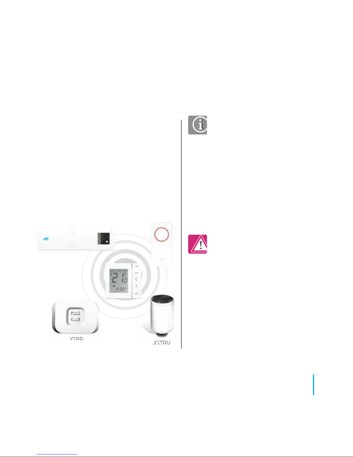
Introduction. Thank you for purchasing
one of our Speedfit Aura Wireless
Thermostat models. It must be used with
the JGCO Wireless Coordinator. The
Wireless Coordinator allows
communication with other devices in the
Aura Wireless system range including
wiring centre, system receiver and TRV.
Product Compliance. This
product is CE compliant and
meets the following EC
Directives:
RoHS2 2011/65/EU, ElectroMagnetic Compatibility
directive 2004/108/EC and
Low voltage directive
2006/95/EC.
Safety Information. Use in
accordance with the
regulations. The Aura JGSTAT2
is to be used for room control
of heating and hot water
systems inside buildings.
JGWCW
JGBR
JGTRV
JGSTATW
JGCO
03
www.speedfitUFH.co.uk
Product Compliance & Safety Information
We hope you enjoy
this product...
Page 4
04
JGSTATW Instruction Manual
Product Compliance & Safety Information
Emergency. Switch off the
voltage to the individual
thermostat, wiring centre or
complete system.
Sources of danger. The
thermostat must be disconnected
from mains supply before
removing the cover.
For the installer. Please enter
any parameter changes in the
Installer Notes section (pages
90 and 91).
Installer parameter settings.
Aura Wireless Thermostats are
equipped with an Installer
Parameter section (see page 40).
This must only be entered by the
installer or a competent person.
Changing these parameters can
have a serious effect on your
heating system.
230V AC
Warning. This product must be
fitted by a competent person.
Installation must comply with the
guidance, standards and
regulations applicable to the
location where the product is
installed. Failure to comply with the
requirements of the relevant
guidance, standards and
regulations could lead to
prosecution, injury or death.
These instructions are applicable to the
Aura models stated on the front cover of
this Instruction Manual only.
Warning. Always isolate the
AC Mains supply before
installing or working on any
components that require 230v
AC 50Hz supply.
Page 5
Programmable Room
Thermostat (PRT)
*
Grouping and timer option only available
when used with wiring centre.
UFH Manifold
Wiring Centre
Radiator
Boiler
Hot Water
TRV
Towel Rails
05
www.speedfitUFH.co.uk
System Overview - Configuration Options
Group Control
Thermostat
*
Group
Thermostat
*
Timer
1
2
3
4
The unit can be
configured to either
one of the following
SYSTEM OVERVIEW
Page 6

Programmable Room Thermostat (PRT). When configured for PRT (see page 32) it
mainly works by itself and allows the user to have separate Time and Temperature control of
each zone on the wiring centre, radiator valve or system receiver. Features like Vacation, Party
and Frost mode have to set on each individual thermostat. All PRTs paired with a wiring centre
can also use the global heat/cool changeover function if the your system supports this. This
is achieved by using the heat/cool changeover connection on the wiring centre (see the Wiring
Centre Instruction Manual).
Group Control Thermostat. When configured as a Group Control Thermostat (see page
32) and paired to a wiring centre, the unit allows central control of up to 7 group thermostats
(see below). There can be a maximum of 2 groups per 8 zone wiring centre. Permanent
temperature override, Holiday, Party and Frost modes can be selected centrally from the
Group Control Thermostat. Holiday mode will also be applied to a timer if applicable.
Thermostats can also be globally changed from heating to cooling thermostats if your system
supports this by using the switched input connection on the JGWCW (see te Wiring Centre
Instruction Manual).
Group Thermostat. When configured as a Digital Thermostat with an assigned group (see
page 31), the unit will follow the time schedule and override modes of the Group Control
Thermostat. At least one Group Control Thermostat is required for grouping (see above). The
Group Thermostat can have its own programmed temperatures, manual override and also be
removed from the group temporarily or permanently.
Timer. When configured as a Timer (see page 32), the unit will operate without temperature
control. In this configuration, the unit can be used as a Hot Water Timer. The Timer will also
follow a Group Control Thermostat when Holiday mode has been activated.
06
JGSTATW Instruction Manual
System Overview - Configuration Options
Page 7
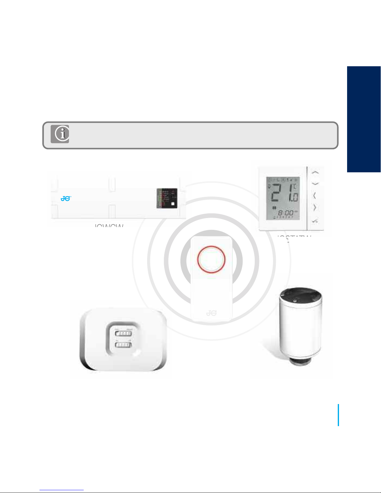
JGCO Wireless coordinator required for communication between these devices.
JGWCW
JGSTATW
JGTRV
JGBR
JGCO
07
www.speedfitUFH.co.uk
System Overview - Wireless Coordinator
SYSTEM OVERVIEW
Page 8
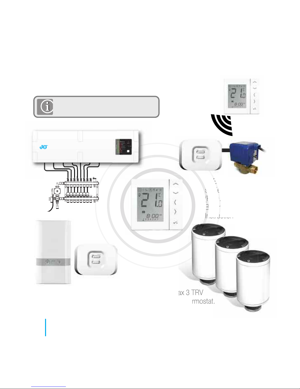
The thermostat can communicate
with all of these Aura devices.
JGBR configured to Boiler Receiver (RX1).
Refer to JGBR Instruction Manual.
JGBR configured to
single room receiver
(RX2). Refer to JGBR
Boiler Receiver
Instruction Manual.
Max 3 TRV
per thermostat.
UNDERFLOOR HEATING MANIFOLD
08
JGSTATW Instruction Manual
System Overview - Speedfit Aura
Page 9
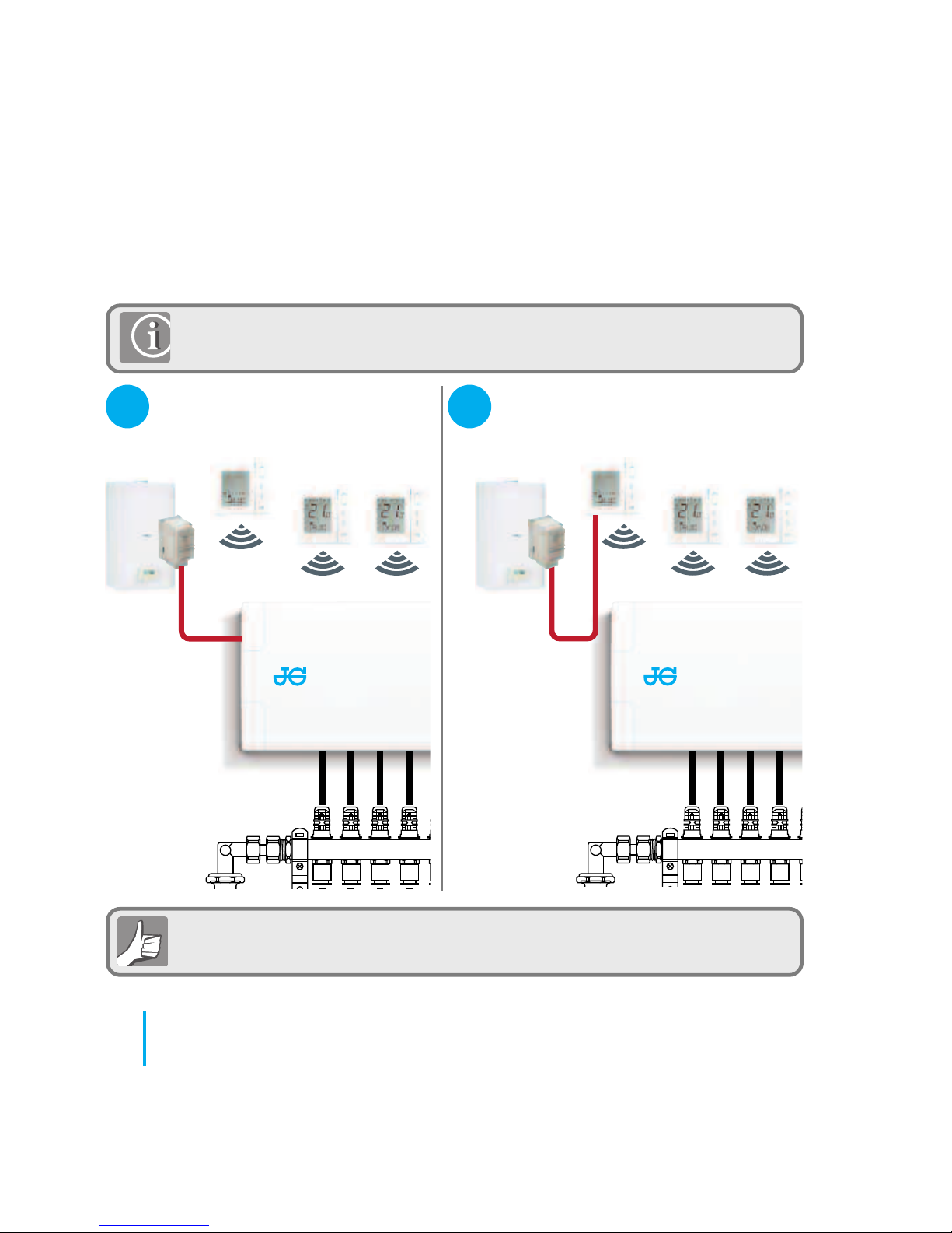
When the unit is configured as a hot water timer (see page 32) there
are two methods of connecting the cylinder thermostat.
09
www.speedfitUFH.co.uk
System Overview - Hot Water Option
Unit configured to
Hot Water Timer.
Cylinder thermostat options:
Connected directly to JGWCW (default).
Connected directly to Aura Wireless Thermostat
(requires additional parameter change. See page 57).
1
2
SYSTEM OVERVIEW
Page 10
10
JGSTATW Instruction Manual
System Overview - Hot Water Option
Please refer to the Wiring Centre Instruction Manual and pages 15 and 20
for more information.
Connected direct to JGWCW
(default).
1
For convenience there is a unique built in option allowing the cylinder
thermostat to be connected to either the HW Timer or Wiring Centre.
2
Connected direct to JGSTATW (requires
additional parameter change see page 57).
Page 11
Not
Do not insta
Only the te
Not
Do not insta
Only the te
Not
Do not insta
Only the te
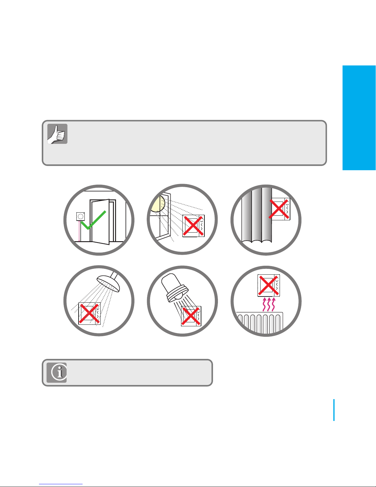
Mounting position and installation. To ensure trouble free operation and efficient
control, the unit is best positioned in a draft free area and at 130cm from the
floor. Do not position the thermostat near any heat source, behind curtains,
direct sunlight or an area of high humidity.
11
www.speedfitUFH.co.uk
Installation - Thermostat Mounting
Not to be positioned on an exterior wall.
INSTALLATION
130cm
Page 12
60mm
12
JGSTATW Instruction Manual
Installation - Thermostat Mounting (JGSTATW1)
1
2
3
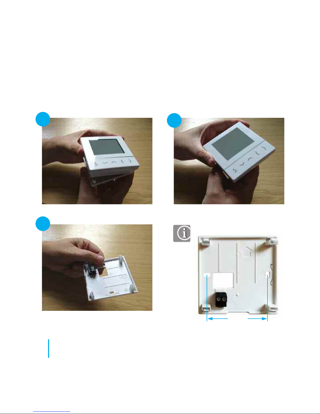
Carefully remove the front housing.
Page 13
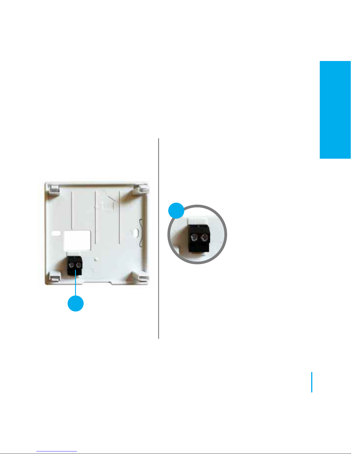
Understanding your terminal connections.
Sensor Terminals.
Can be used for an
external Air or Floor
sensor when configured
as thermostat. Can also
be used for Cylinder
thermostat when
configured for HW. See
page 57.
13
www.speedfitUFH.co.uk
Installation - Terminal Connections (JGSTATW1)
1
1
Rear of unit
INSTALLATION
Page 14
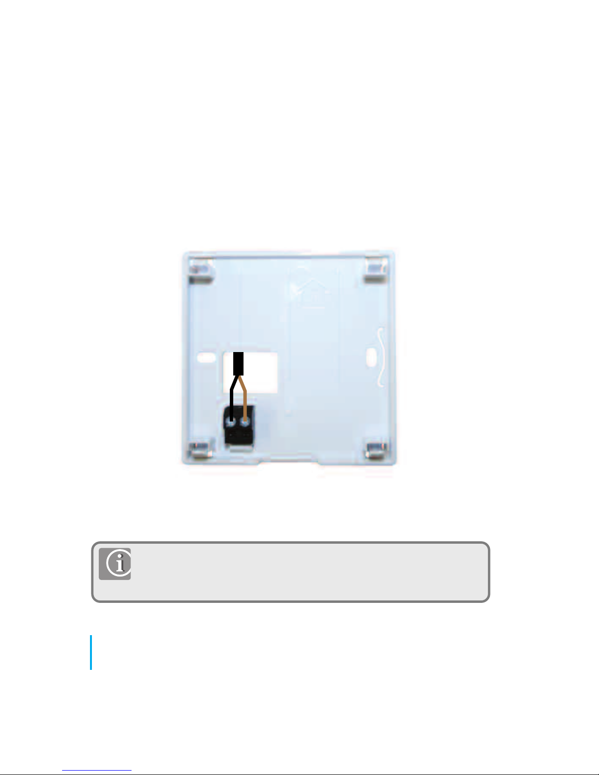
Note: If you are using an external sensor, the unit has to be
configured for External Air Sensor or Floor Protection Sensor please
see Device Parameter setting page 57.
Speedfit Aura External sensor (Sold separately).
14
JGSTATW Instruction Manual
Installation - Thermostat External Sensor (JGSTATW1)
Page 15
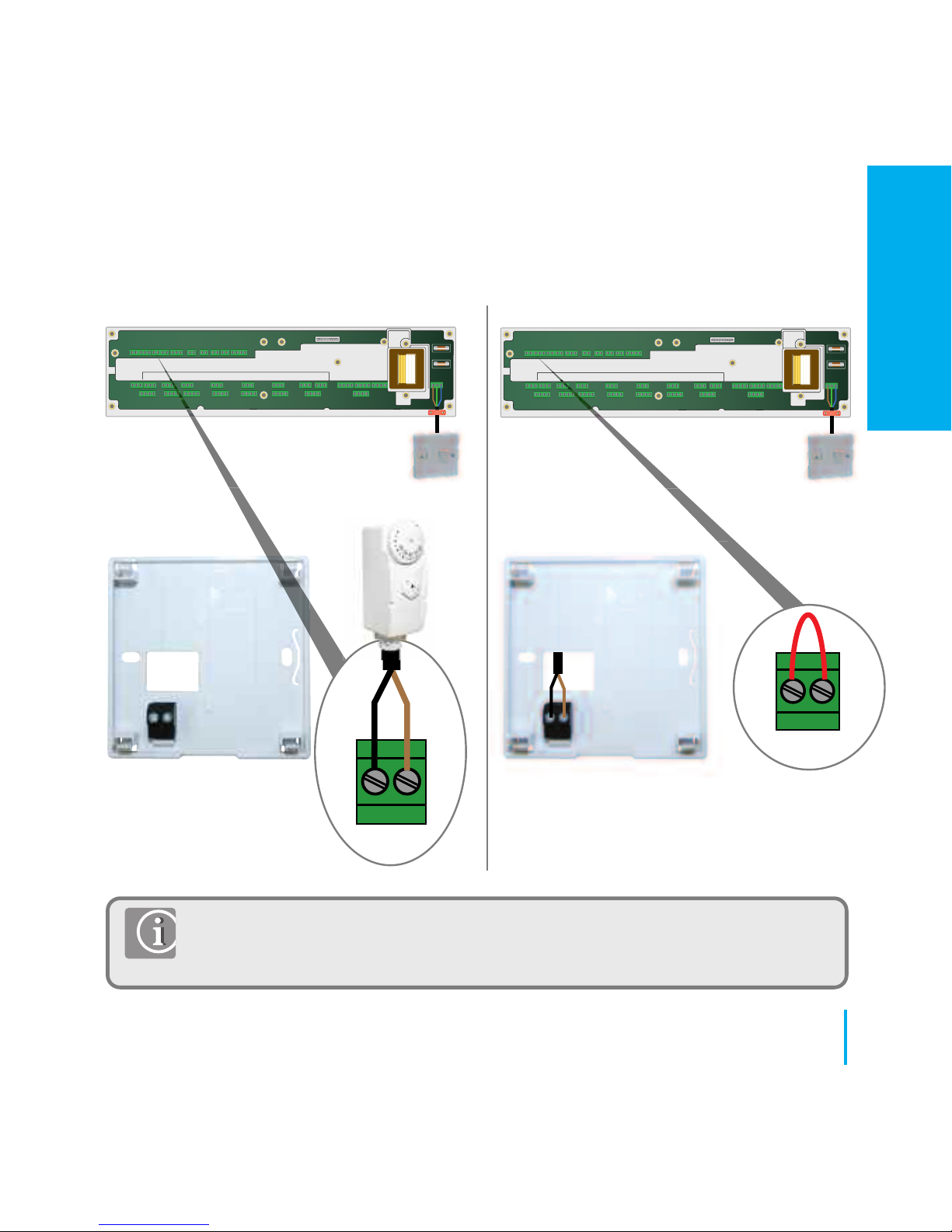
Note: Optional - The JGSTATW1 can be configured for connection to a cylinder
thermostat. Please see Device Parameters on page 57. For additional wiring
centre information refer to Wiring Centre Instruction Manual.
15
www.speedfitUFH.co.uk
Installation - Hot Water Cylinder Thermostat (JGSTATW1)
WC connected cylinder
thermostat (Default).
HW Timer connected to
cylinder thermostat.
Link must
be fitted
ZONE 1
SL N L SL N L SL N L SL N L SL N L SL N L SL N LSL N L
ZONE 2 ZONE 3 ZONE 4 ZONE 5
ZONE 6 ZONE 7
ZONE 8
5 x 20mm
5 x 20mm
IN OUT
Cylinder thermostat
ZONE 1
SL N L SL N L SL N L SL N L SL N L SL N L SL N LSL N L
ZONE 2 ZONE 3 ZONE 4 ZONE 5
ZONE 6 ZONE 7
ZONE 8
5 x 20mm
5 x 20mm
IN OUT
INSTALLATION
Page 16
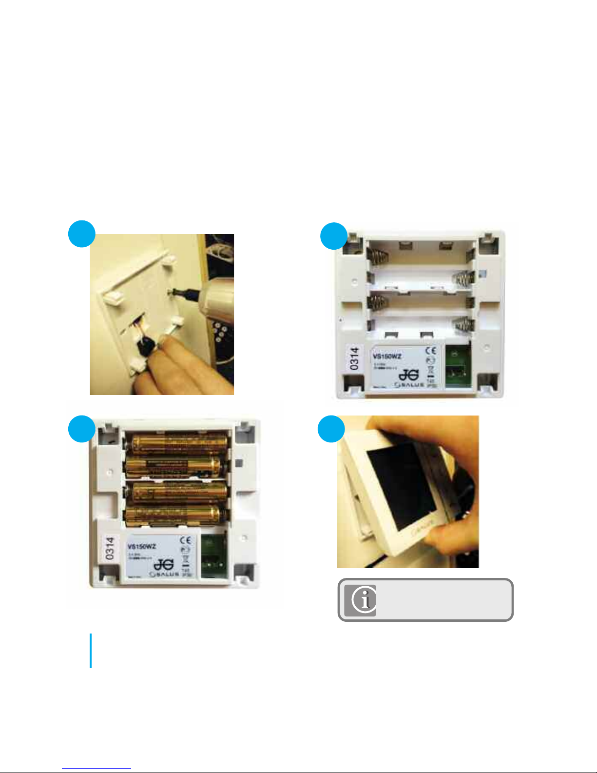
Once you have connected your choice of external sensor (if applicable).
Insert batteries
Note: Please proceed
to page 23.
16
JGSTATW Instruction Manual
1
2
3 4
Installation - Thermostat Mounting
(JGSTATW1)
Page 17
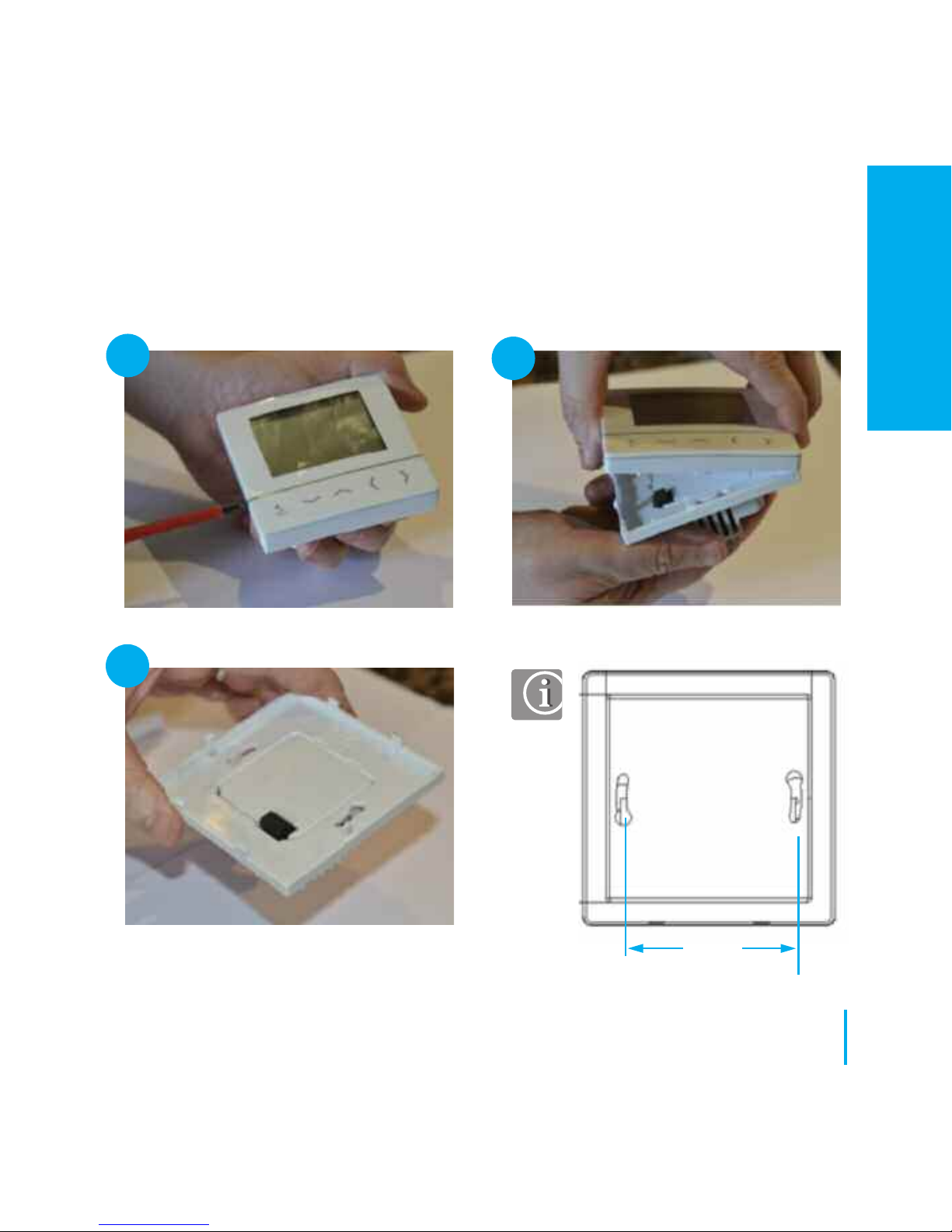
17
www.speedfitUFH.co.uk
Carefully remove the front housing.
60mm
Installation - Thermostat Mounting
(JGSTATW1)
1
2
3
Carefully remove the front housing.
INSTALLATION
Page 18
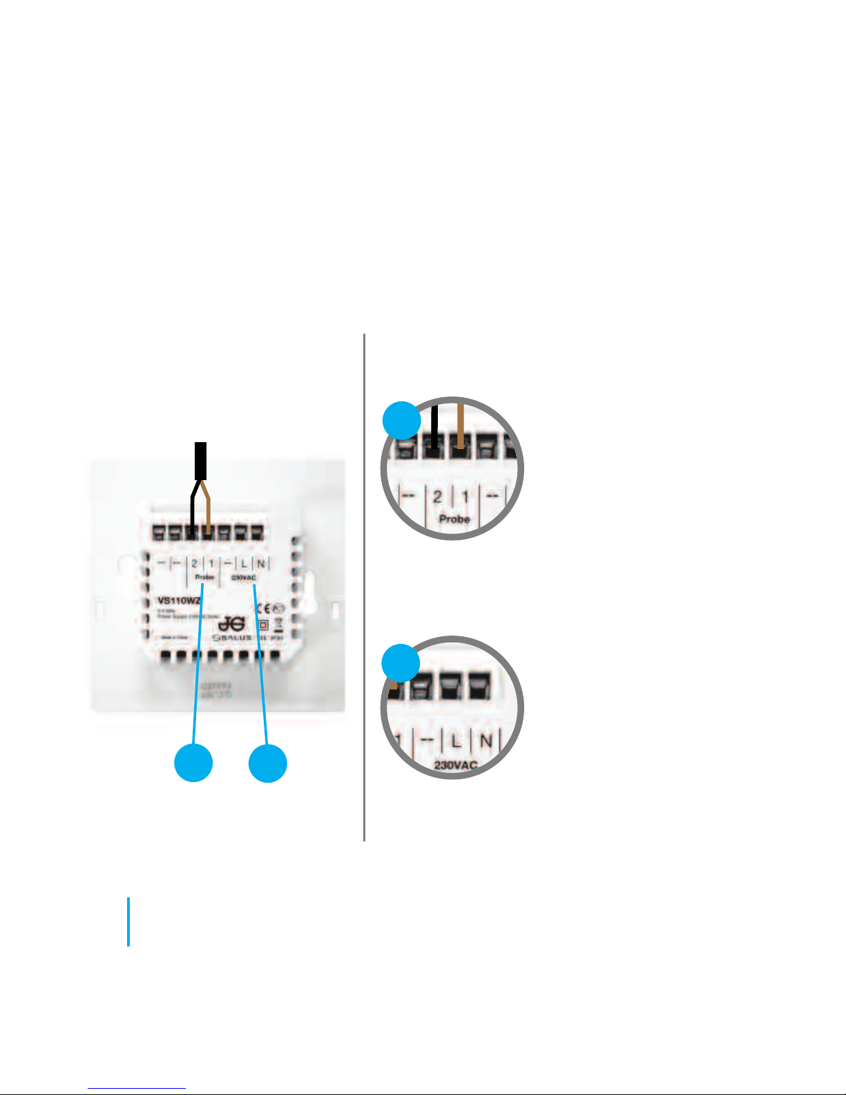
Rear of unit
Power Terminals 230v
AC.
Used for supplying
power to the unit. 230v
supply can be sourced
from the wiring centre or
any convenient source.
Sensor Terminals. Can
be used for external Air or
Floor sensor when
configured as thermostat.
Can also be used for
Cylinder thermostat
connection when
configured as a Timer.
18
JGSTATW Instruction Manual
Understanding your terminal connections
Installation - Terminal Connections
(JGSTATW2)
1
2
1
2
Page 19
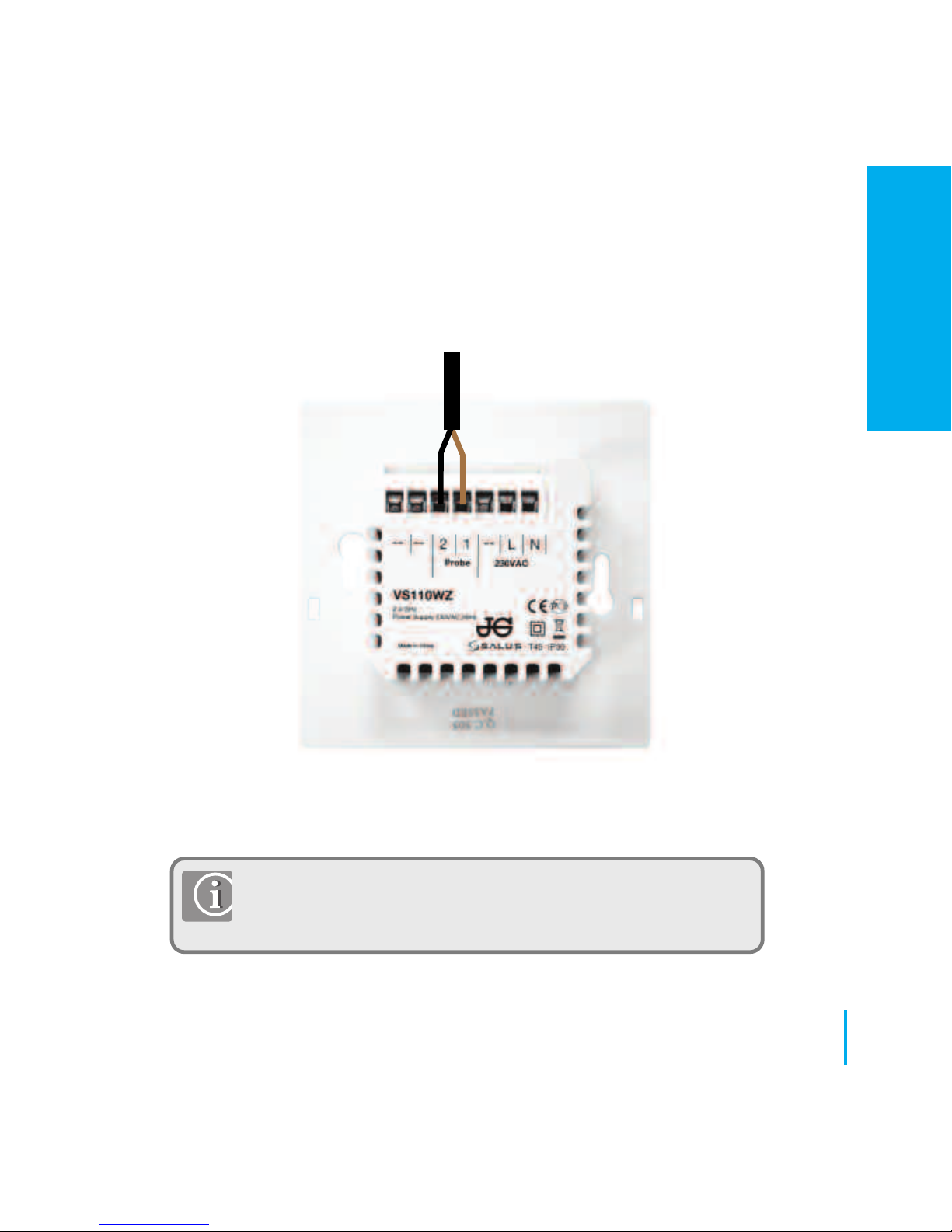
Note: If you are using an external sensor, the unit has to be
configured for External Air Sensor or Floor Protection Sensor.
Please see device parameter setting page 57.
Aura External sensor (Sold separately).
19
www.speedfitUFH.co.uk
Installation - Thermostat External Sensor (JGSTATW2)
INSTALLATION
Page 20
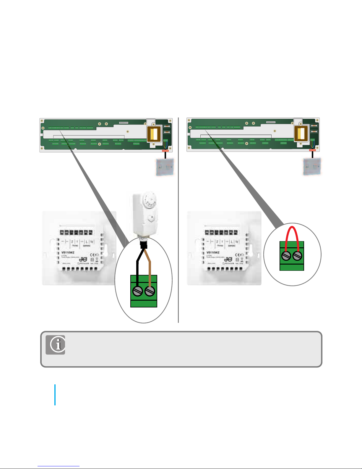
Note: Optional - The JGSTATW2 can be configured for connection to a cylinder
thermostat. Please see Device Parameters on page 57. For additional wiring
centre information refer to Wiring Centre Instruction Manual.
WC connected cylinder
thermostat (Default)
20
JGSTATW Instruction Manual
Installation - Hot Water Cylinder Thermostat (JGSTATW2)
ZONE 1
SL N L SL N L SL N L SL N L SL N L SL N L SL N LSL N L
ZONE 2 ZONE 3 ZONE 4 ZONE 5
ZONE 6 ZONE 7
ZONE 8
5 x 20mm
5 x 20mm
IN OUT
Cylinder thermostat
ZONE 1
SL N L SL N L SL N L SL N L SL N L SL N L SL N LSL N L
ZONE 2 ZONE 3 ZONE 4 ZONE 5
ZONE 6 ZONE 7
ZONE 8
5 x 20mm
5 x 20mm
IN OUT
Link must
be fitted
HW Timer connected
to cylinder thermostat.
Page 21
21
www.speedfitUFH.co.uk
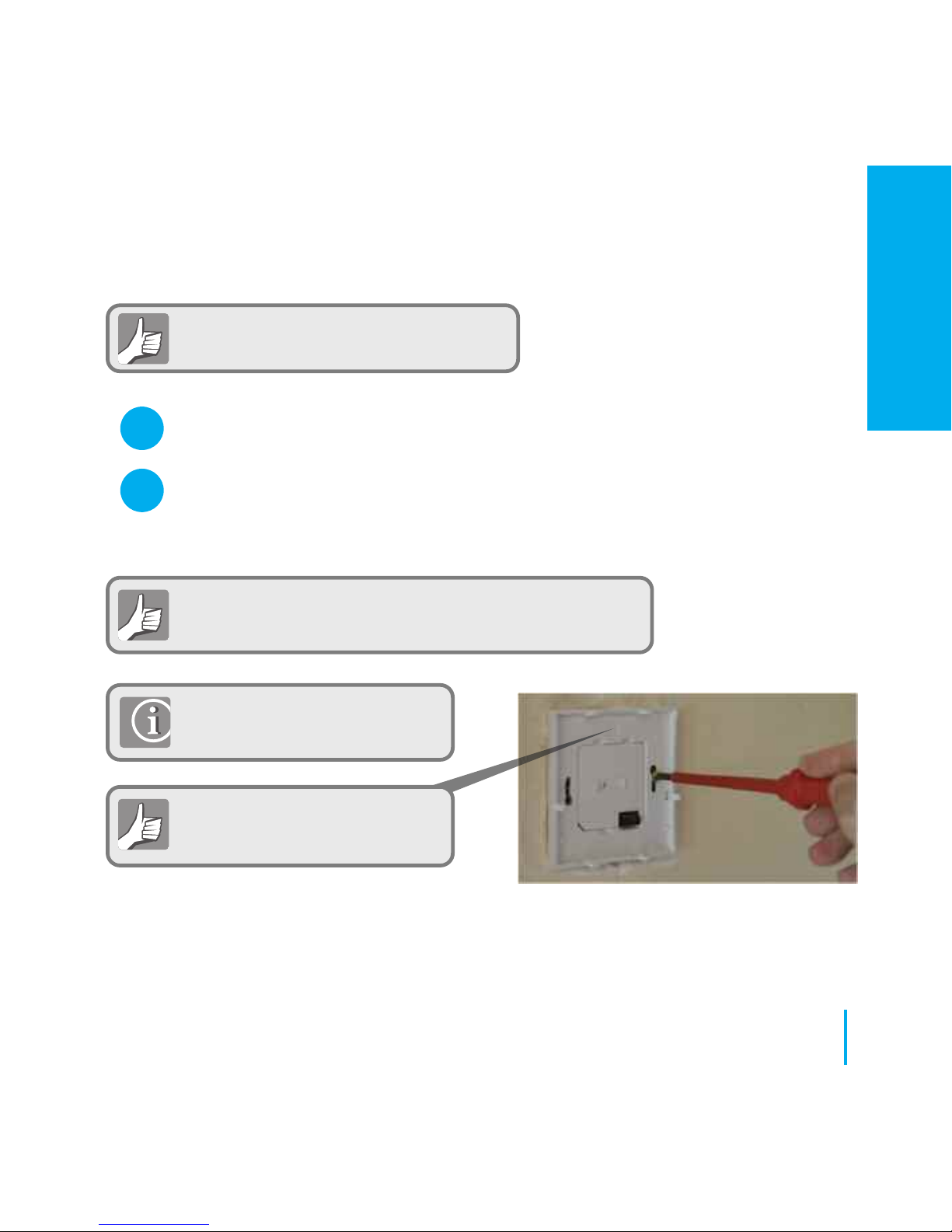
Check that the wiring is completed for:
Please use the screws provided.
Ensure the orientation arrow is
pointing upwards.
You are ready to secure the rear housing to the wall box.
Power Terminals
Sensor Terminals (if applicable)
Installation - Thermostat Mounting
(JGSTATW2)
1
2
INSTALLATION
Page 22
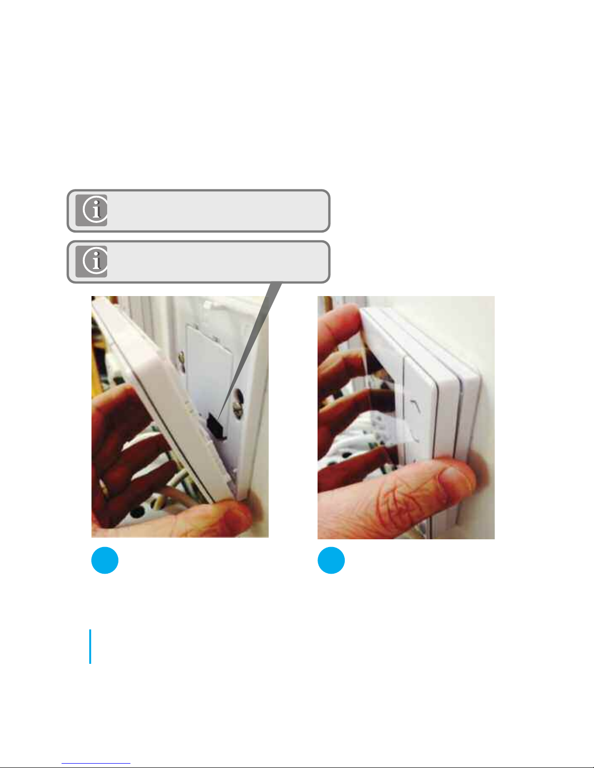
22
JGSTATW Instruction Manual
Installation - Thermostat Mounting (JGSTATW2)
Fit the front housing to the rear housing.
Align the front housing at
the bottom edge.
Lightly press until you
hear a positive click.
1 2
Ensure the pin connections are aligned.
Page 23
23
www.speedfitUFH.co.uk
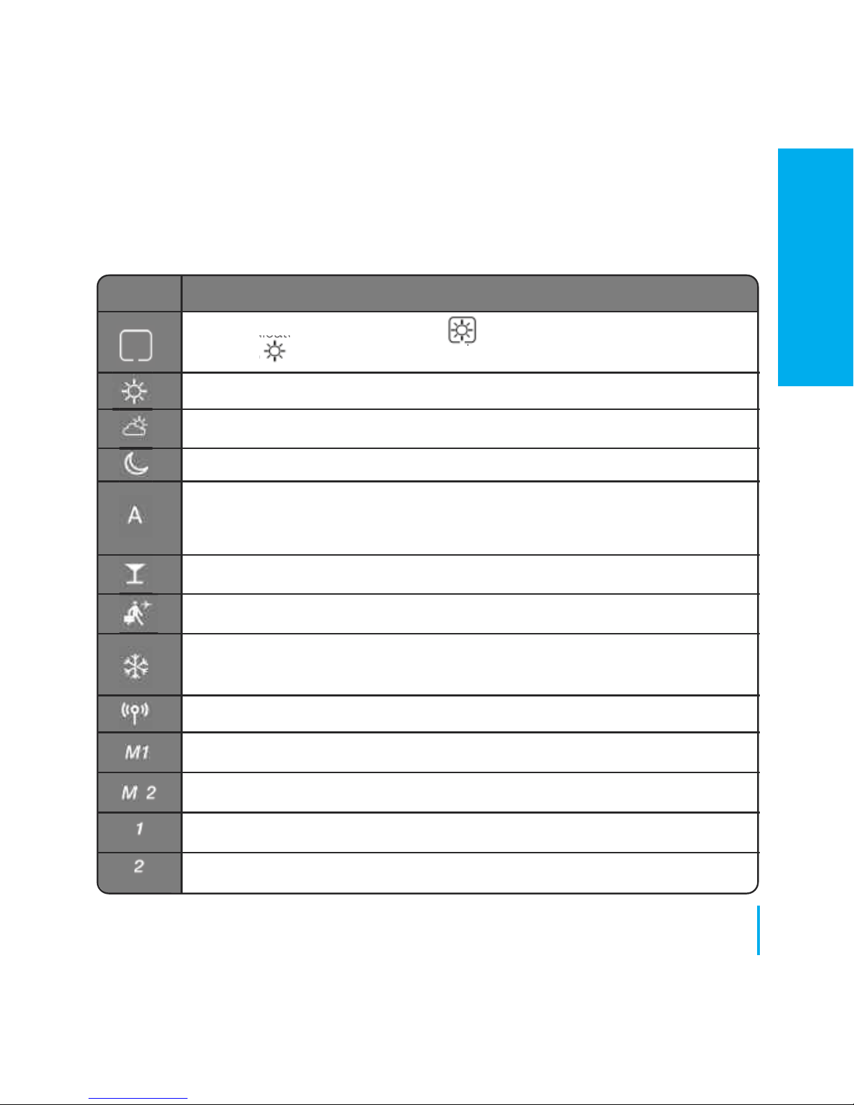
Installation - LCD Graphics
ICON FUNCTION
Box: Indicates selected mode e.g. means the current setpoint is
Hi temp, means the Hi temp is not selected.
Sunny: High comfortable temperature.
Cloudy: Middle comfortable temperature.
Moon: Low comfortable temperature.
Programmable Thermostat program mode indicator: Indicates program is
running, Auto On or Auto Off. For group thermostat this indicates that it is a
member of a group.
Party indicator:
When Party mode is active.
Holiday indicator:
When Holiday mode is active
Frost protection indicator:
Frost protection is active, not available in cooling
mode (if applicable)
RF Transmission is active
Group 1 Control Thermostat
Group 2 Control Thermostat
Group 1 Thermostat
Group 2 Thermostat
INSTALLATION
Page 24
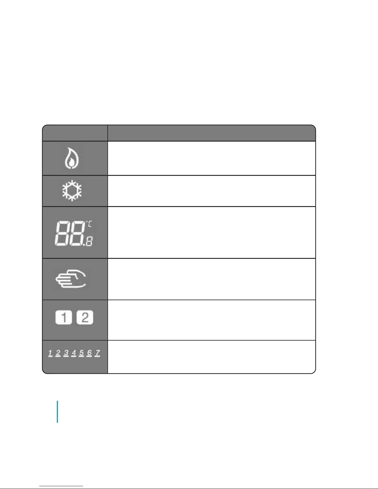
ICON FUNCTION
Heat indicator: Indicates demand for heat.
Cool mode indicator: Indicates cooling is required
(if applicable)
Temperature indicator:
Displays room temperature,
Set-temperature,
or other information.
Temporary manual override indicator: If the set
temperature is changed when in program mode,
the hand will appear until the next program start time.
Programs number indicator: Displayed in AUTO mode or
Temporary Override. The number indicates which program
is running.
Day indication: 1 = Monday
24
JGSTATW Installer Manual
Installation - LCD Graphics
Page 25
25
www.speedfitUFH.co.uk
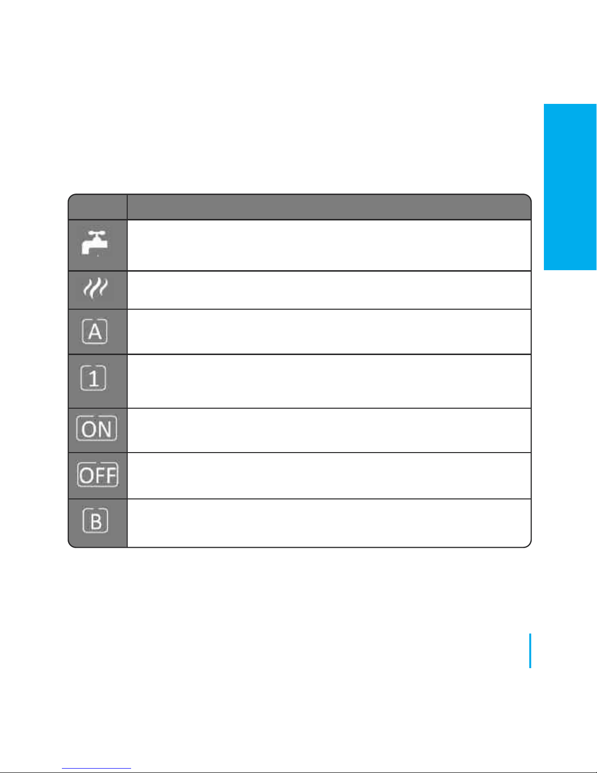
Installation - LCD Graphics
ICON FUNCTION
Hot Water (HW) indicator: Unit operating as a Hot Wwater Timer
Hot Water (HW) indicator: Indicates demand for Hot Water.
HW Program mode indicator: Indicates program is running.
HW Mode indicator: Mode for 1 period of HW a day, from
Program 1 ON to Program 3 OFF.
HW Mode indicator: Hot water switched on (continuously).
HW Mode indicator: Hot water switched off (continuously).
HW Mode indicator: Indicates Boost +1hr override.
INSTALLATION
Page 26
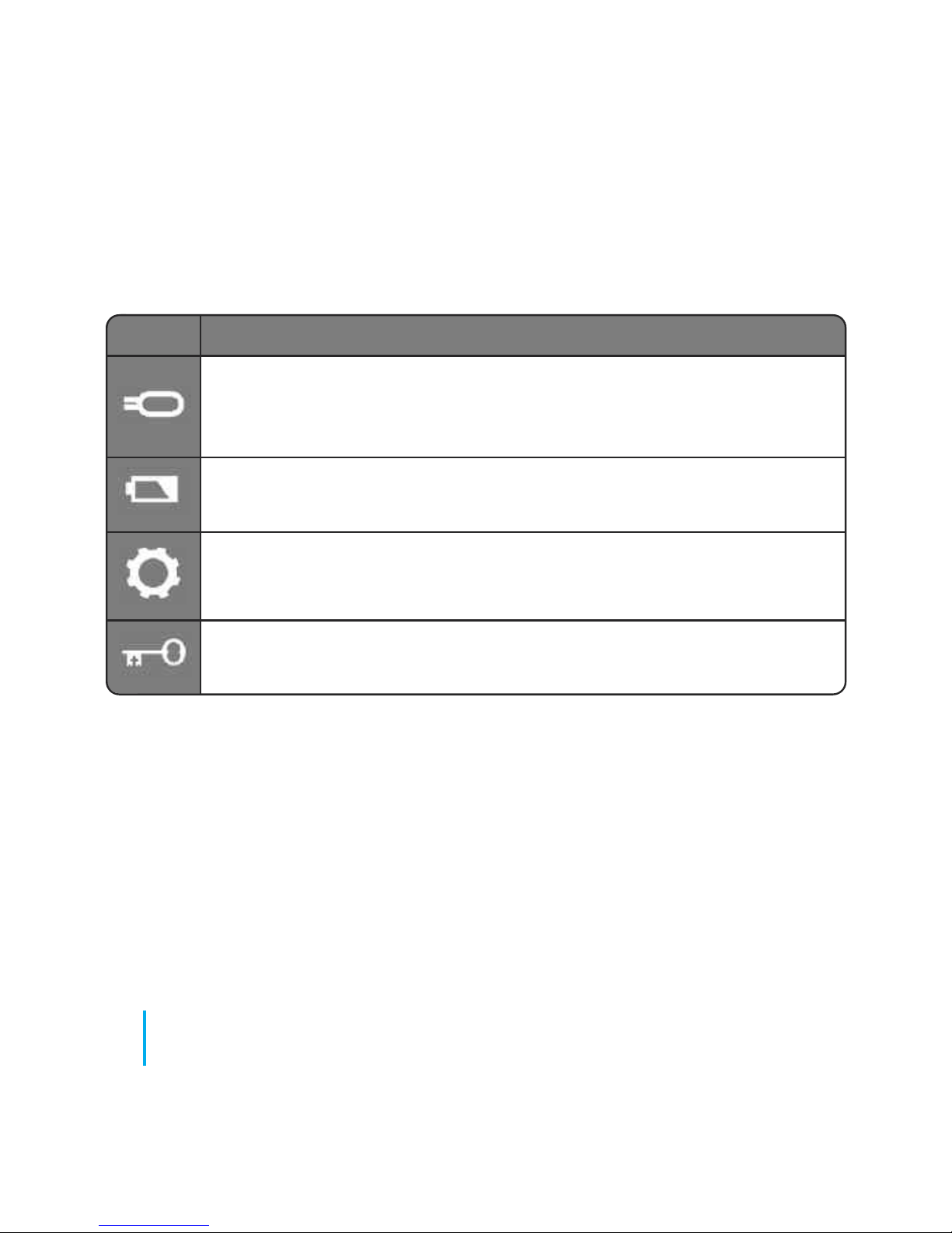
26
JGSTATW Instruction Manual
Installation - LCD Graphics
ICON FUNCTION
Floor sensor probe indicator: Show only when Air + Floor
sensor is connected.
Low battery indicator: Batteries need to be replaced.
Setting indicator: Indicates the unit is inprogram setting mode.
Keylock indicator: Keys have been deactivated.
Page 27
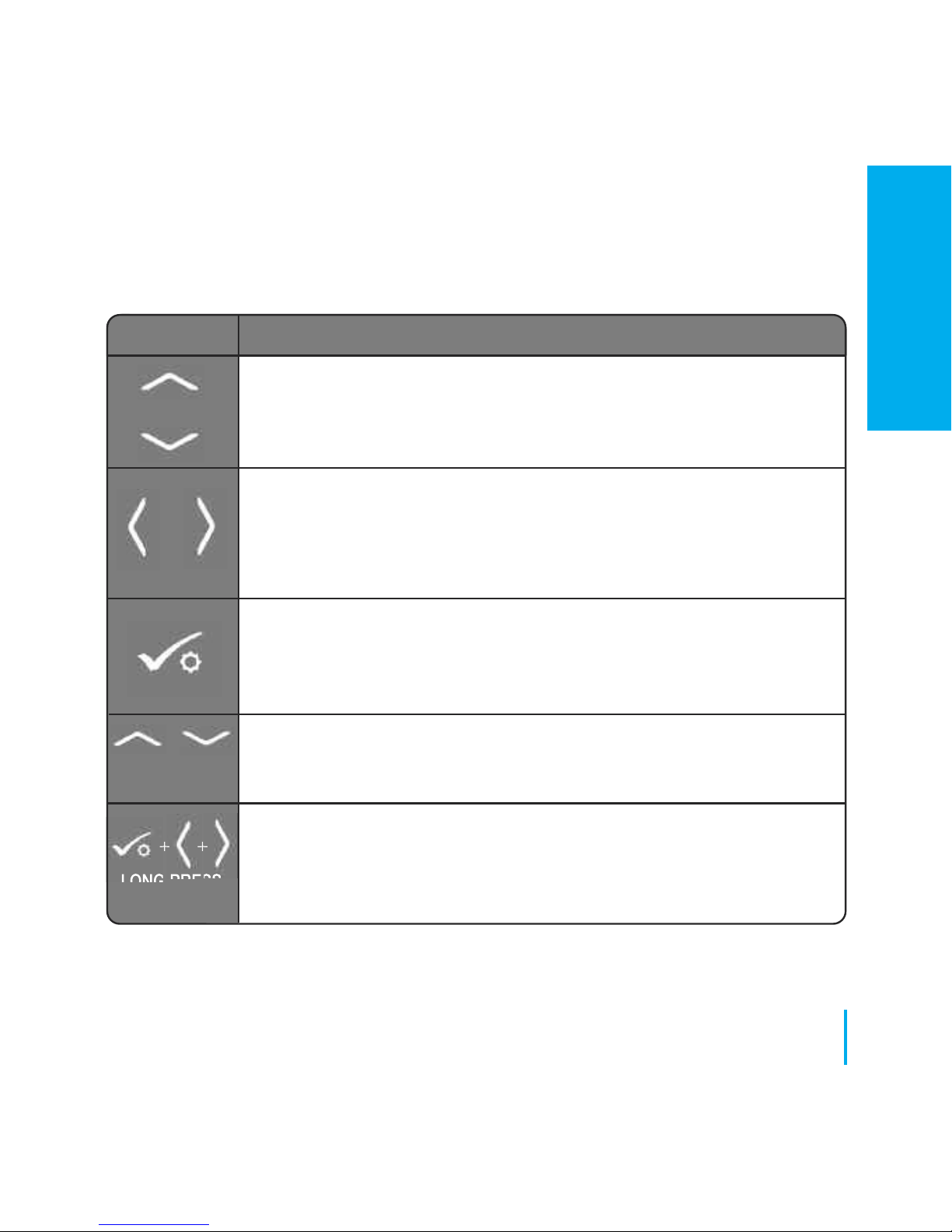
KEY FUNCTION
1. Increase or decrease setpoint temperature.
2. Increase or decrease Day, Clock, Timer, Party, Holiday and Boost.
3. Select installer parameter value.
1. Mode selection.
2. Long press to return to home display without saving.
3. Short press to return to the previous screen when it is in
user/installer setting mode.
1. OK key: Short press to confirm selection.
2. Long press to save and exit.
3. Long press to enter the user settings.
Lock/Unlock
Enter Installer parameter settings
OR
+
++
LONG PRESS
LONG PRESS
OR
27
www.speedfitUFH.co.uk
Installation - User Interface
INSTALLATION
Page 28
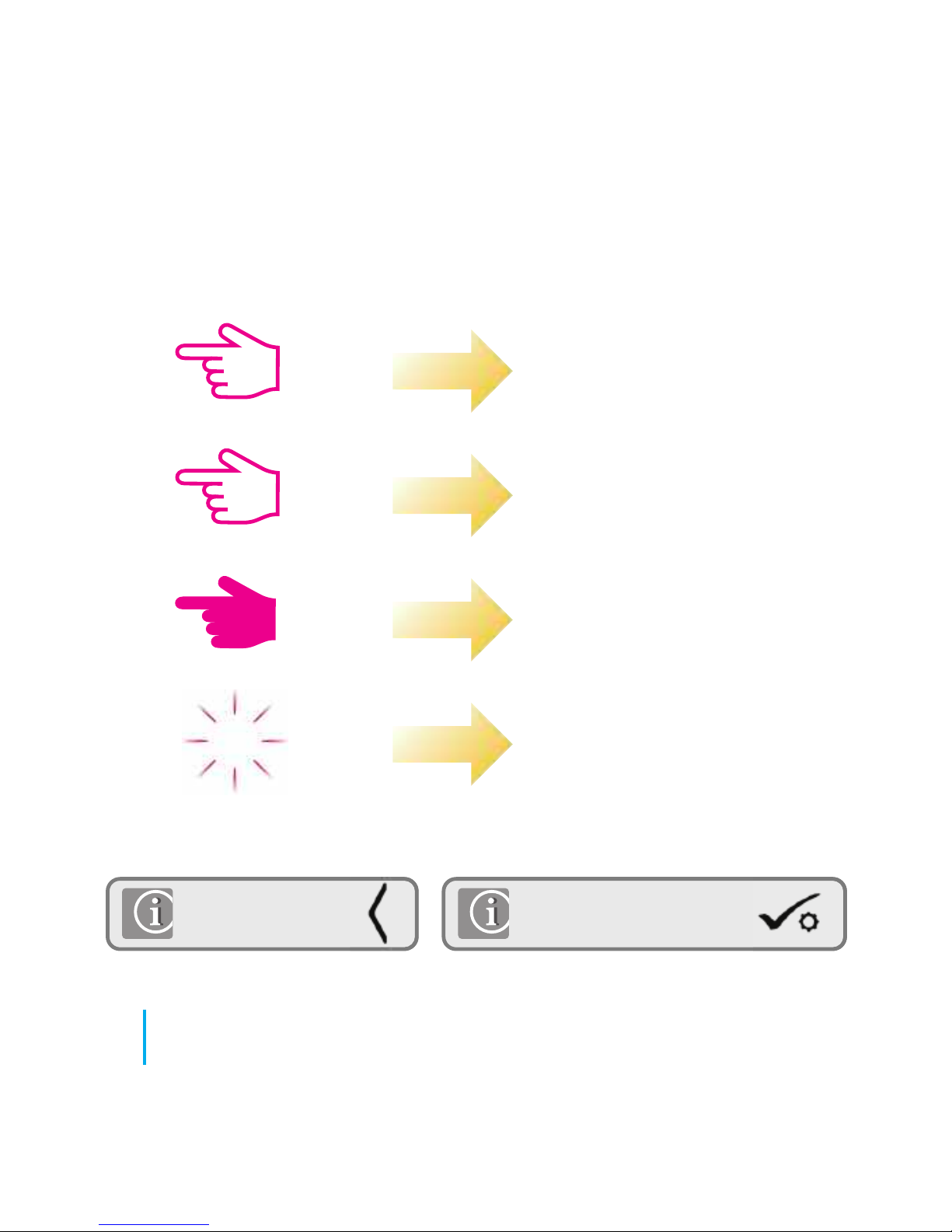
Press once
Press x amount of times
Hold for five seconds
Flashing
xx
Short press to save and
long press to save and exit
Short press to
back up
28
JGSTATW Instruction Manual
Installation - Graphics Key
Page 29
29
www.speedfitUFH.co.uk
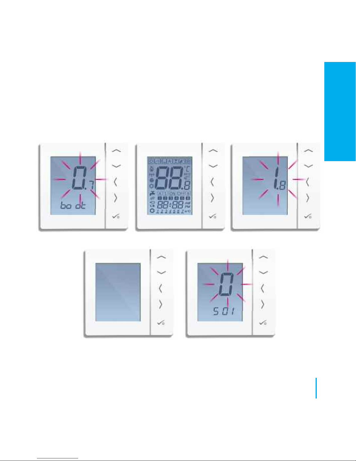
Installation - First Power Up
INSTALLATION
Page 30
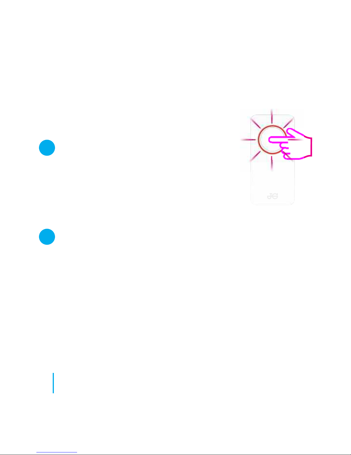
System setup checklist
The Wireless coordinator must be in pairing mode.
Before starting the pairing, make sure the light is
flashing on the coordinator by holding the button for 5
seconds. For more information refer to the Coordinator
Instruction Manual.
The device that you intend to pair with must be
ready to accept pairing.
Please refer to pages 33 - 45 and the relevant device
Instruction Manuals.
30
JGSTATW Instruction Manual
Installation - System Setup
1
2
Page 31
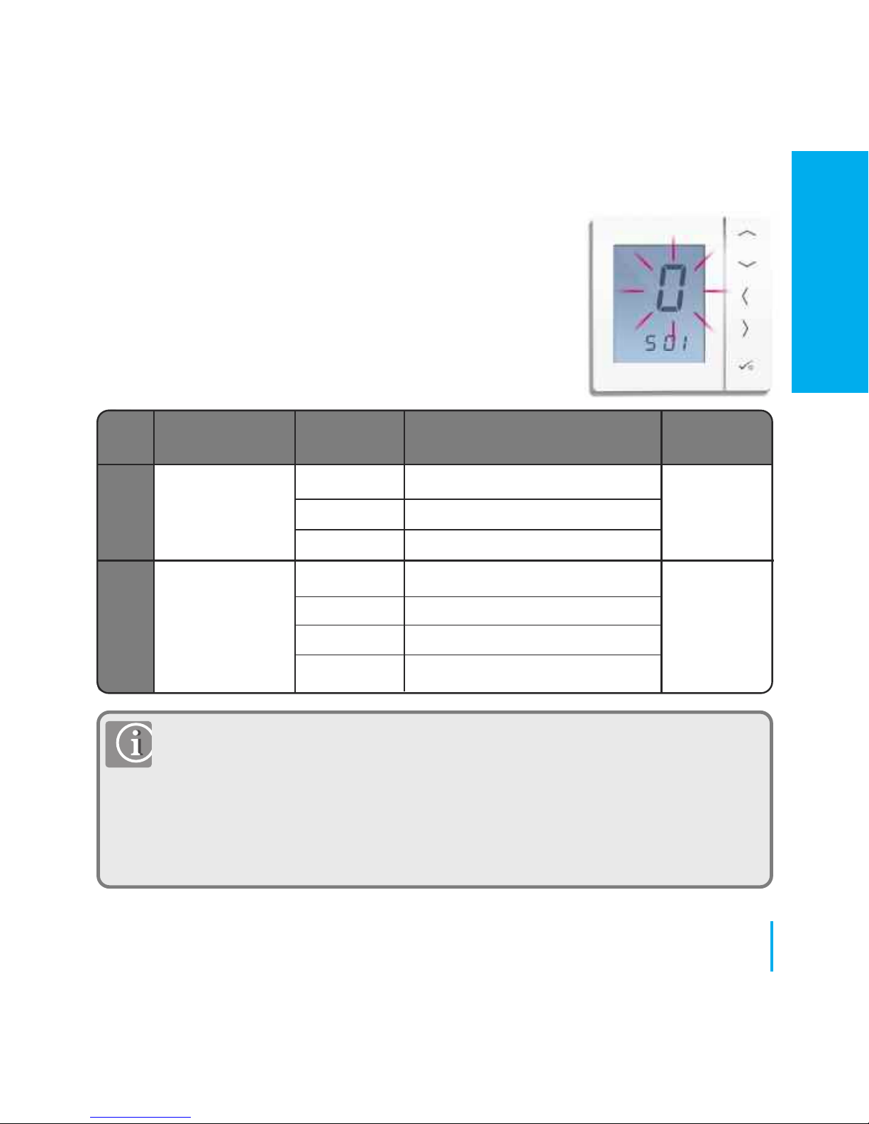
You are now ready to configure the unit using the
system parameter table below.
*Grouping requires a wiring centre. Please refer to page 6. Additionally you must
have a PRT for grouping to operate. Two groups are the maximum allowed per
wiring centre.
** This setting is used when there is only a system receiver only in the system. If
there is a system receiver set to RX1 used along with wiring centre, radiator valves
and system receiver set to RX2 then RX1 will communicate automatically to the
thermostat connected to these other devices.
31
www.speedfitUFH.co.uk
Installation - System Parameters
SX FUNCTION SYSTEM DEFINITION DEFAULT
SETTING
System Unit
0 Programmable Stat (PRT)
S01
Type
1 Digital Thermostat 0
2 HW Timer
What does unit 0* Aura Wiring Centre*
S02
Communicate 1 Aura radiator valve 0
with in the Aura 2 System Receiver set for RX2
system 3** System Receiver set to RX1**
INSTALLATION
Page 32
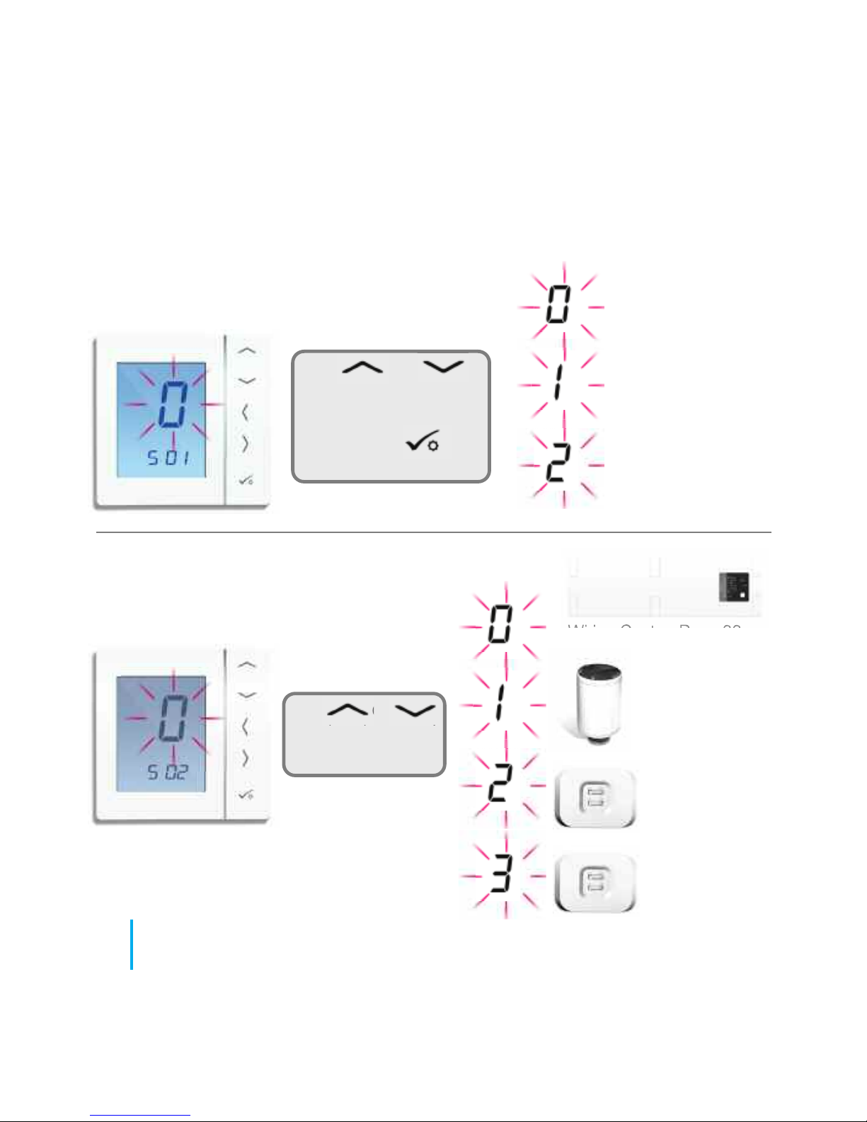
Selecting unit type.
Selecting what device to pair with
Use or
to select the type of unit.
After selection has been
made, press
to confirm.
Use or
to select the type of
device to pair with.
Programmable
Thermostat (PRT)
Digital Thermostat
HW Timer
Wiring Centre. Page 33
Radiator Valve.
Page 37
Single Room
Receiver (RX2).
Page 41
Boiler Receiver
only (RX1).
Page 44
32
JGSTATW Instruction Manual
Installation - System Setup
Page 33
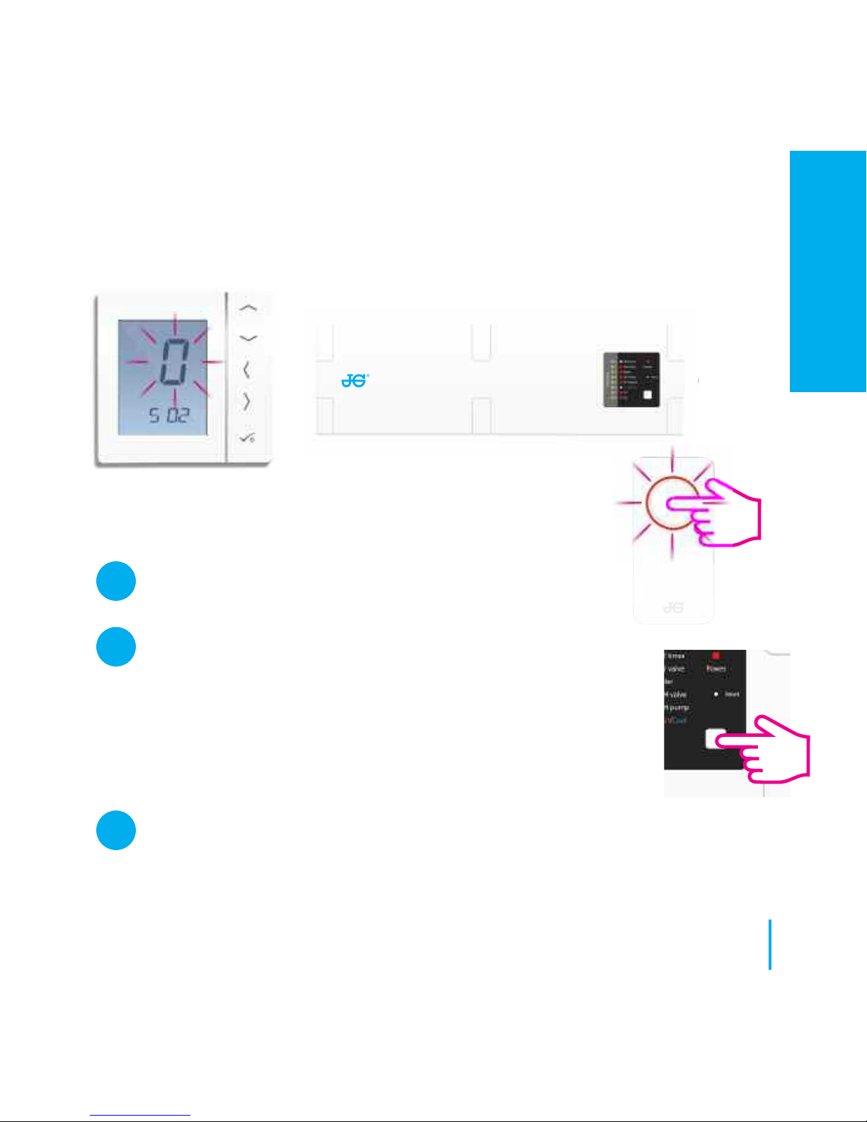
Wiring
Centre
Checklist
The Wireless Coordinator must be in pairing mode.
Ensure the wiring centre and optional system receiver
(Configured to RX1) for remote boiler switch are powered up.
Note: The wiring centre and system receivers will automatically
join the Zigbee network when powered up and the Wireless
Coordinator is in pair mode. Red LED on Wiring Centre and RX1
will go steady when the devices have joined the Zigbee network.
If more than one wiring centre is in the system, establish and note the wiring centre
number by pressing the network key for 1 second. The wiring centre number will
flash.
33
www.speedfitUFH.co.uk
1
2
3
Installation - Pairing with Wiring Centre
INSTALLATION
Page 34
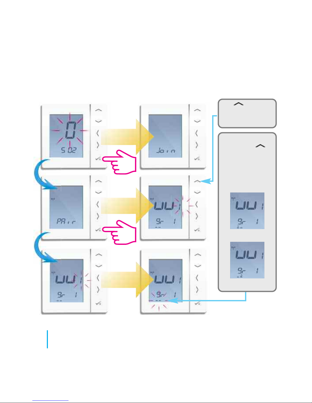
Use to select
the wiring centre
number to pair with.
34
JGSTATW Instruction Manual
Installation - Pairing with Wiring Centre
If you are using
groups, use
to select group
number of each
group required. If
unit is stand alone
then please select --
Group 1
Group 2
Page 35
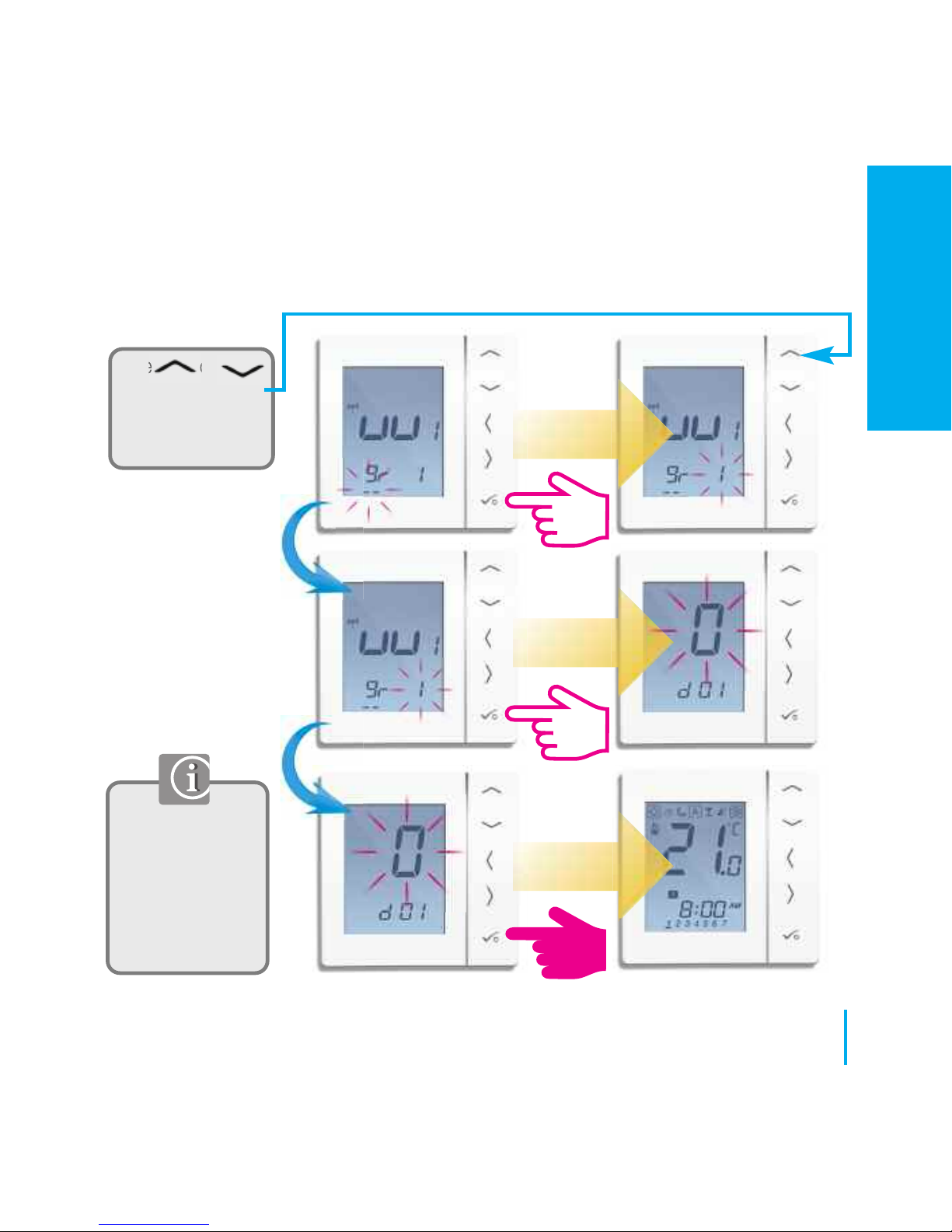
Long press to exit
to home screen
or continue to
change device
settings. Refer to
page 57.
Use or
to select the
wiring centre zone
number 1 to 8.
35
www.speedfitUFH.co.uk
Installation - Pairing with Wiring Centre
INSTALLATION
Page 36
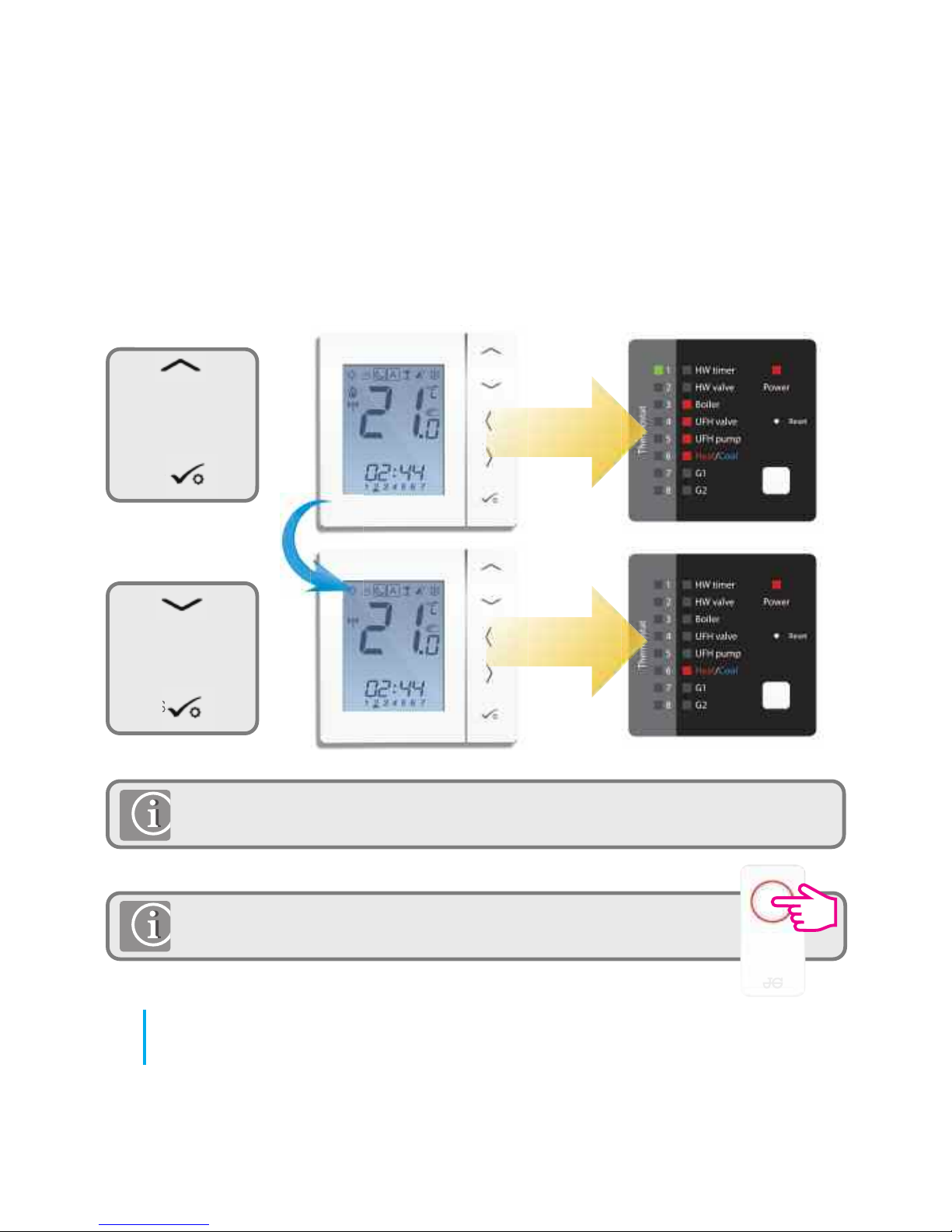
Use to
increase
temperature to
30ºC and then
press
Use to
decrease
temperature to
10ºC and then
press
If you are using the optional system receiver configured to RX1 please check that
the green light goes on when the temperature is raised and off when reduced.
If pairing for your system is complete, please take the Coordinator
out of pair mode. Press for 5 seconds and light will stop flashing.
36
JGSTATW Instruction Manual
Installation - Testing the pairing with the JGWCW
Page 37
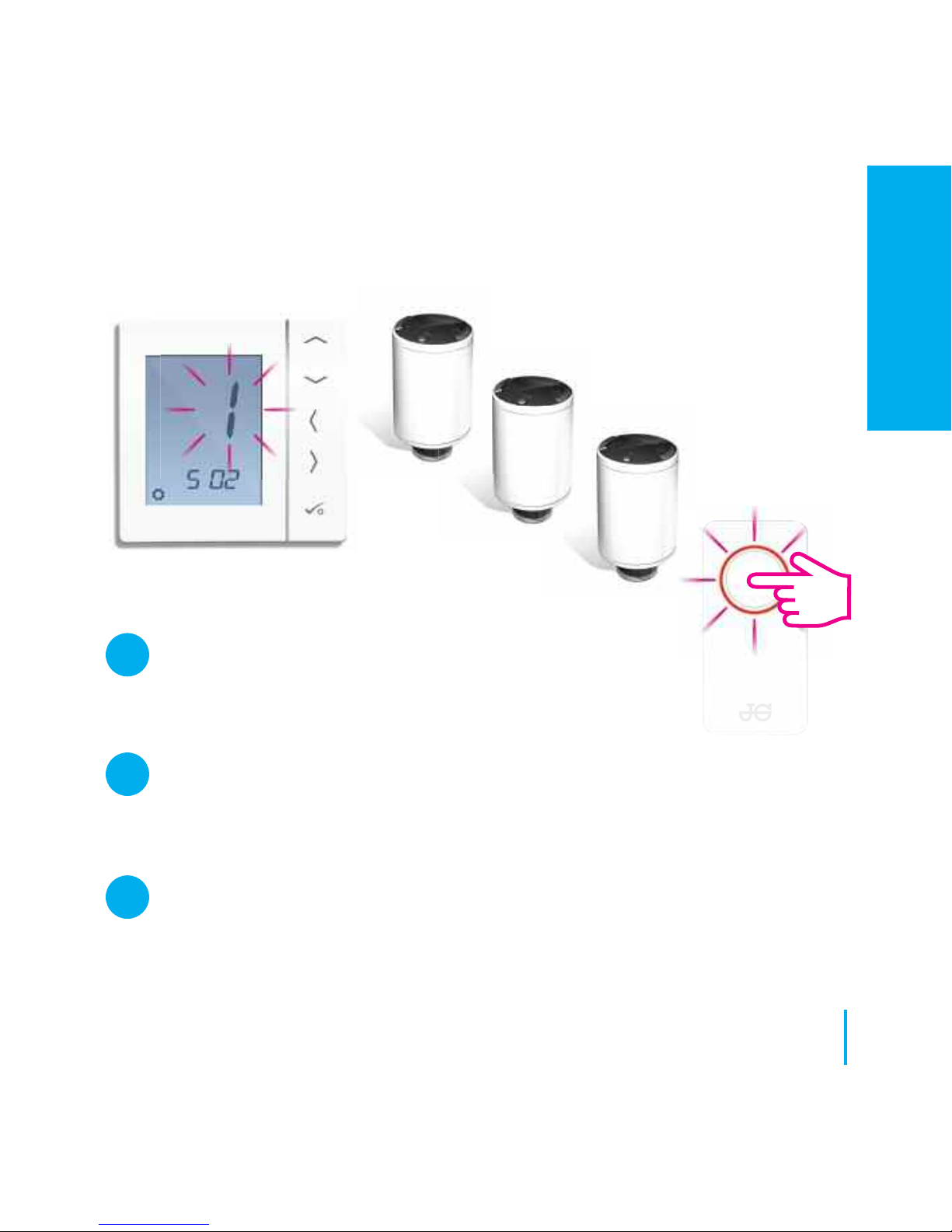
Radiator
Valves
Checklist
The Wireless Coordinator must be in pairing mode.
Ensure that the radiator valves are in pairing mode (Refer to JGTRV Instruction
Manual). A maximum of 3 radiator valves can be paired with each thermostat.
Please pair TRV’s on a room by room basis.
If you are using the optional system receiver configured to RX1 for remote
boiler switching, ensure this has been powered up and the red flashing LED
has gone steady.
37
www.speedfitUFH.co.uk
1
2
3
Installation - Pairing the Radiator Valve(s)
INSTALLATION
Page 38
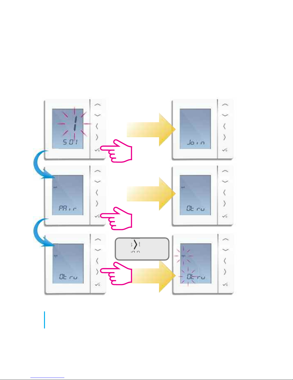
Press to start the
pairing process.
38
JGSTATW Instruction Manual
Installation - Pairing with Radiator Valve
Page 39
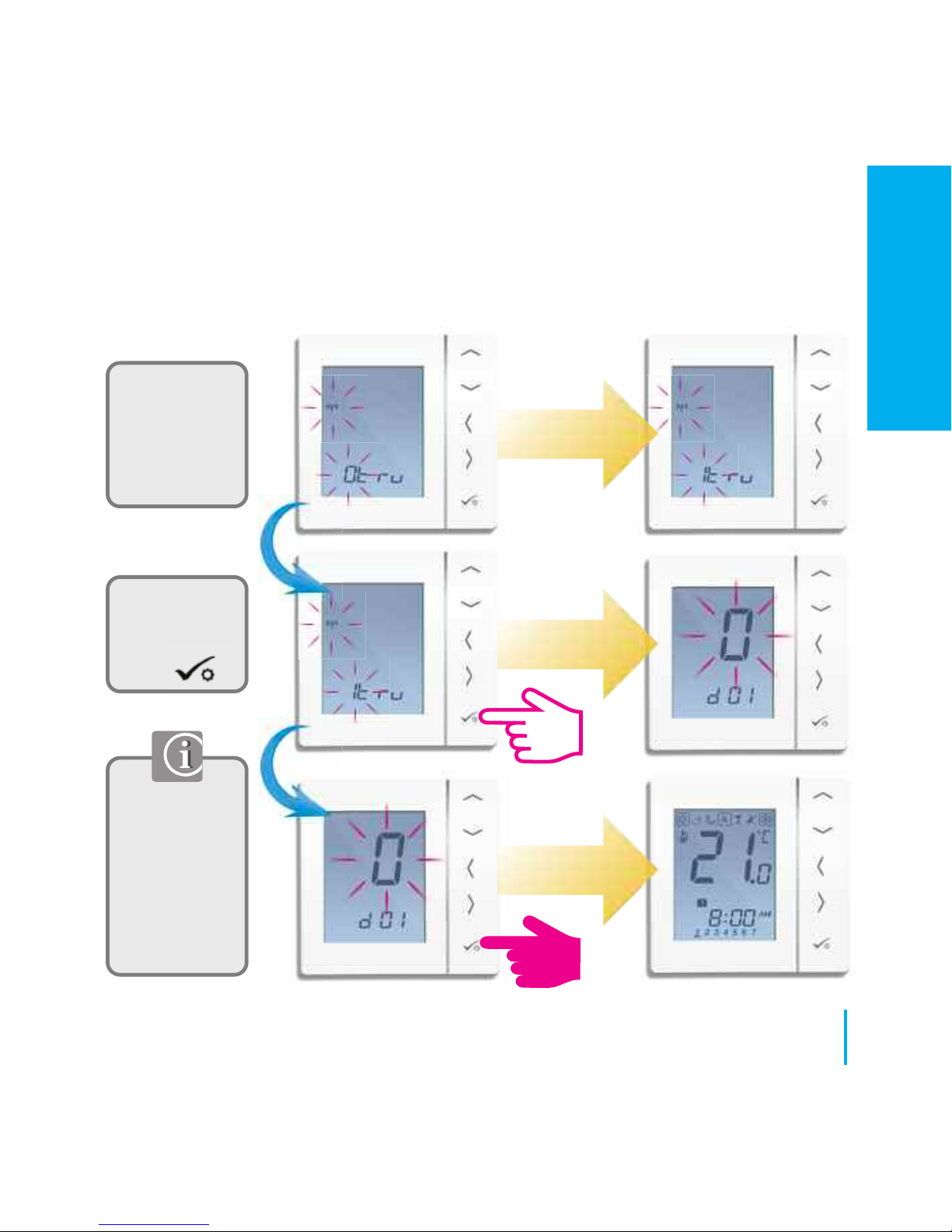
Long press to
exit to home
screen or
continue to
change device
settings. Refer
to page 57.
Once all
TRV’s have
paired
press
The prefix
number on the
TRV will
change as the
TRV(s) pair.
39
www.speedfitUFH.co.uk
Installation - Pairing with the Radiator Valve
INSTALLATION
Page 40
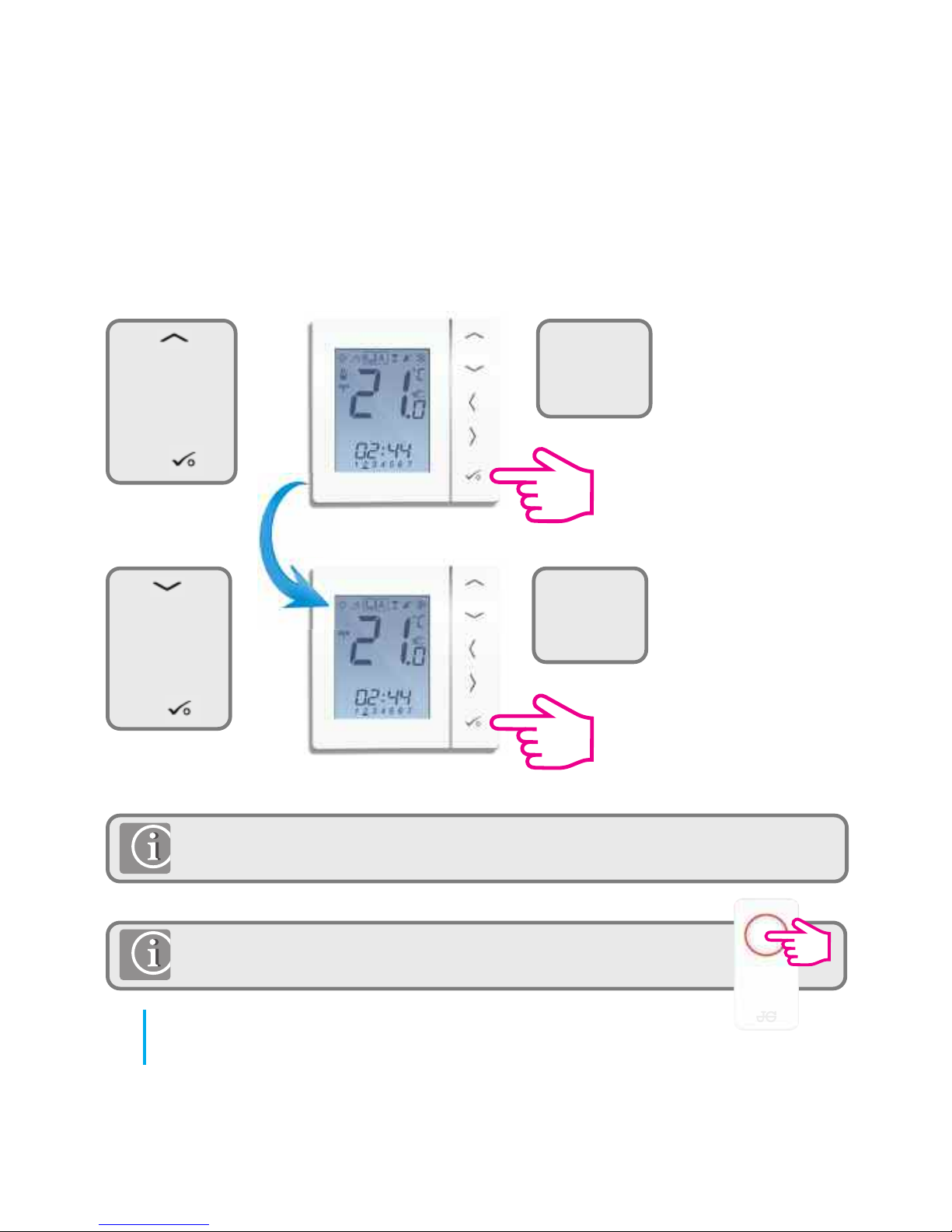
Use to
increase
temperature
to 30ºC
and then
press
Use to
decrease
temperature
to 10ºC
and then
press
If you are using the optional system receiver configured to RX1 please check that
the green light goes on when the temperature is raised and off when reduced.
If pairing for your system is complete, please take the coordinator
out of pair mode. Press for 5 seconds and light will stop flashing.
40
JGSTATW Instruction Manual
Installation - Testing Wireless Pairing
You should
hear the
valve open.
You should
hear the
valve close.
Page 41
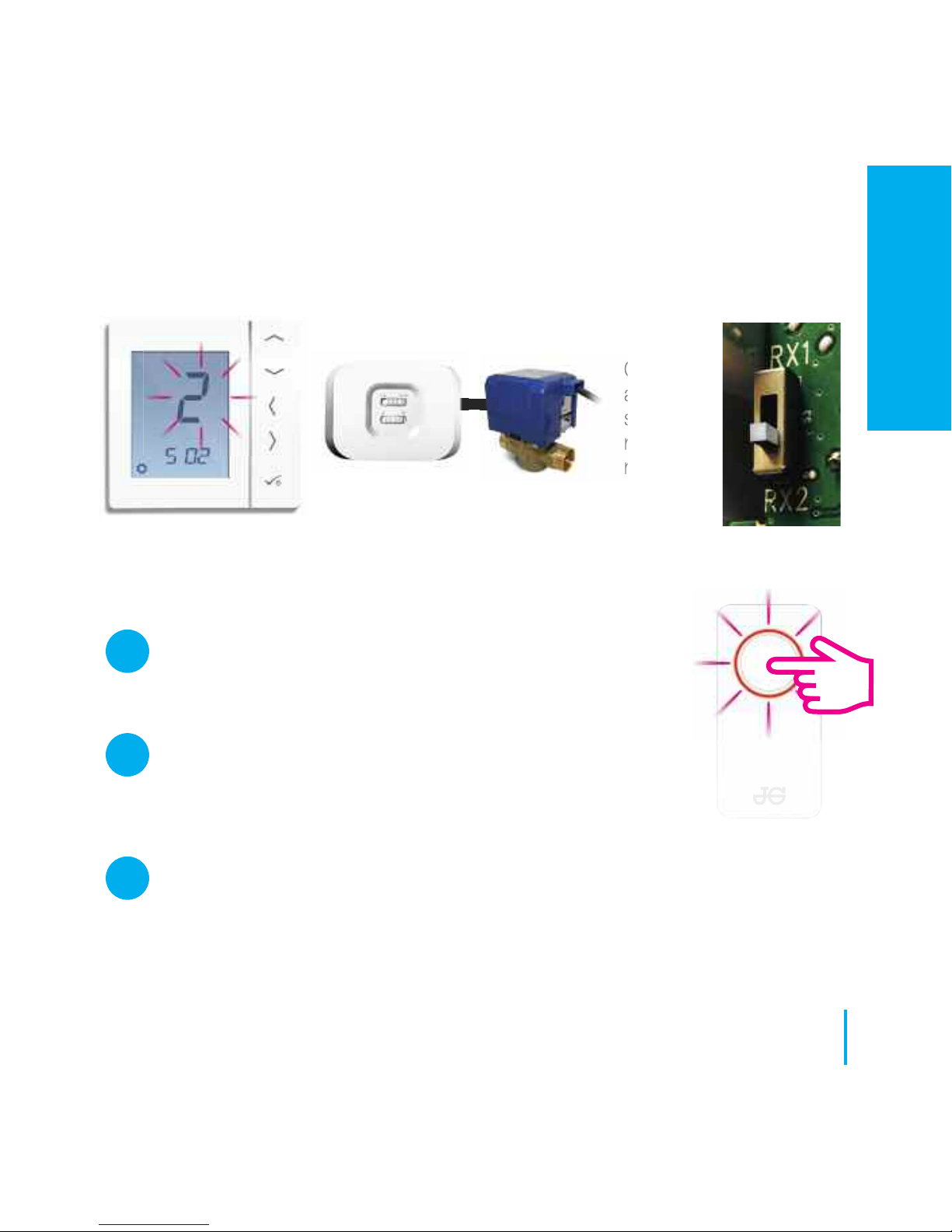
JGBR
Configured
as RX2
single
room
receiver.
Checklist
The Coordinator must be in pairing mode.
The JGBR (set to RX2) is powered up and the red LED is
steady. Refer to JGSTATW Instruction Manual.
If you are using the optional JGBR configured to RX1 for remote boiler
switching, ensure this has been powered up and the red flashing LED has
gone steady. Refer to JGBR Instruction Manual.
Refer to JGBR
Instruction Manual.
41
www.speedfitUFH.co.uk
Installation - Pairing with Single Room Receiver
1
2
3
INSTALLATION
Page 42
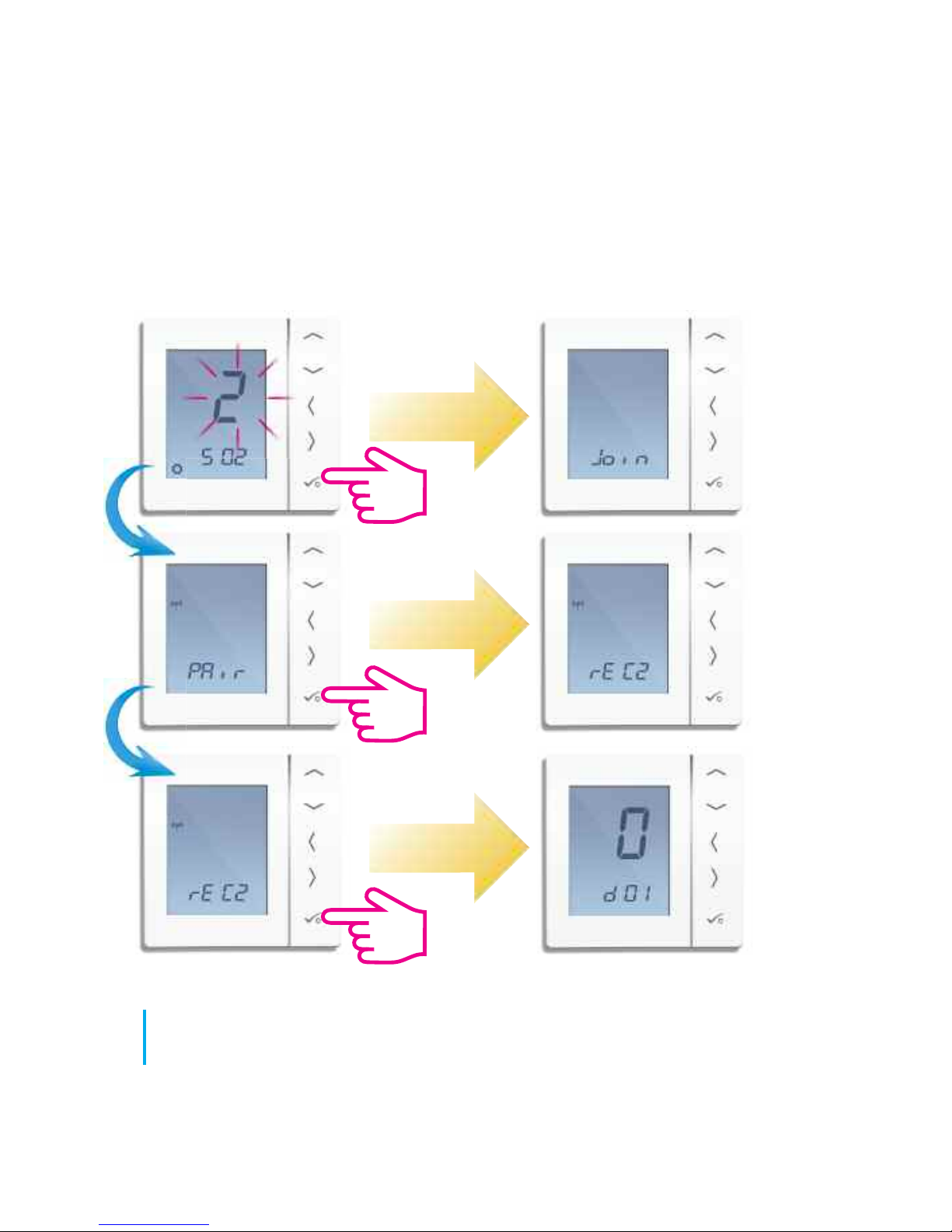
42
JGSTATW Instruction Manual
Installation - Pairing with Single Room Receiver
Page 43
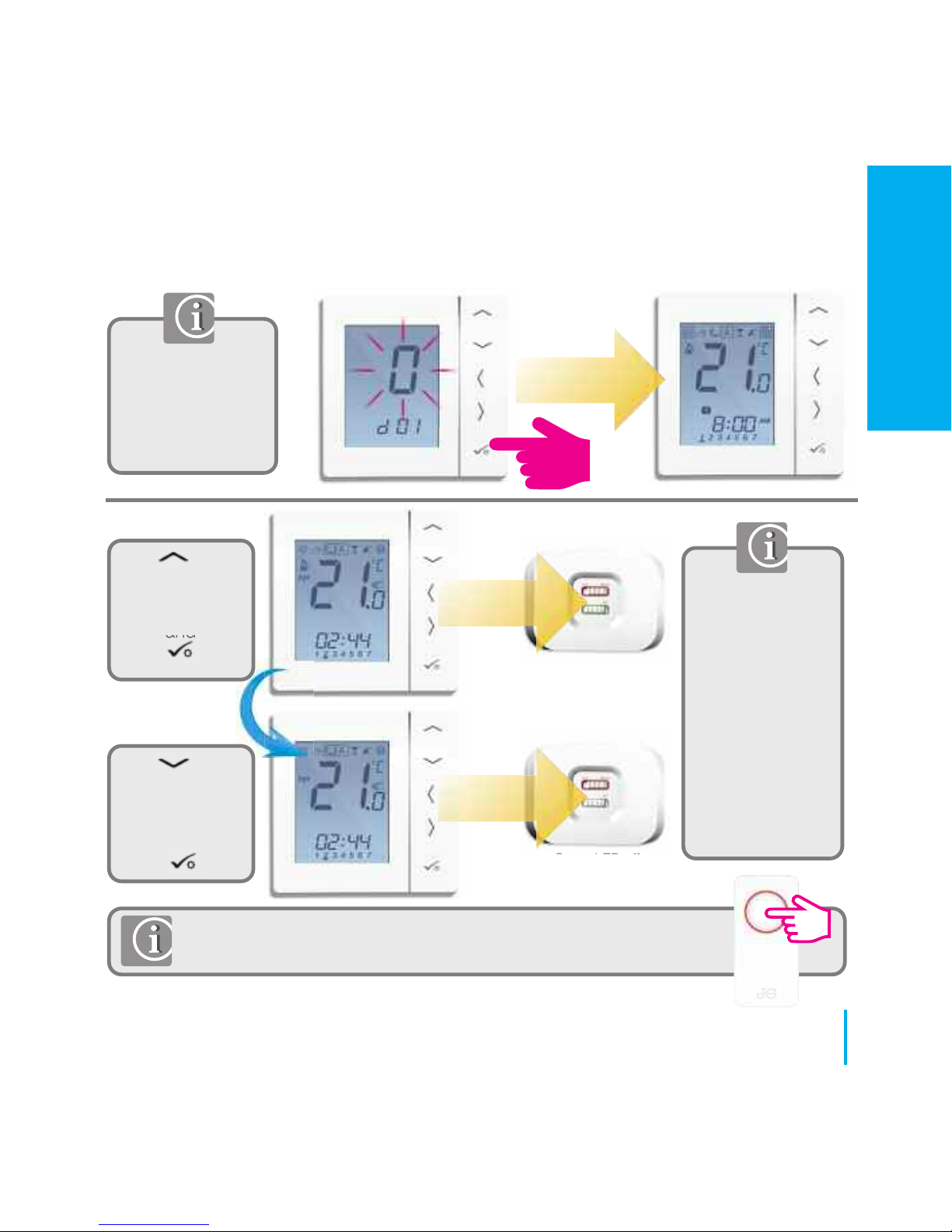
Long press to exit
to home screen or
continue to change
device settings.
Refer to page 57.
Use
to increase
temperature to
30ºC and then
press
Green LED on
Green LED off
Use to
decrease
temperature to
10ºC and then
press
If you are using
the optional
system receiver
configured to RX1
please check that
the green light
goes on when the
temperature is
raised and off
when reduced.
If pairing for your system is complete, please take the Coordinator
out of pair mode. Press for 5 seconds and light will stop flashing.
43
www.speedfitUFH.co.uk
Installation - Testing Pairing with Single Room Receiver
INSTALLATION
Page 44
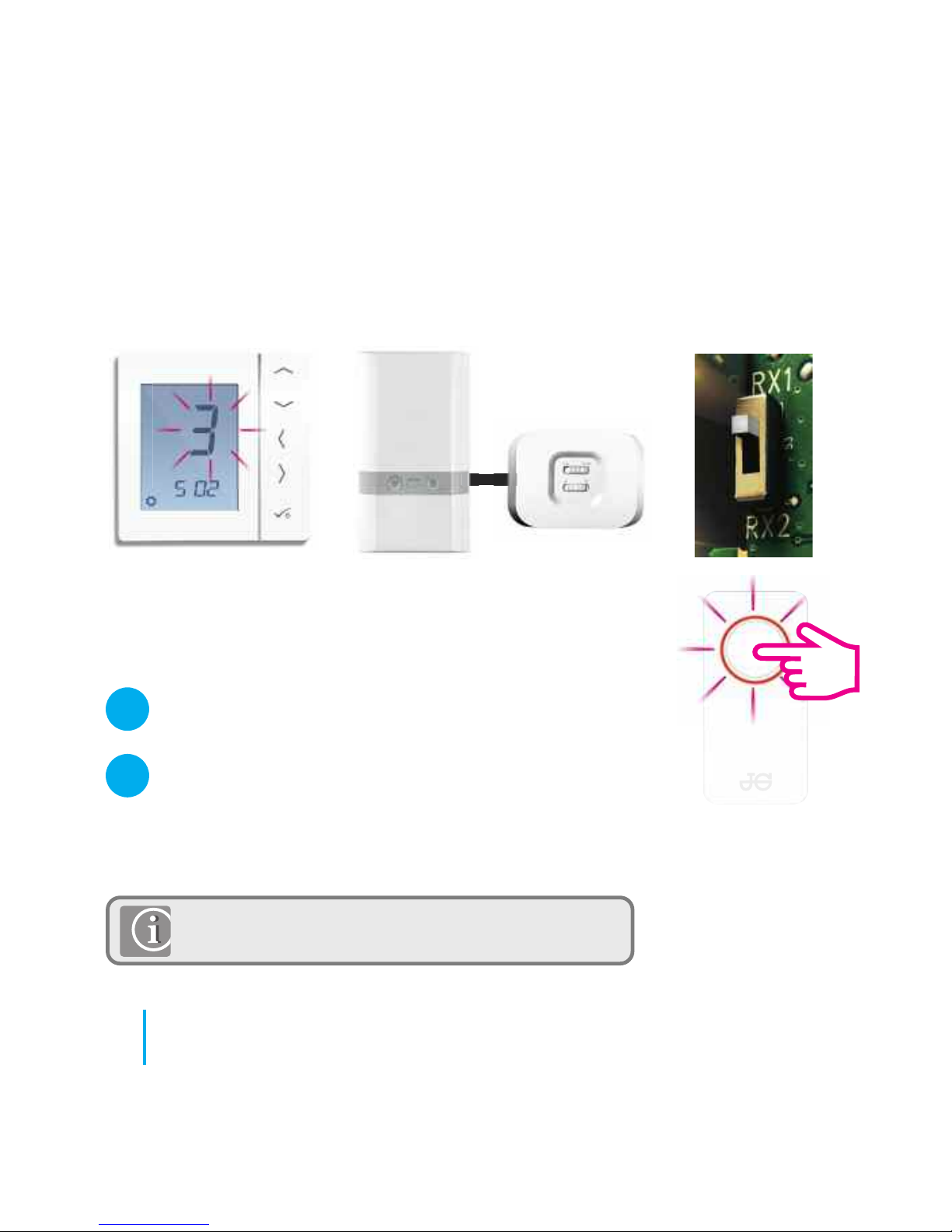
Checklist
The coordinator must be in pairing mode.
The system receiver (set to RX1) is powered up and
the red LED is steady. The Boiler Receiver will auto join
the Zigbee network on power up when the Wireless
Coordinator is in Pairing mode.
System Receiver configured to
boiler receiver RX1. Refer to Boiler
Receiver Instruction Manual.
This configuration option is applicable if there is only
a Boiler Receiver RX1 in the system.
Used if system receiver is installed on its own.
44
JGSTATW Instruction Manual
1
2
Installation - Pairing with Boiler Receiver Only
Page 45
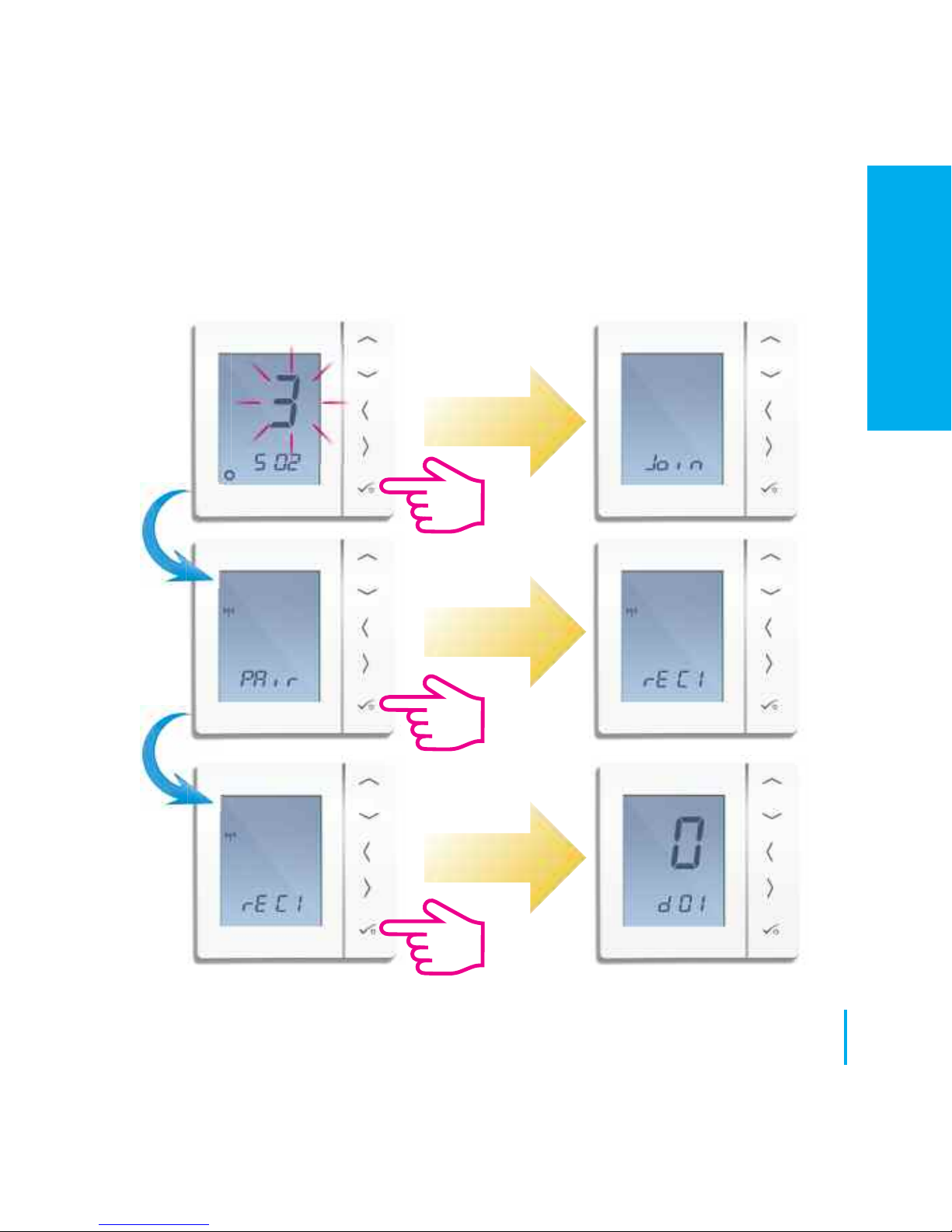
45
www.speedfitUFH.co.uk
Installation - Pairing with Boiler Receiver Only
INSTALLATION
Page 46
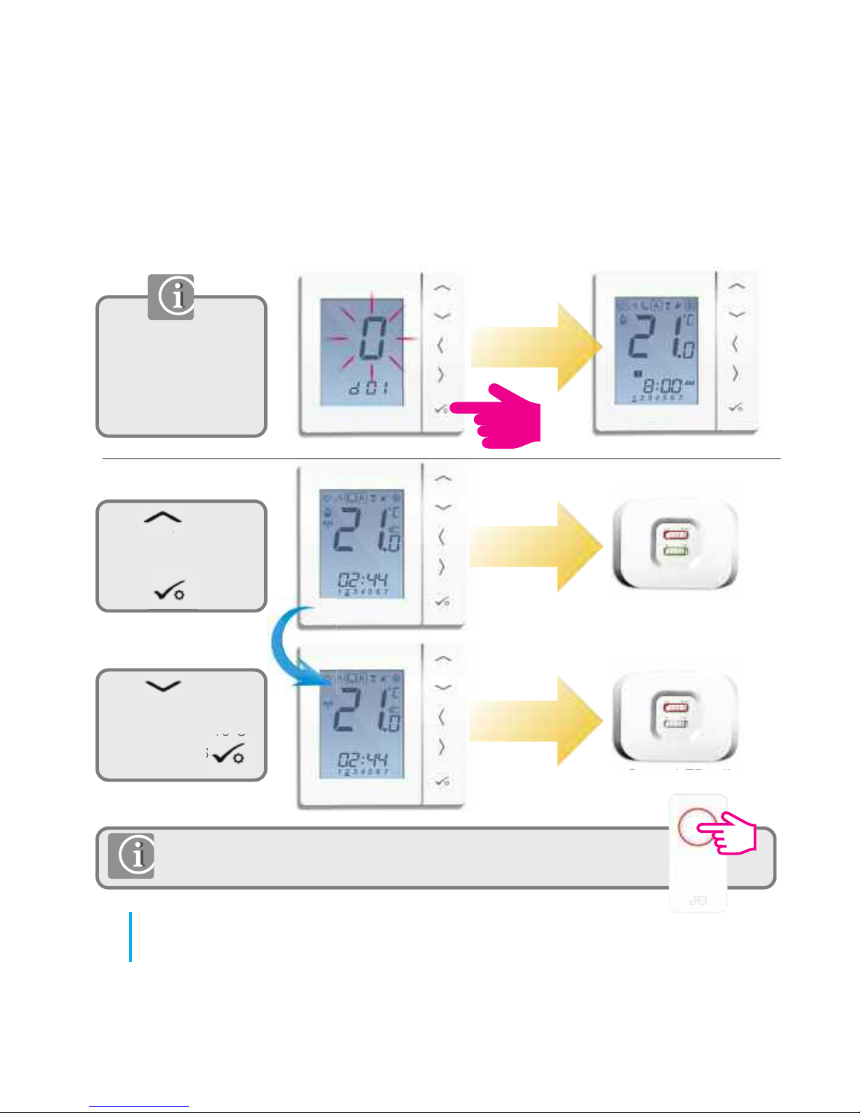
Long press to exit to
home screen or
continue to change
device settings.
Refer to page 57.
Use to
increase temperature
to 30ºC and then
press
Use to
decrease
temperature to 10ºC
and then press
Green LED on
Green LED off
If pairing for your system is complete, please take the coordinator
out of pair mode. Press for 5 seconds and light will stop flashing.
46
JGSTATW Instruction Manual
Installation - Pairing with Boiler Receiver Only
Page 47
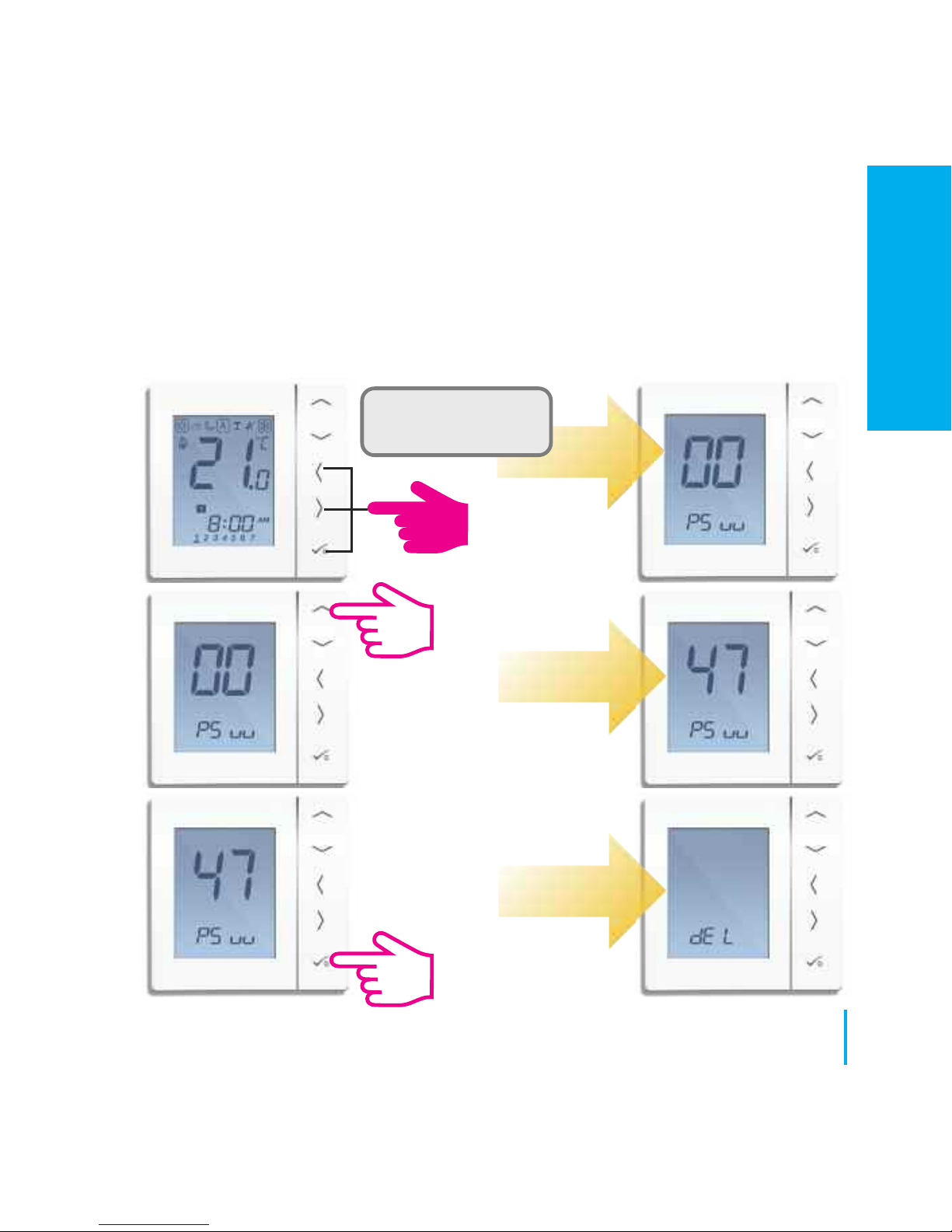
If you have made an error or need to change your system parameters please
follow steps below. This should only be done by your installer.
Press all three buttons
simultaneously
47
www.speedfitUFH.co.uk
Installation - Modifying System Parameters
INSTALLATION
Page 48
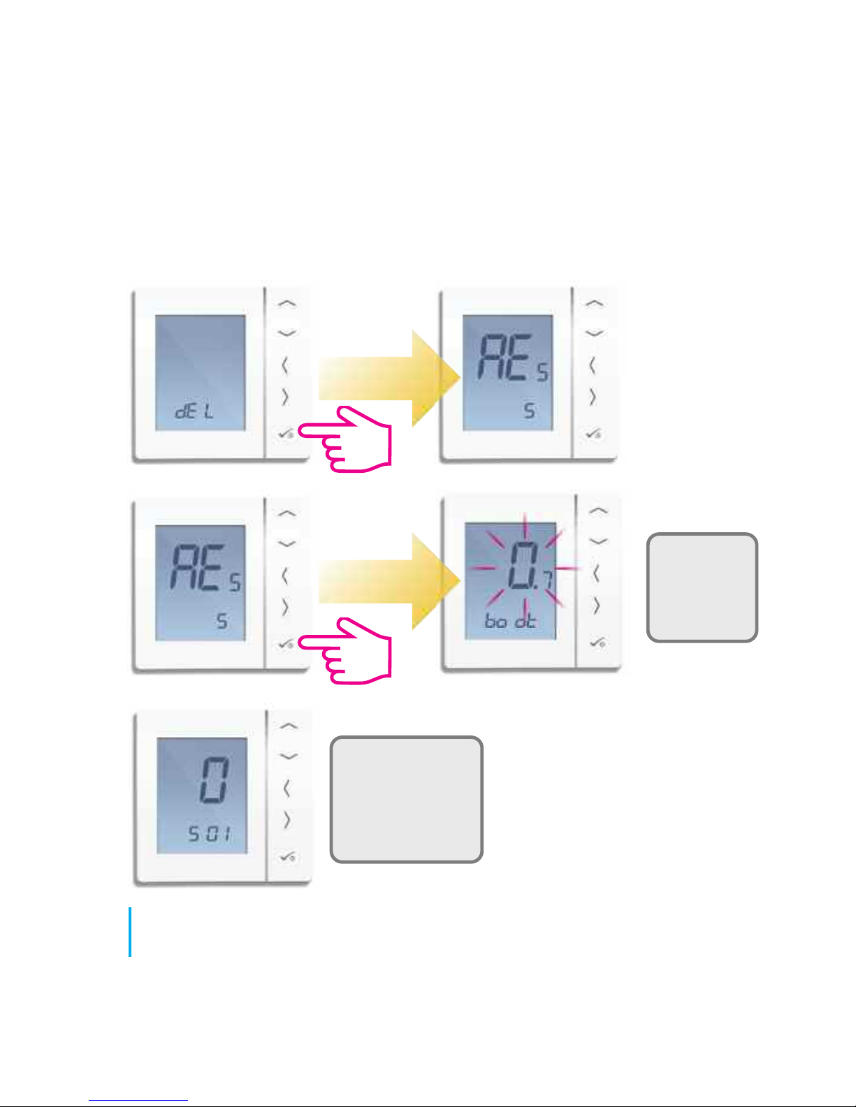
Unit will
follow power
up sequence
on page 29.
You are now ready
to enter or change
your System
Parameters.
Refer to page 31.
48
JGSTATW Instruction Manual
Installation - Modifying System Parameters
Page 49
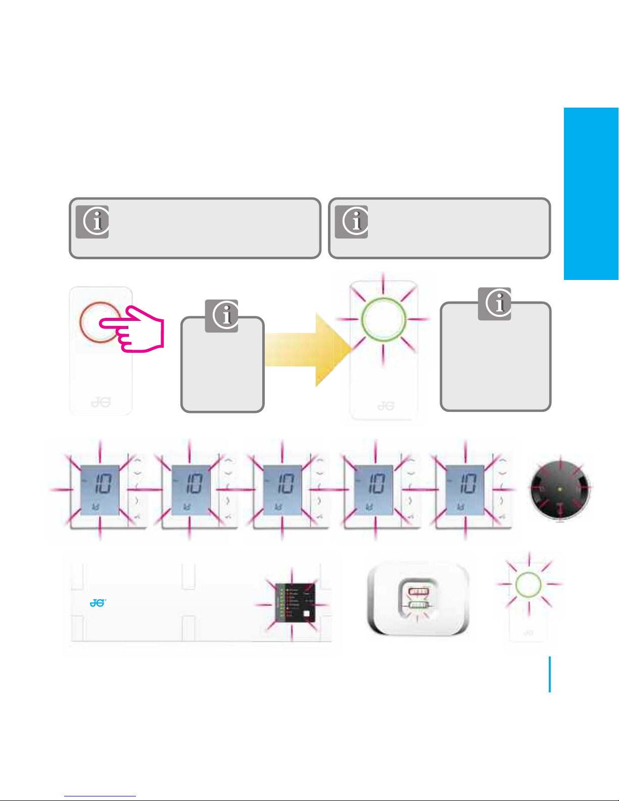
Press again for 1
second to cancel
identify. Identify
mode will time out
after 10 minutes.
To check that the complete system is
communicating and has been configured
correctly, you can use identify mode.
Using identify from the Coordinator
will show all products that are
connected to your system.
Press for 1
second to
activate
identify mode.
49
www.speedfitUFH.co.uk
Installation - Checking System Configuration
INSTALLATION
Page 50
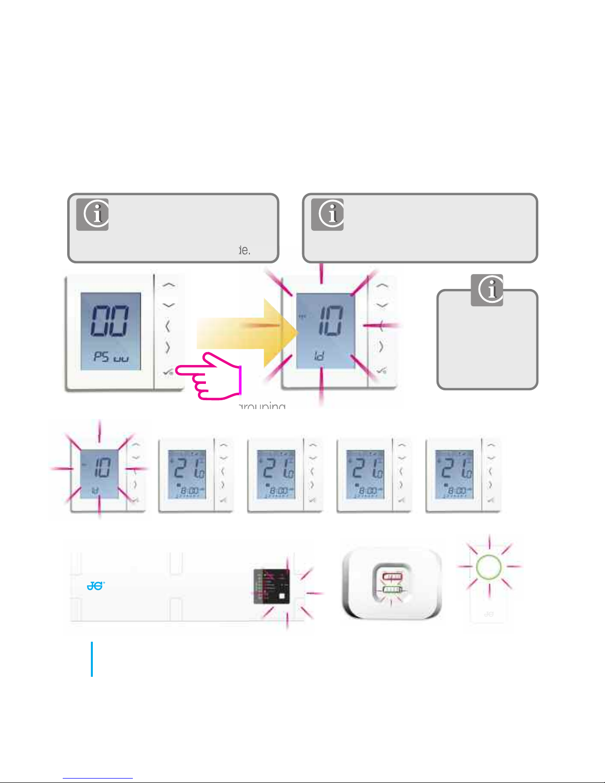
PRT
Press tick to
cancel identify.
Identify mode will
time out after 10
minutes.
System has no grouping
To check that the relevant
system is communicating and
has been configured correctly,
you can use identify mode.
PRT
PRT PRT PRT PRT
50
JGSTATW Instruction Manual
Installation - Checking System Configuration
Please follow step 1 on page 47.
When in identify mode all receivers
and the coordinator related to the
individual PRT will flash.
Page 51
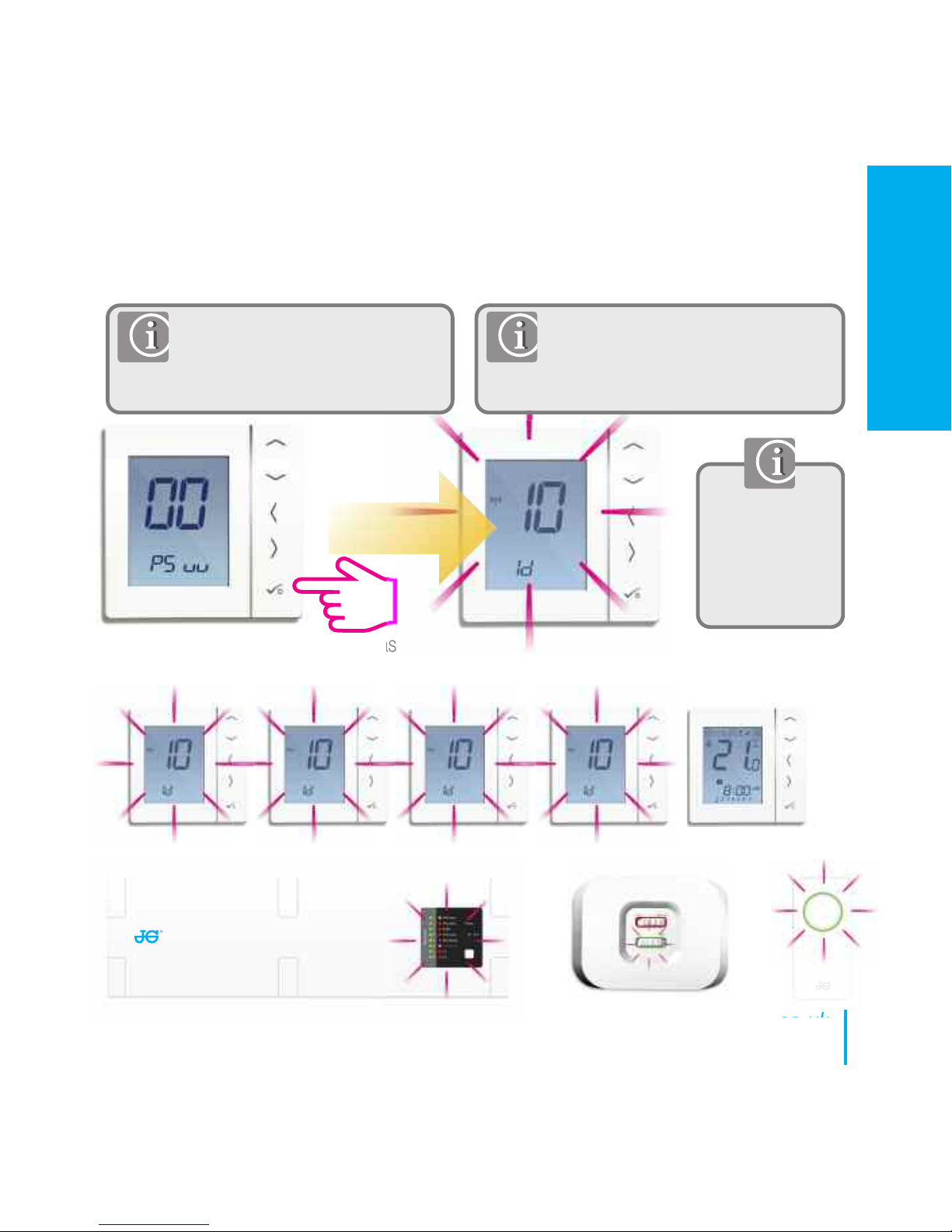
Group Control
Thermostat
System has
grouping
PRT
Group Control
Thermostat
Group
Thermostat
Group
Thermostat
Group
Thermostat
Press tick to
cancel identify.
Identify mode
will time out after
10 minutes.
To check that the relevant system
is communicating and has been
configured correctly, you can use
identify mode.
51
www.speedfitUFH.co.uk
Installation - Checking System Configuration
Please follow step 1 on page 47.
When in identify mode all receivers,
group thermostats and the
Coordinator will flash.
INSTALLATION
Page 52
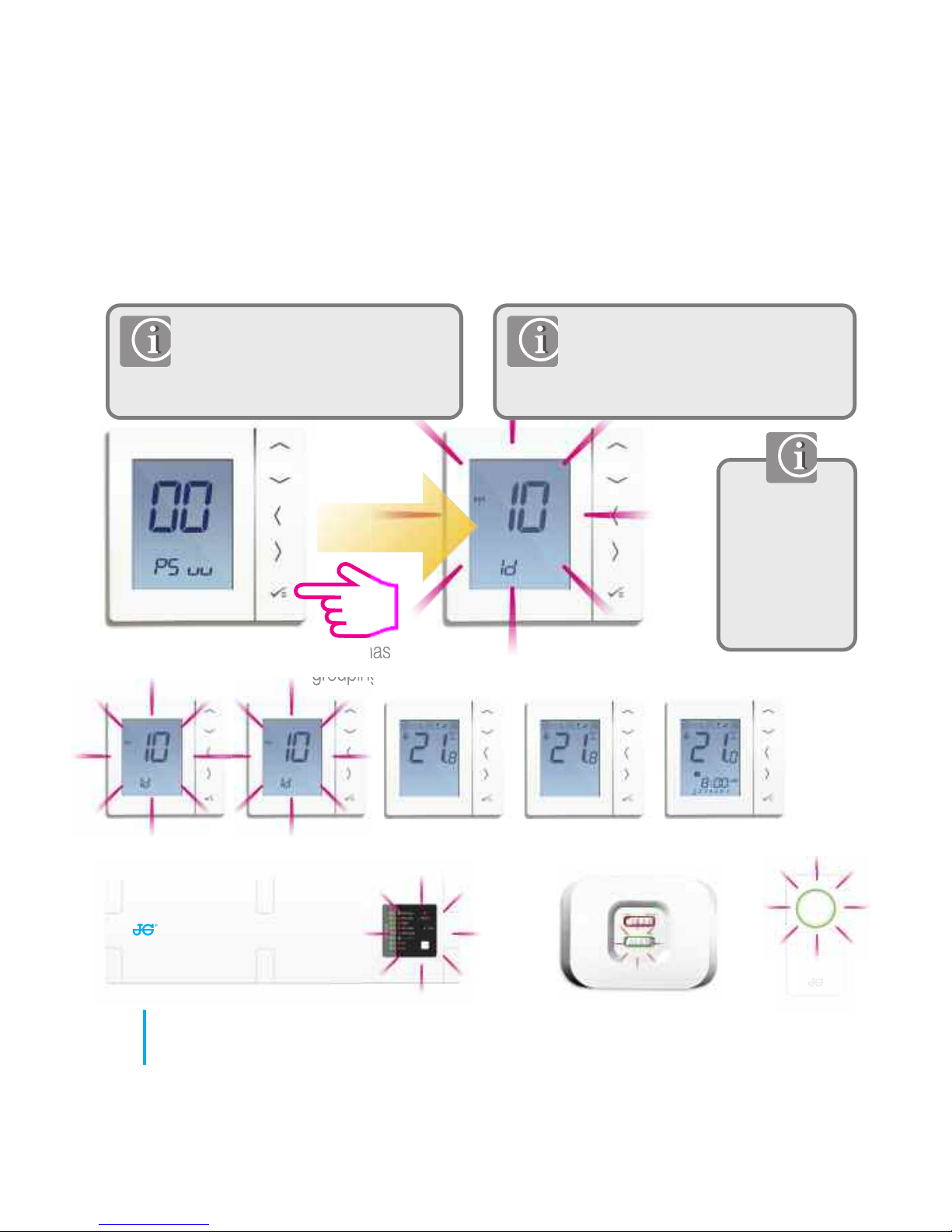
Group Thermostat
System has
grouping
PRTGroup Control
Thermostat
Group
Thermostat
Group
Thermostat
Group
Thermostat
Press tick to
cancel identify.
Identify mode
will time out
after 10
minutes.
To check that the relevant system
is communicating and has been
configured correctly, you can use
identify mode.
52
JGSTATW Instruction Manual
Installation - Checking System Configuration
Please follow step 1 on page 47.
When in identify mode all receivers,
control group thermostat and the
coordinator will flash.
Page 53
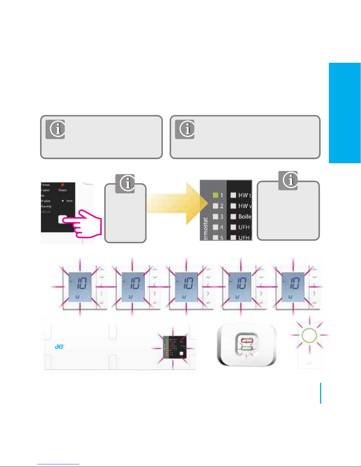
Press again for 1
second to cancel
identify. Identify
mode will time out
after 10 minutes.
To check that the complete
system is communicating and
has been configured correctly,
you can use identify mode.
Using identify from the wiring centre will
show all products that are connected to
your wiring centre. The wiring centre
number will also be shown.
Press for 5
second
to activate
identify
mode.
53
www.speedfitUFH.co.uk
Installation - Checking System Configuration
INSTALLATION
Page 54
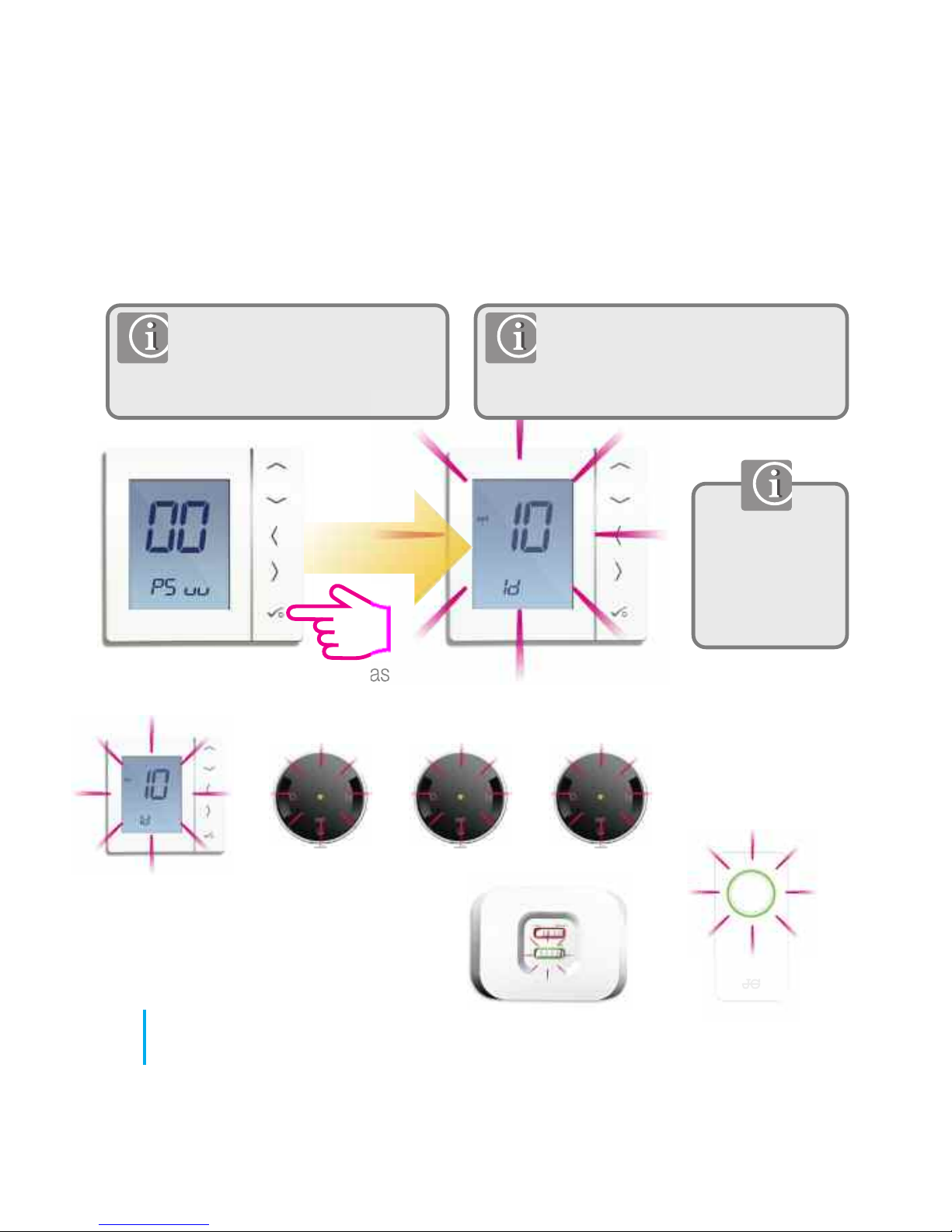
PRT
Press tick to
cancel identify.
Identify mode
will time out
after 10 minutes.
System has
no grouping
To check that the relevant system
is communicating and has been
configured correctly, you can use
identify mode.
TRV TRV TRV
54
JGSTATW Instruction Manual
Installation - Checking System Configuration
Please follow step 1 on page 47.
When in identify mode all radiator
valves, receivers and the coordinator
related to the individual PRT will flash.
PRT
Page 55
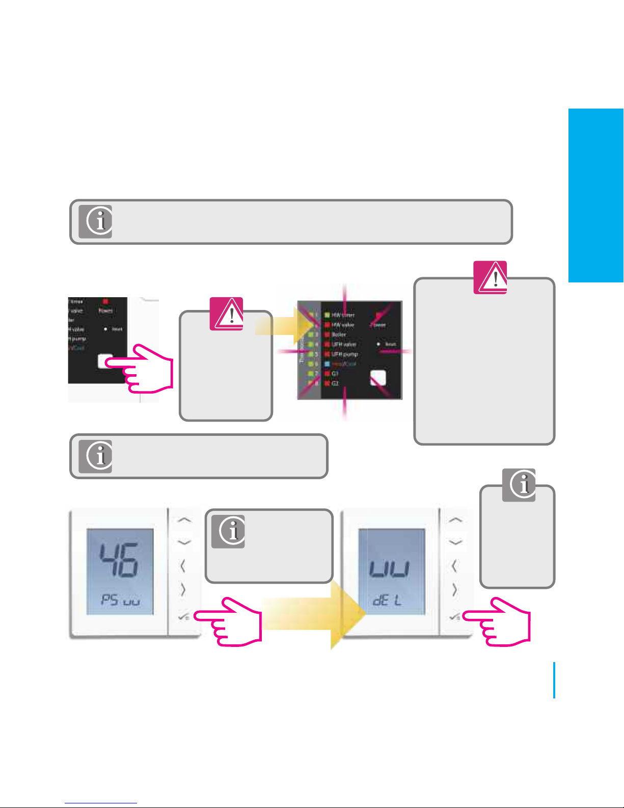
Deleting Wiring Centre from the network.
Press for 15
seconds to
delete the wiring
centre from the
network.
All LED’s will flash
momentarily and then the
wiring centre will be
deleted from the network.
All thermostats relating to
the wiring centre will
need to be reconfigured
and paired with the new
Wiring Centre.
If the wiring centre cannot be deleted
as above, use the method below.
Please follow
step 1 on page
47. Select
password 46.
You are now
ready to
install your
new wiring
centre.
Before replacing any device it must be removed from the Zigbee
network. Please ensure the Wireless Coordinator is also in pairing mode.
55
www.speedfitUFH.co.uk
Installation - Replacing Product
INSTALLATION
Page 56
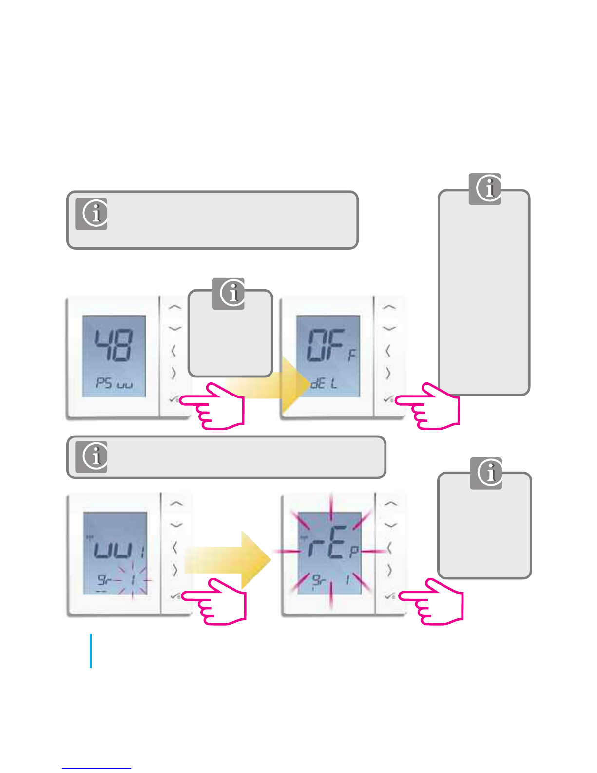
Before replacing any device it must be removed
from the Zigbee network. Please ensure the
Wireless Coordinator is also in pairing mode.
Note: If replacing a thermostat connected to the
wiring centre, you can use the replacement method.
Deleting thermostat from the network.
Your thermostat
will now be
deleted from the
network. You are
now ready to
install your new
thermostat. Please
note password 48
can also be used
to delete other
devices that are
offline.
Please follow
step 1 on page
47. Select
password 48.
The unit
previously
connected to
the wiring centre
will be replaced.
56
JGSTATW Instruction Manual
Installation - Replacing Product
Page 57
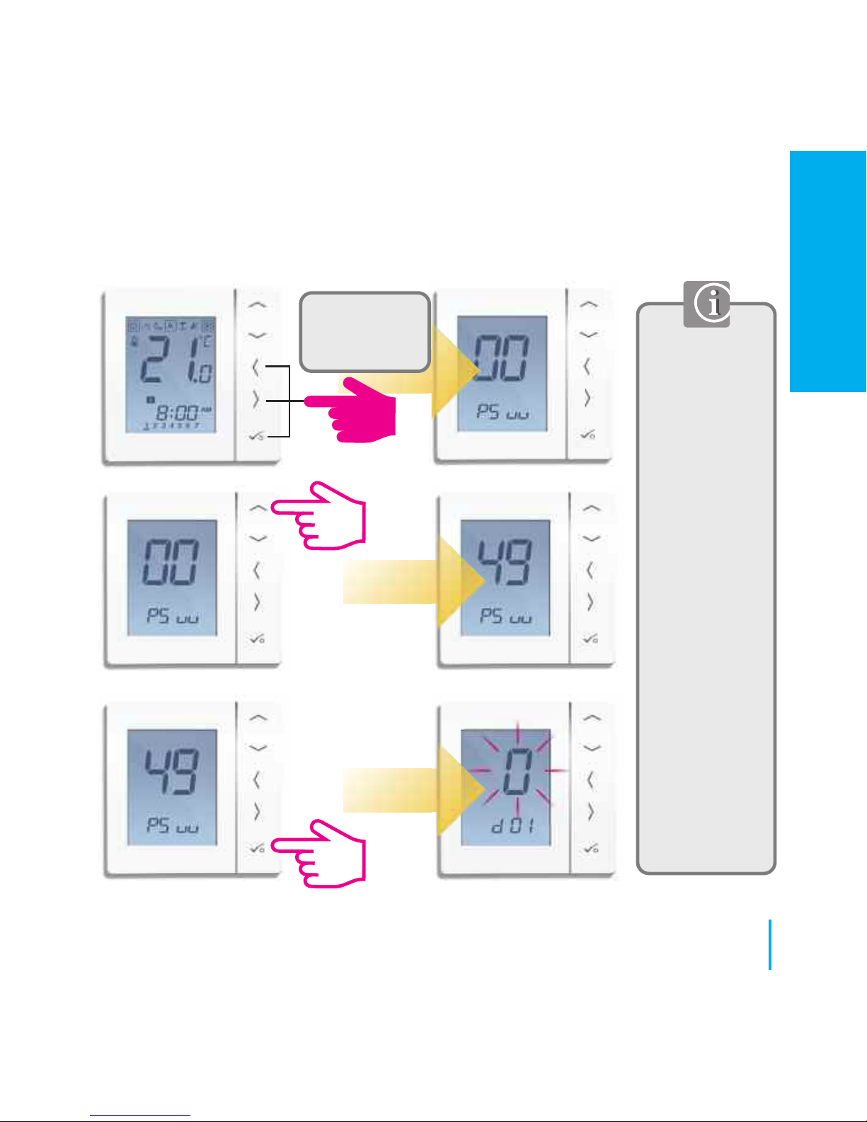
Device
parameters will
follow system
parameters on
first power up. If
you need to
change device
parameters
follow the steps
below.
Please note, your
system
parameters will
be shown first
but cannot be
edited in this
section. To
change the
system
parameters
please refer to
page 47.
Press all three
buttons
simultaneously
57
www.speedfitUFH.co.uk
Installation - Device Parameters
INSTALLATION
Page 58
58
JGSTATW Instruction Manual
Installation - Device Parameters
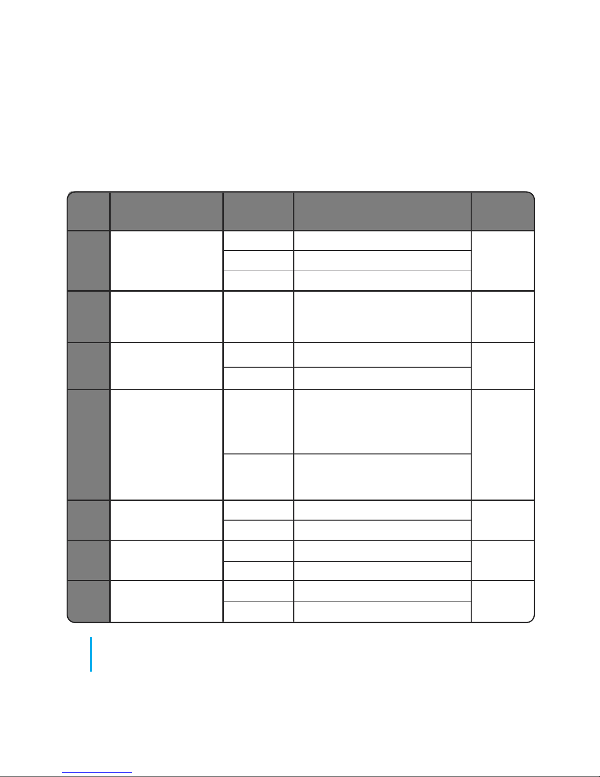
DX FUNCTION SYSTEM DEFINITION DEFAULT
SETTING
D01 Heating 0 Pulse Width Modulation
Control 1 On-Off 0.5ºC +/- 0.25ºC 0
2 On-Off 1.0ºC +/- 0.5ºC
D02 Room
-3.0 to
Temperature Offset from
Temperature
3.0ºC
Measured Temperature to 0ºC
Offset Compensate for any error
D03 Sensor probe or
0 Sensor/Cyl stat not Connected
Cylinder thermostat
1 Sensor/Cyl stat Connected
0
connection
D04 Sensor probe 0 D03 must be set to 1 then
used as air sensor external sensor be used as
or floor sensor Air sensor. There will be no
internal temp measurement
0
1 D03 must be set to 1 then external
sensor used for floor protection.
Internal temp is measured by stat
D05 Cooling Control 1 On-Off 0.5ºC +/- 0.25ºC
2
2 On-Off 1.0ºC +/- 0.5ºC
D06 Actuator type 0 NO Normally Open
1
1 NC Normally Closed
D07 Valve protection 0 Disable
1
1 Enable
Page 59
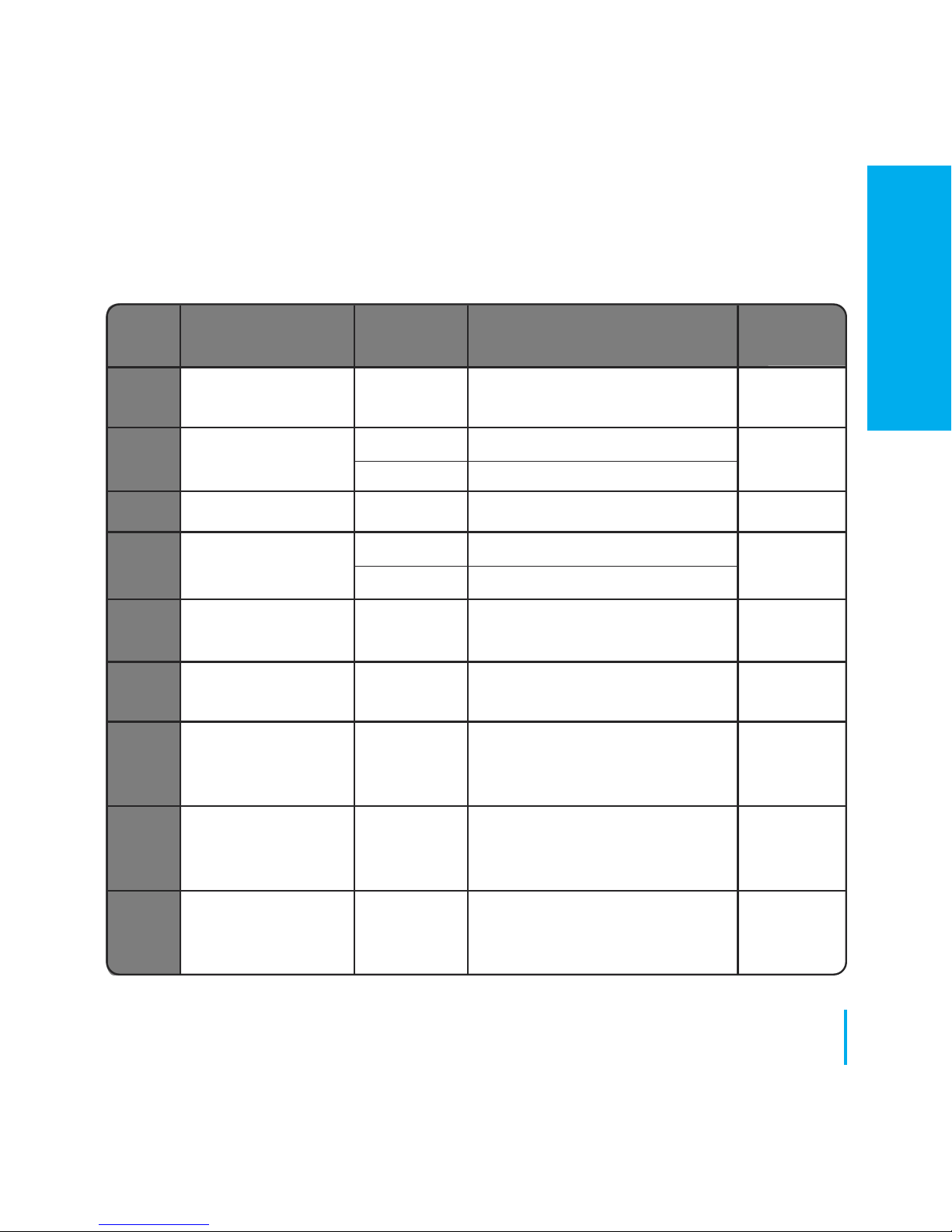
DX FUNCTION SYSTEM DEFINITION DEFAULT
SETTING
D08 Frost Set point 5ºC - 17ºC Required Temperature for frost 5ºC
Temperature protection and holiday mode
D09 Hour Format 0 12
1
1 24
D10 N/A N/A N/A N/A
D11 Daylight Saving 0 OFF
1
Time (DST) 1 ON
D12 Heating Set point
5ºC - 35ºC
Maximum temp that can
35ºC
Limit be set for heating
D13 Cooling Set point
5ºC - 40ºC
Maximum temp that can
5ºC
Limit be set for Cooling
D14 Floor sensor High Output relay will be switched off
Limit Temperature 6ºC -45ºC when temp is reached for 27ºC
floor protection
D15 Floor sensor Low Output relay will be switched on
Limit Temperature 6ºC - 45ºC when temp is reached for 10ºC
floor protection
D16 Floor sensor Limit Output relay will be switched off
for cooling 6ºC -45ºC when temp is reached for 6ºC
floor protection
59
www.speedfitUFH.co.uk
Installation - Device Parameters continued
INSTALLATION
Page 60
60
JGSTATW Instruction Manual
Installation - Error Codes
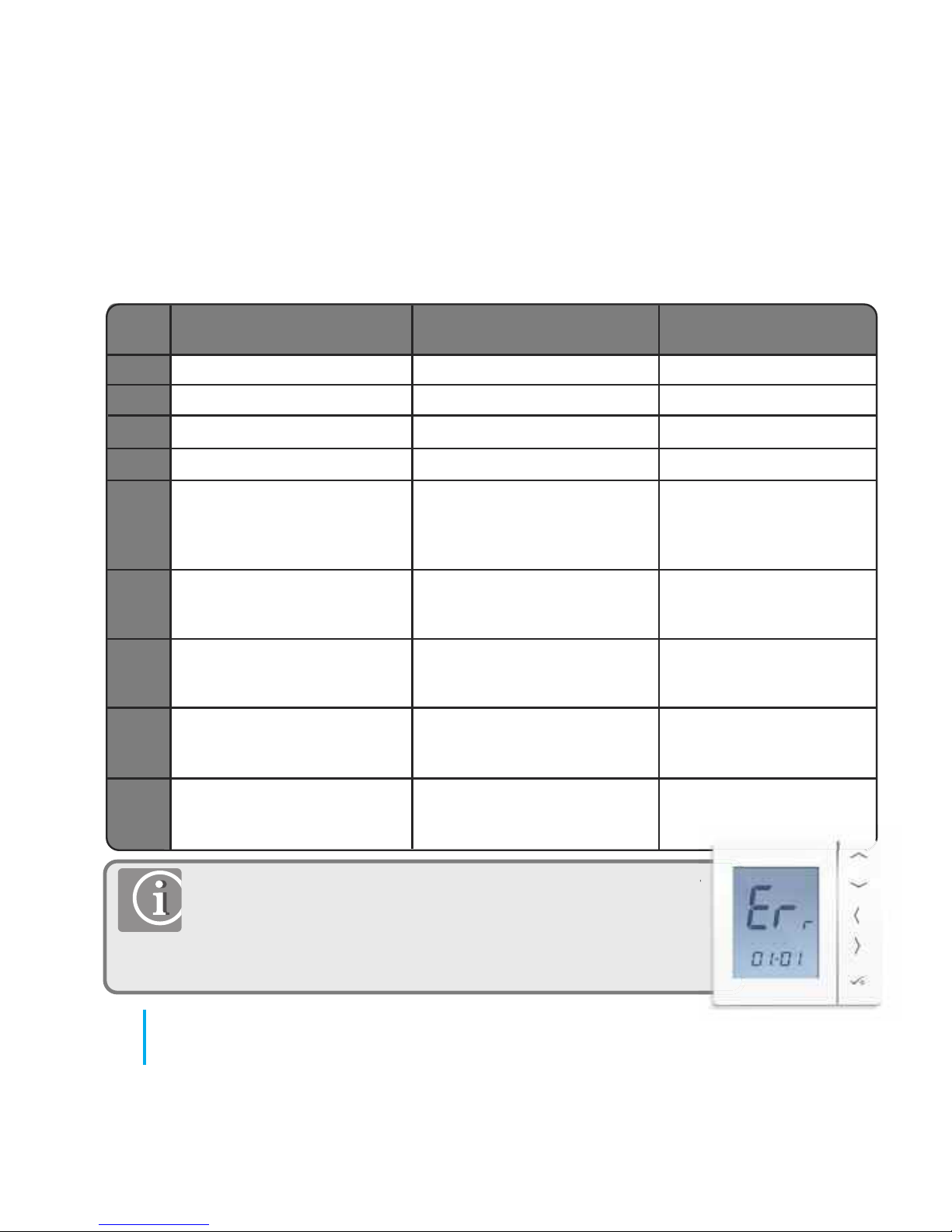
Error Prog Non-Prog HW
Code
01
02
03
04
05
06
07
08
09
Comm Connection link failure
Comm Connection link failure
Prog/Non-prog/HW thermostat
lost link with Coordinator
(Displayed on related Thermostat)
Comm Connection link failure
Prog/Non-prog/HW thermostat
lost link with Coordinator
(Displayed on related Thermostat)
Comm Connection link failure
Prog/Non-prog/HW thermostat
lost link with WC (Displayed on
related Thermostat)
Prog/Non-prog Thermostat lost
link with TRV (Displayed on
related Thermostat)
Prog/Non-prog Thermostat lost
link with Receiver RX 2
(Displayed on related Thermostat)
Comm Connection link failure
Comm Connection link failure
Prog/Non-prog/HW thermostat
lost link with WC (Displayed on
related Thermostat)
Prog/Non-prog Thermostat lost
link with TRV (Displayed on
related Thermostat)
Prog/Non-prog Thermostat lost
link with Receiver RX 2 (Displayed
on related Thermostat)
Comm Connection link failure
Comm Connection link failure
Floor sensor open Floor sensor open
-
Floor sensor short Floor sensor short
-
HW lost link with Coordinator
HW lost link with WC
-
Prog/Non-prog Thermostat lost
link with Receiver RX 1 (Displayed
on related Thermostat)
Prog/Non-prog Thermostat lost
link with Receiver RX 1 (Displayed
on related Thermostat)
-
-
If there is more than 1 error, then on Error page, press UP to show other error codes.
e.g. Err 03 05 ===> 3 errors Error code 05 ( 1st one )
Press Up to show Err 03 08 ===> 3 errors Error code 08 ( 2nd one )
Press Up again to show Err 03 09 ===> 3 errors Error code 09 ( 3rd one )
Press Up again to show Err 03 05 again......
Press OK to exit Error page back to Home display.
Page 61
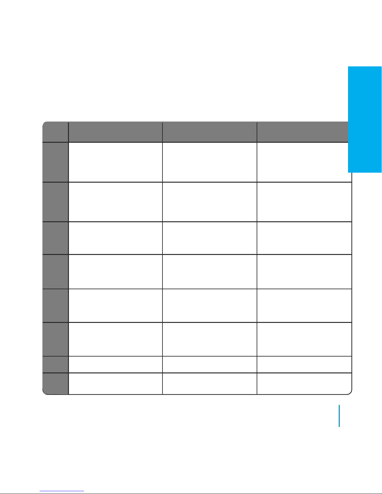
Error Prog Non-Prog HW
Code
10
11-18
19
20
21
22
23
24
61
www.speedfitUFH.co.uk
Installation - Error Codes
WC lost link with hot water timer
(Displayed on all relevant
thermostats and also hot water
timer)
WC lost link with zone
11=Zone 1, 12=Zone 2 etc
Displayed on all
connected thermostats
WC lost link with coordinator
(Displayed on all connected
thermostats and hot water timer)
WC lost link with receiver RX1
(Displayed on all connected
thermostats and hot water timer)
TRV lost link with coordinator
(Displayed on all connected
thermostats)
TRV low battery
(Displayed on all connected
thermostats)
Invalid TRV
Unit is rejected by wiring centre
Comm Connection link failure
(Displayed on all relevant
thermostats and also hot water
timer)
Comm Connection link failure
11=Zone 1, 12=Zone 2 etc
Displayed on all connected
thermostats
WC lost link with coordinator
(Displayed on all connected
thermostats and hot water timer)
WC lost link with receiver RX1
(Displayed on all connected
thermostats and hot water timer)
TRV lost link with coordinator
(Displayed on all connected
thermostats)
TRV low battery
(Displayed on all connected
thermostats)
Invalid TRV
Unit is rejected by wiring centre
Comm Connection link failure
(Displayed on all relevant
thermostats and also hot water
timer)
-
WC lost link with coordinator
(Displayed on all connected
thermostats and hot water timer)
WC lost link with receiver RX1
(Displayed on all connected
thermostats and hot water timer)
-
-
-
-
INSTALLATION
Page 62
62
JGSTATW Instruction Manual
Installation - Technical Detail
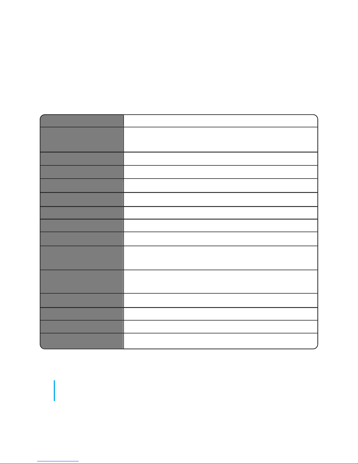
Model JGSTATW1 / JGSTATW2
Type Wireless Electronic programmable room thermostat (PRT),
digital room thermostat and Hot Water Timer
Programming Modes User selectable for 5/2, ALL and Individual day options
Program Number 1 - 6 Selectable
Modes Party, Holiday, Program and Frost
Override Permanent and temporary
Frost Protection 5ºC Adjustable
Power Source 230v AC 50Hz JGSTATW2 - 4 x AAA JGSTATW1
Temperature Scale 5ºC to 35ºC, tolerance 0.5ºC
Heat/Cool Global changeover using communication bus and external
input to the wiring centre
Sensor Air or floor protection. Cylinder thermostat when configured
for hot water timer.
Device Parameters See pages 58 - 59 for full list of functions
Operating Temperature 0 to 50ºC
Storage Temperature -20 to 60ºC
Frequency 2.4HGz Zigbee
Page 63
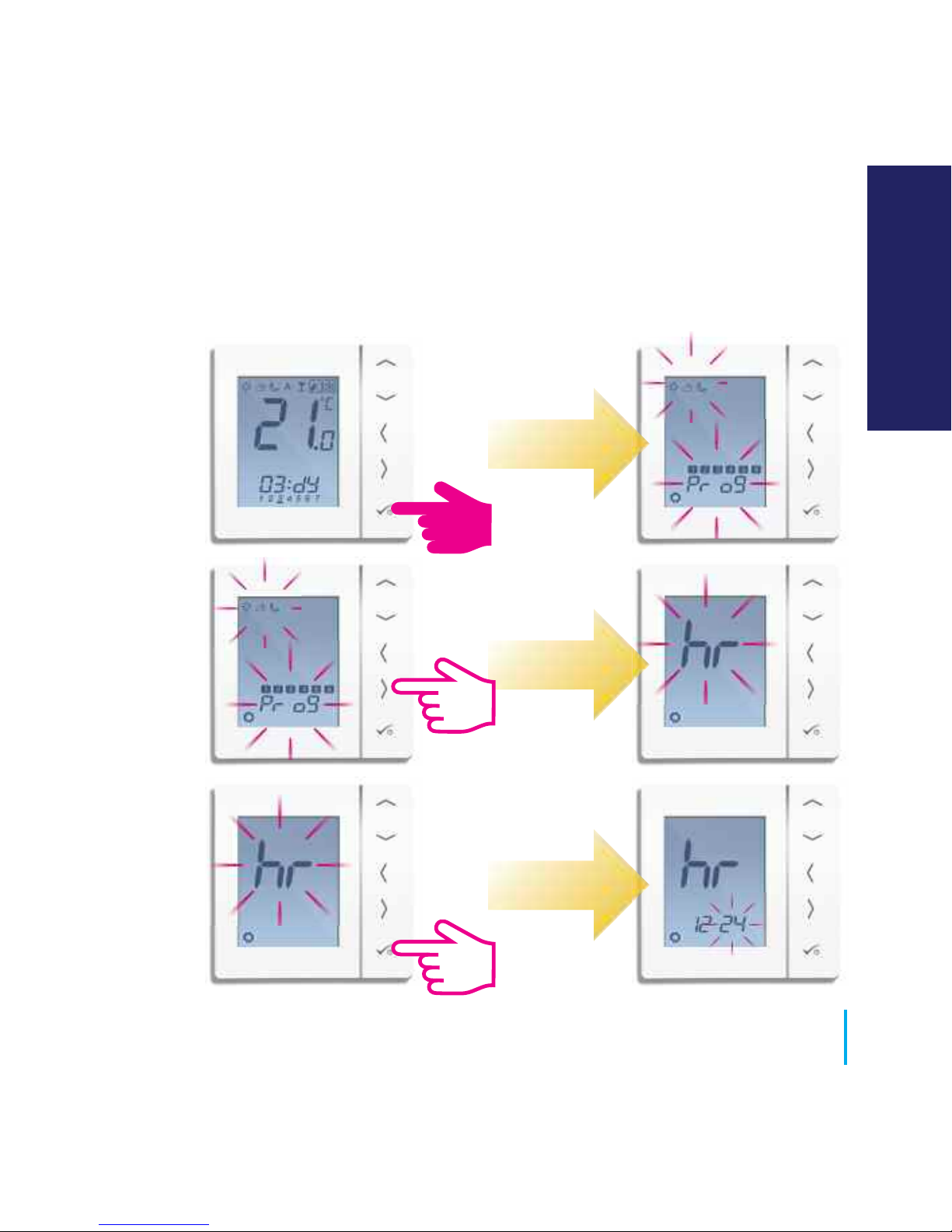
PRT and Group Control Thermostat.
63
www.speedfitUFH.co.uk
User Guide - Setting Time and Date
USER GUIDE
Page 64
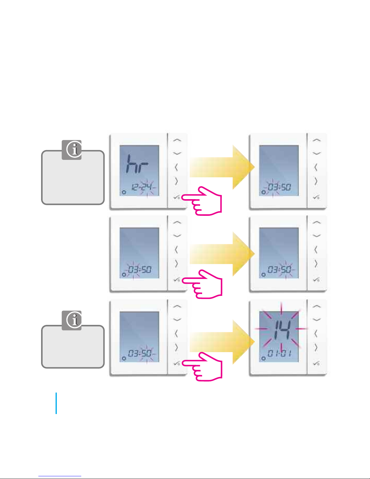
Use Left to
select 12 hour
and right to
select 24 hour.
Adjust the time
using the up or
down arrow key.
PRT and Group Control Thermostat.
Hour
Minutes
64
JGSTATW Instruction Manual
User Guide - Setting time and date
Page 65
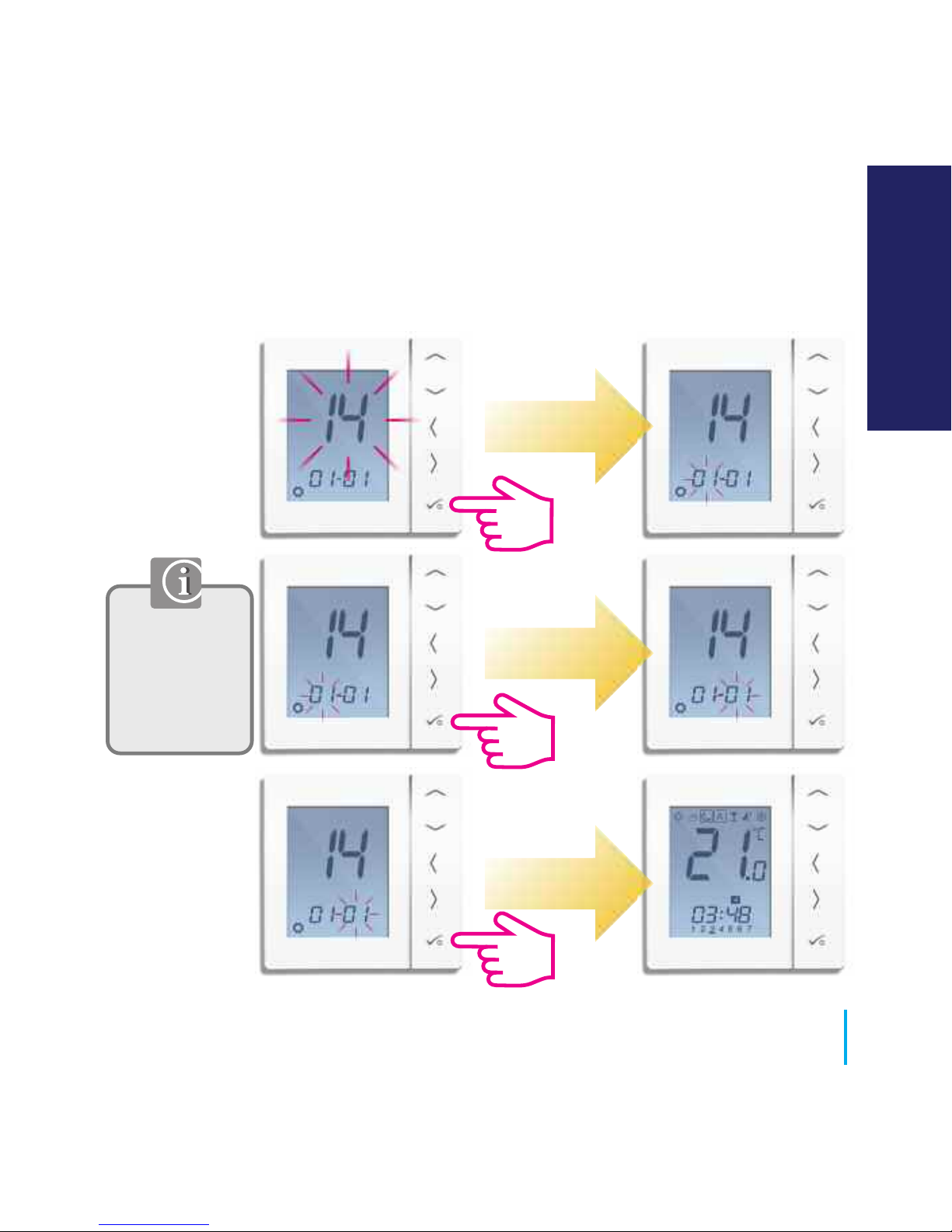
PRT and Group Control Thermostat.
Month
Year
Day
Adjust the
year/month/day
using the up or
down arrow
key.
65
www.speedfitUFH.co.uk
User Guide - Setting time and date
USER GUIDE
Page 66
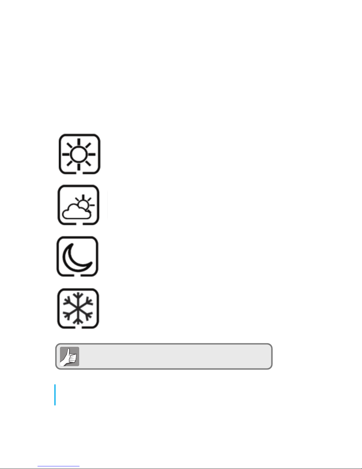
Highest Temperature typically used for
early morning and early evening.
Typically 21ºC
Mid Temperature typically used for times of
day when you are active around the home
Typically 19ºC
Lower Temperature typically used for
unoccupied or sleep times.
Typically 17ºC for UFH or 15ºC for radiators
Frost Temperature typically used for
Periods of long absence or
holidays.
Typically 5ºC
Your thermostat comes preset for the above temperatures.
These can be adjusted please see page 71
PRT, Group Control Thermostat and Group Thermostat
66
JGSTATW Instruction Manual
User Guide - Understanding Temperature Levels Heating
Page 67
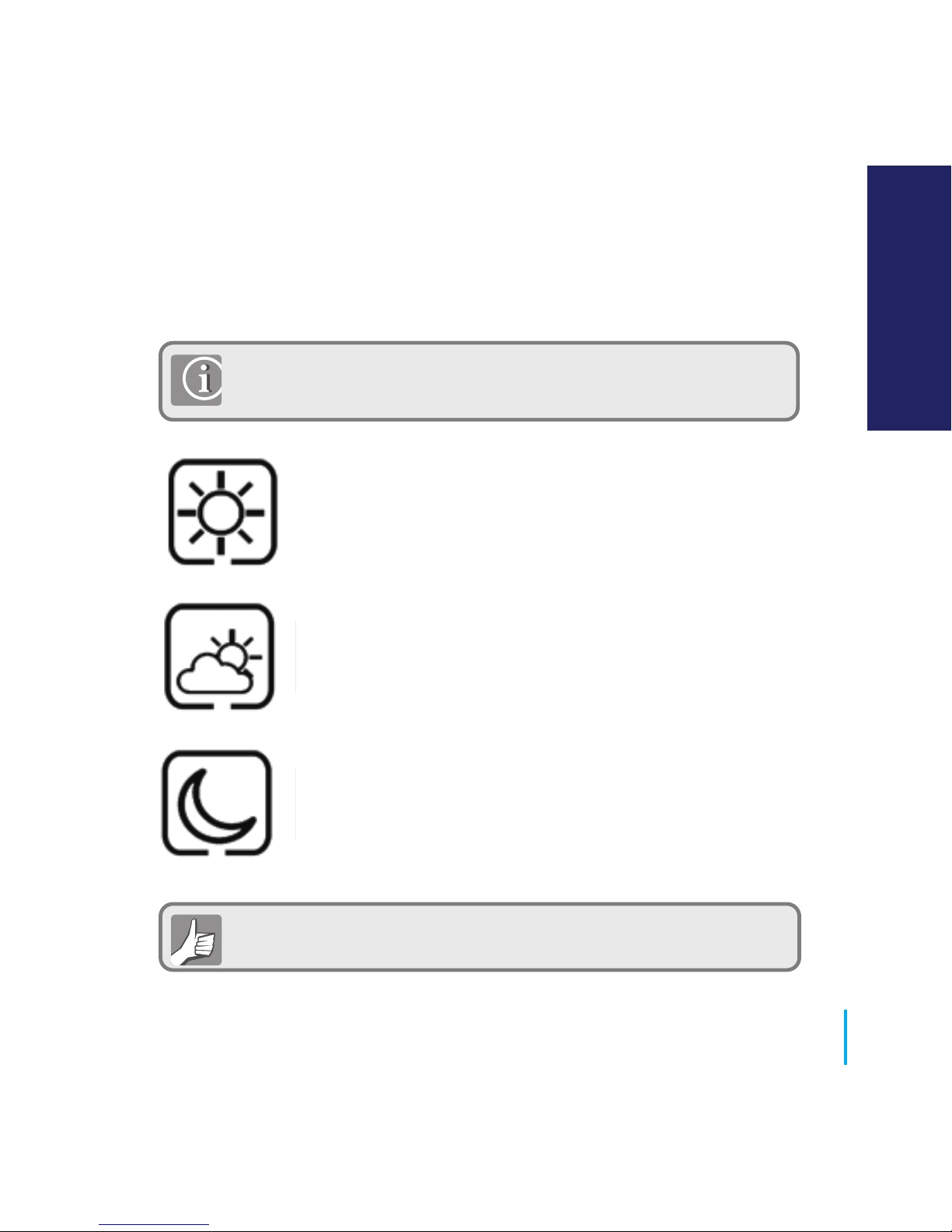
Occupied temperature typically 22ºC.
Unoccupied temperature typically 40ºC
This avoids cooling being active when the property is
unoccupied.
Evening temperature typically 24ºC.
Your thermostat comes preset for the above temperatures. These can
be adjusted (please see page 71).
Cooling is only available if your system supports this and the relevant
configurations and connections have been made to the unit.
PRT, Group Control Thermostat and Group Thermostat
67
www.speedfitUFH.co.uk
User Guide - Understanding Temperature Levels Cooling
USER GUIDE
Page 68
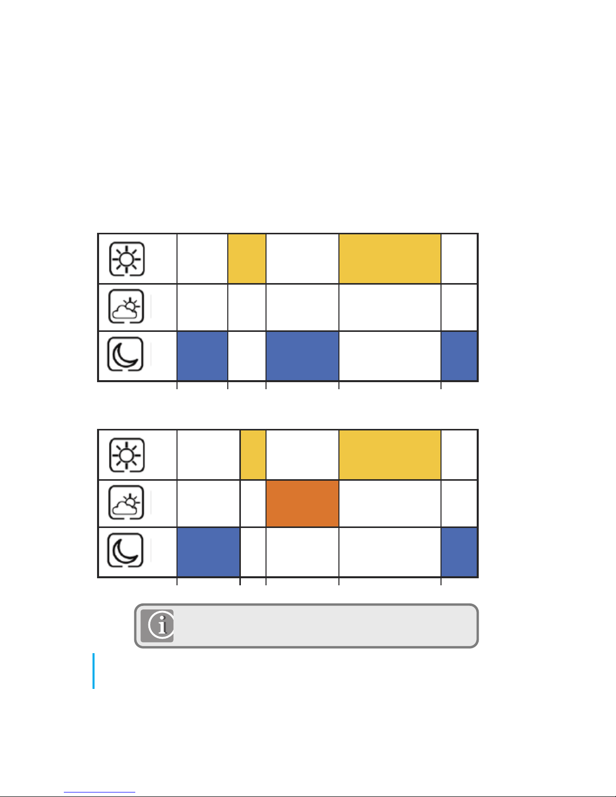
12.00 7.00 9.00 17.00 23.00
Monday to Friday
12.00 8.00 9.00 17.00 23.00
Saturday to Sunday
PRT and Group Control Thermostat
If using grouping, the schedule from the Group Control
Thermostat will be applied to group members.
68
JGSTATW Instruction Manual
User Guide - Default Heating Schedule
21
19
17
21
19
17
Page 69
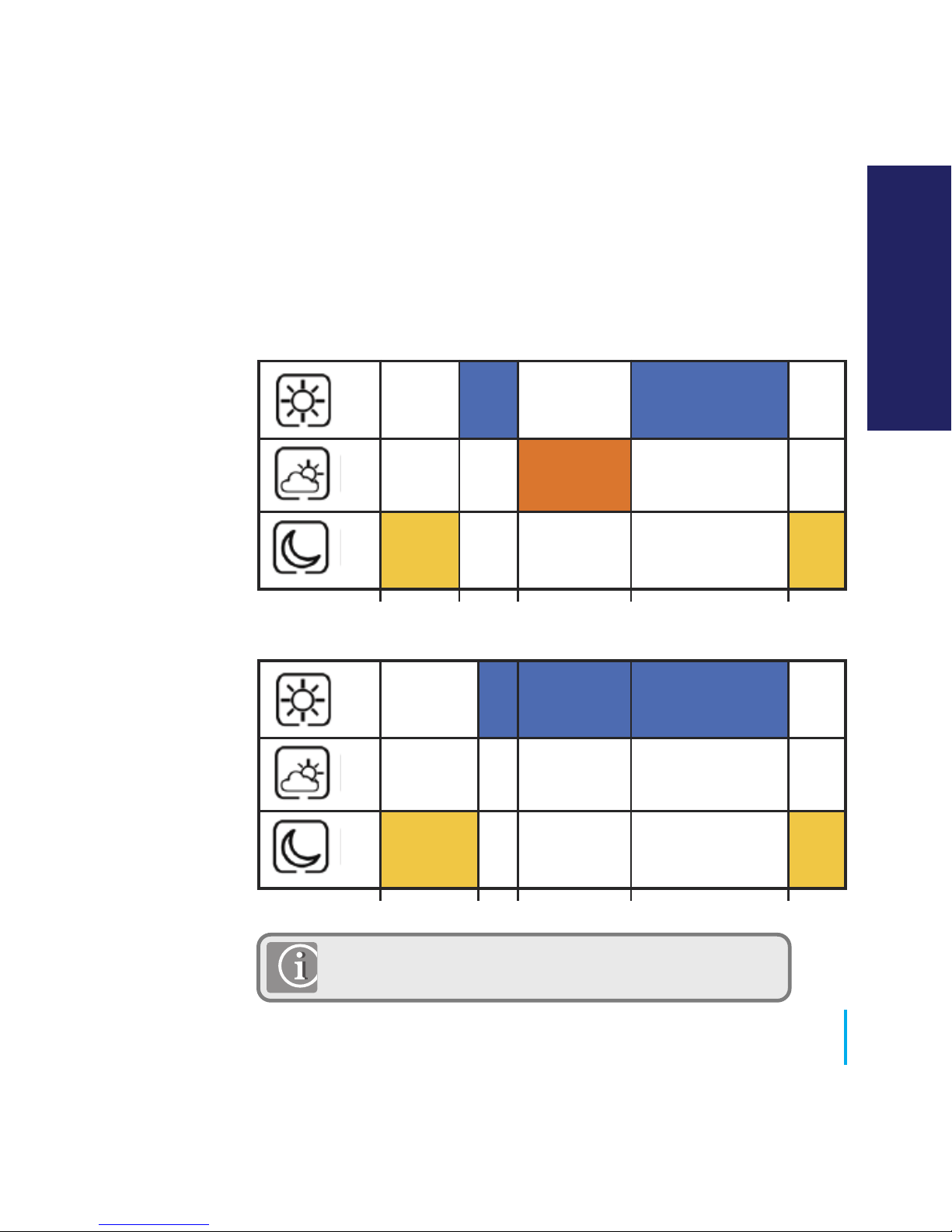
22
40
24
12.00
7.00
9.00 17.00 23.00
Monday to Friday
12.00 8.00 9.00 17.00 23.00
Saturday to Sunday
PRT and Group Control Thermostat
If using grouping, the schedule from the group control
thermostat will be applied to group members.
69
www.speedfitUFH.co.uk
User Guide - Default Cooling Schedule
22
40
24
USER GUIDE
Page 70
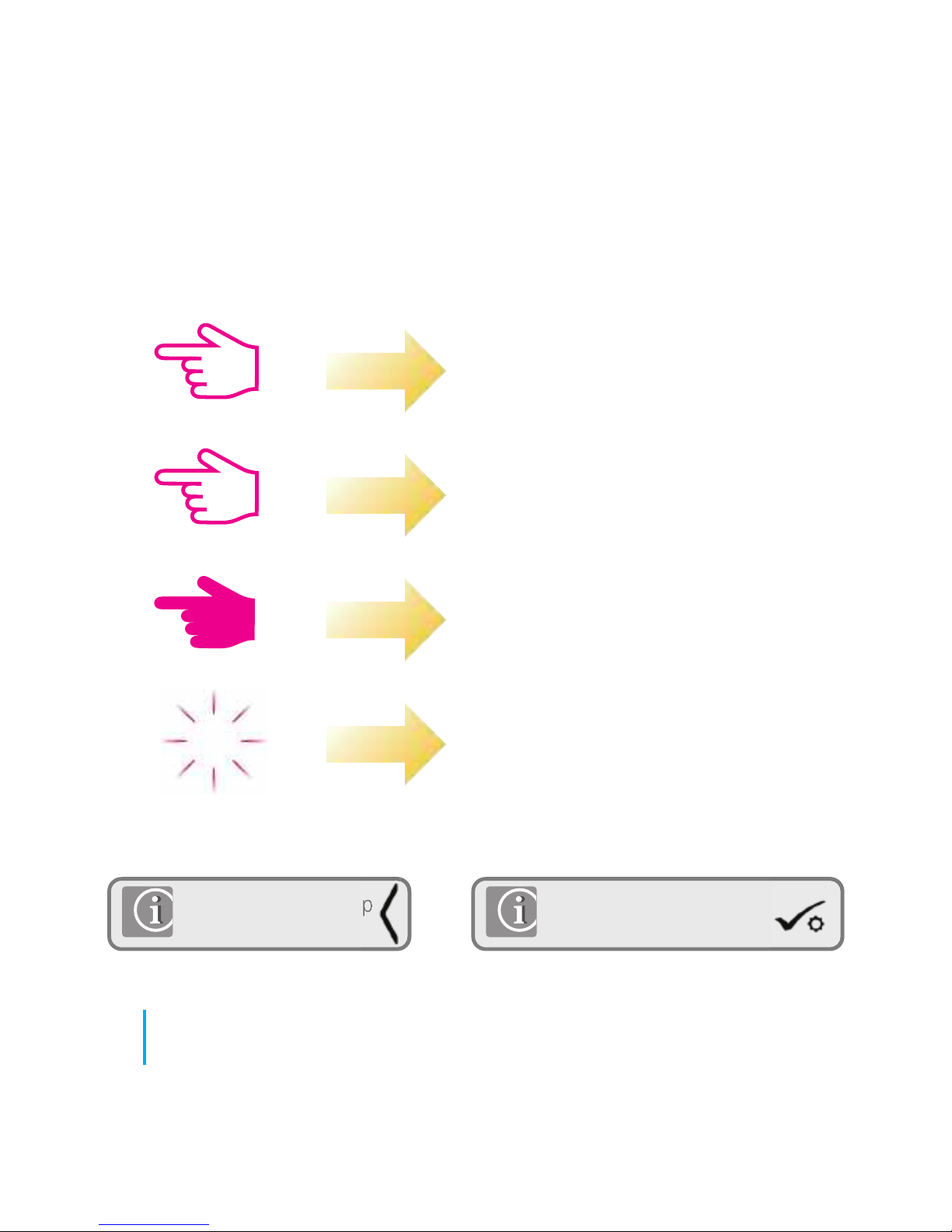
Press once
Press x amount of times
Hold for five seconds
Flashing
xx
Short press to save and
long press to save and exit
Short press to back up
70
JGSTATW Instruction Manual
User Guide - Graphics Key
Page 71
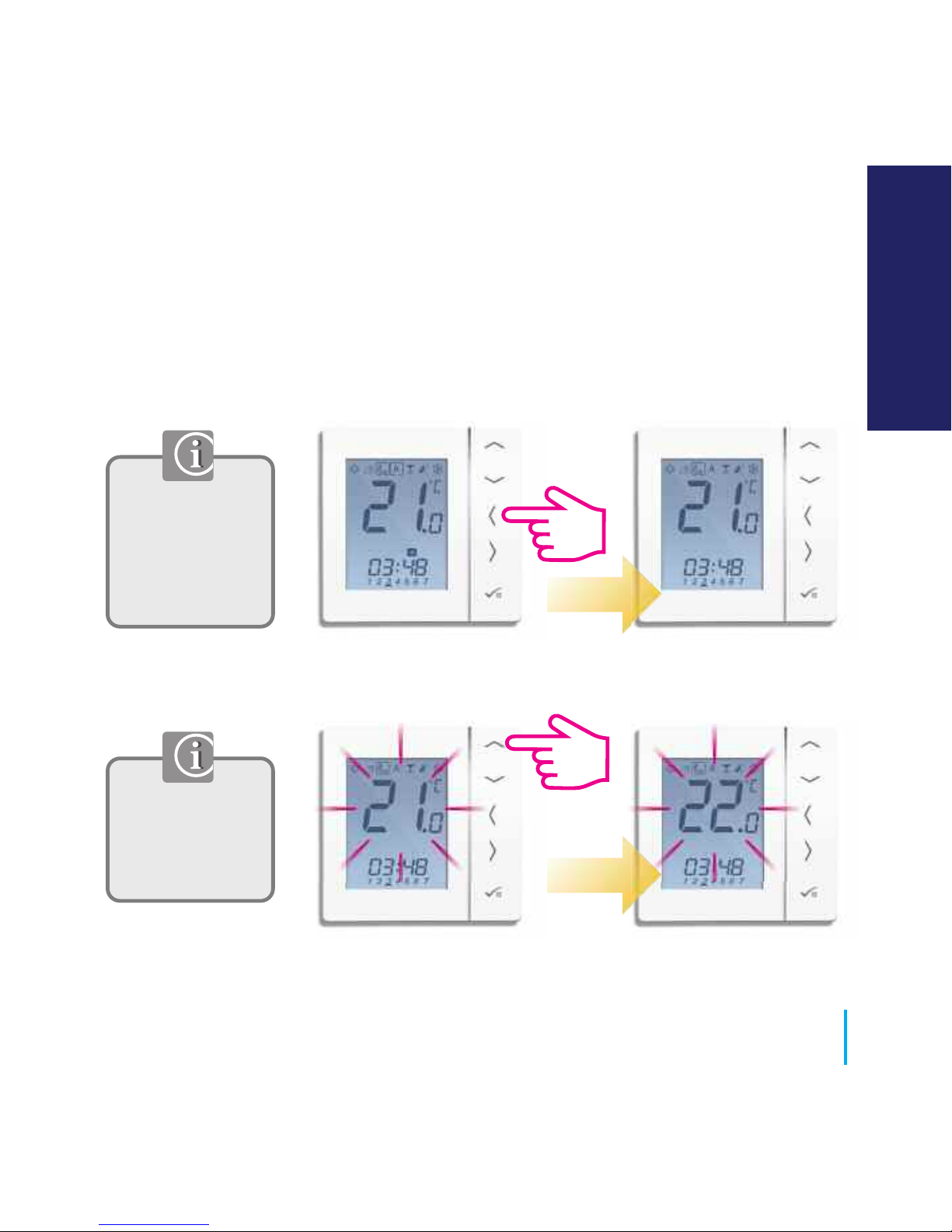
By setting the low
temperature the
program schedule
will use this as the
low setting.
The temperature
set are applicable
to the individual
thermostat.
PRT, Group Control Thermostat and Group Thermostat.
Setting the low temperature.
71
www.speedfitUFH.co.uk
User Guide - Setting Required Temperature Levels
USER GUIDE
Page 72
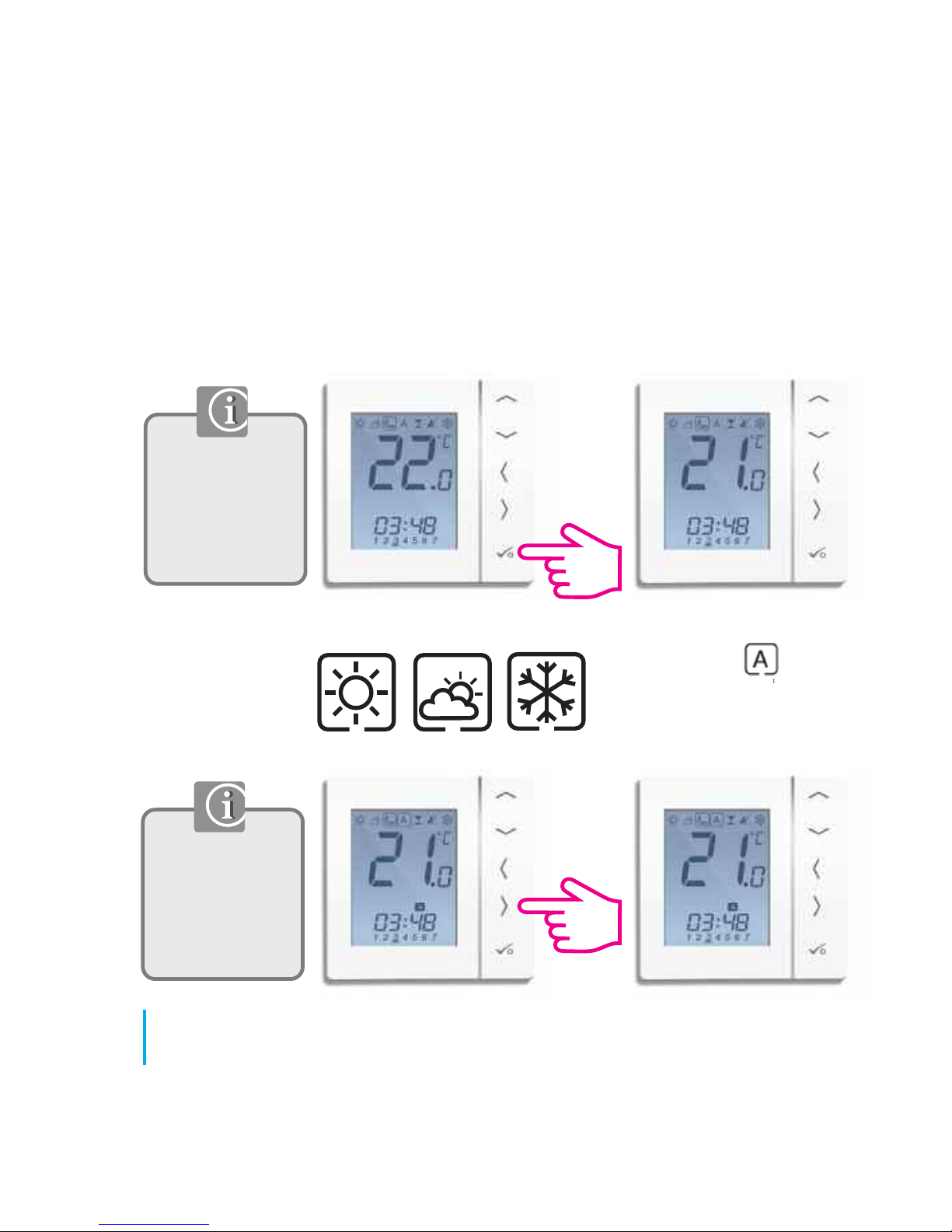
Repeat for
Move back to
once temperature levels
have been chosen.
By setting the
low temperature
the programs will
use this as the
low setting.
The temperature
set are
applicable to the
individual
thermostat.
PRT, Group Control Thermostat and Group Thermostat.
72
JGSTATW Instruction Manual
User Guide - Setting Required Temperature Levels
Page 73
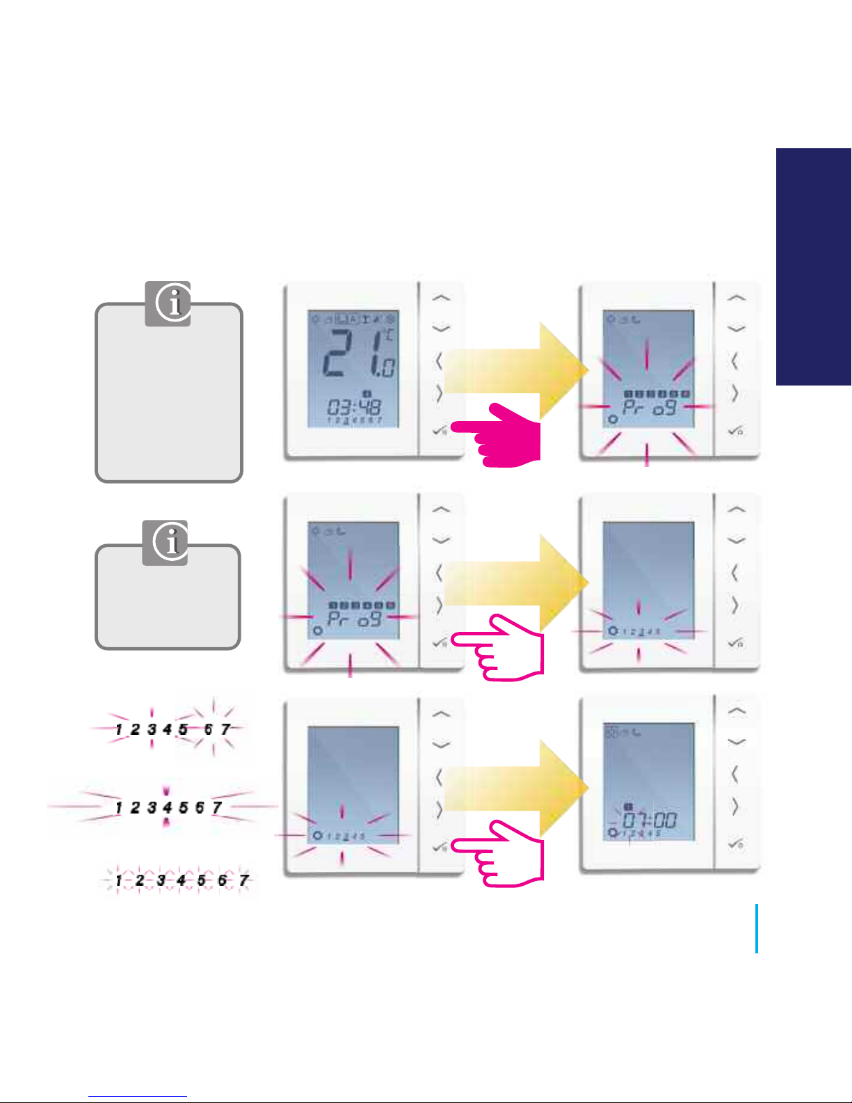
Use right and left
to select the day
of the programs.
5/2
7 Days
Individual
If using grouping,
the schedule from
the group control
thermostat will be
applied to group
members.
73
www.speedfitUFH.co.uk
User Guide - Setting the Temperature Schedule
USER GUIDE
Page 74
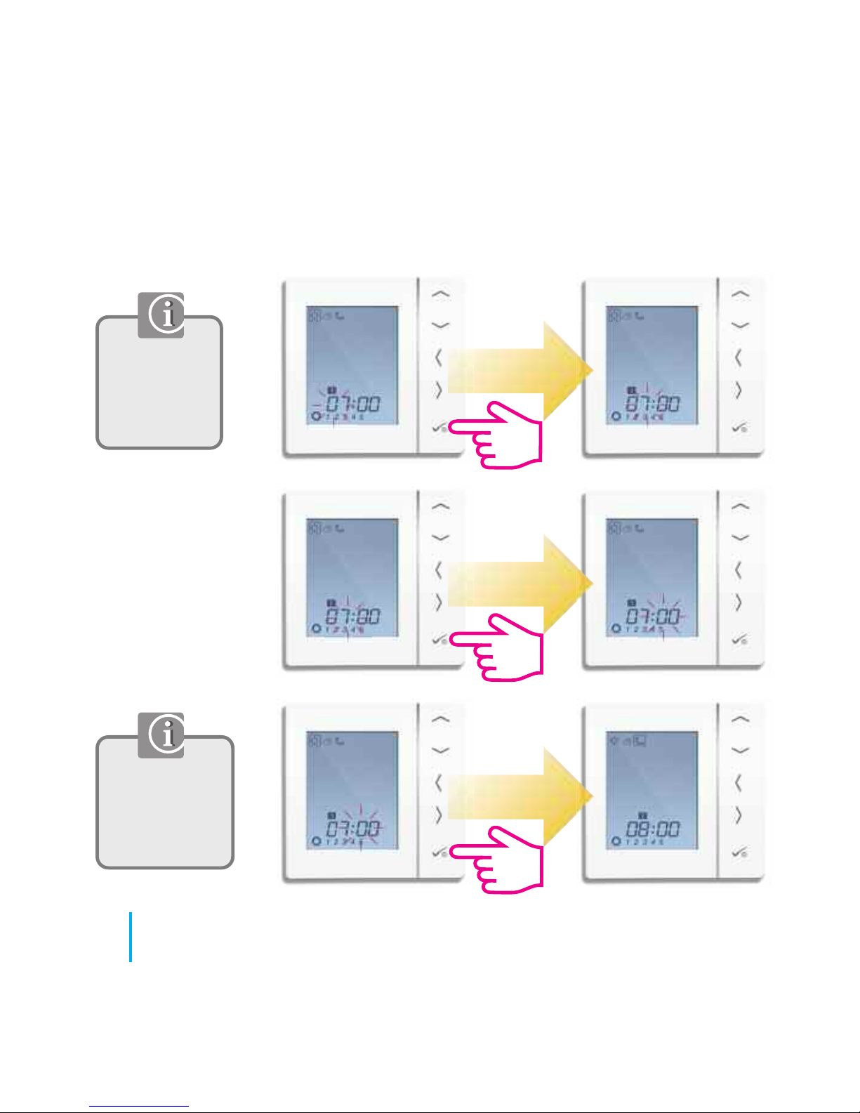
Adjust the
time using the
up or down
arrow key.
Use right and
left to select
the Hi/Mid or
low temp.
74
JGSTATW Instruction Manual
User Guide - Setting the Temperature Schedule
Page 75
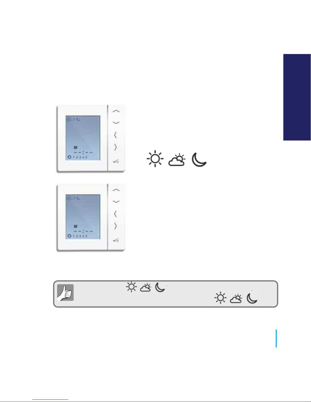
When you set the temperature the schedule will respond to
those temperatures see page 71 on how to change
Repeat through to program 4.
If you require a 5th or 6th program enter
a time and select your temperature.
To remove a program out set the time to --:--.
75
www.speedfitUFH.co.uk
User Guide - Setting the Temperature Schedule
USER GUIDE
Page 76
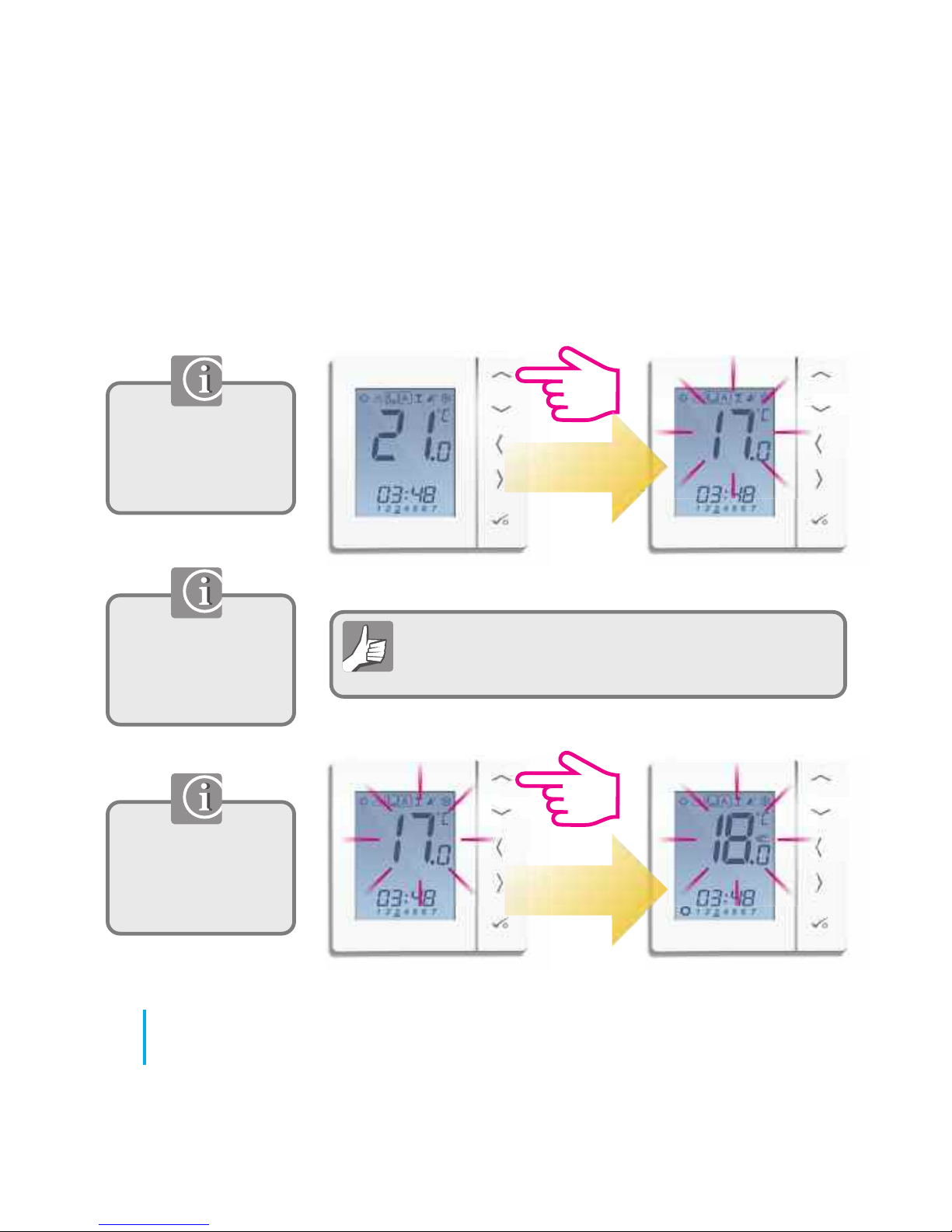
Use the up or down
arrow key to view
your program set
temperature.
The temporary
override is applicable
to the thermostat
being changed only.
Use the up or down
arrow key to adjust
the temperature to
the setting you desire.
Temporary override allows you to increase the
temperature or decrease it to the desired setting until
it reverts back on the next program time.
PRT, Group Control Thermostat and Group Thermostat.
76
JGSTATW Instruction Manual
User Guide - Temporary Override
Page 77
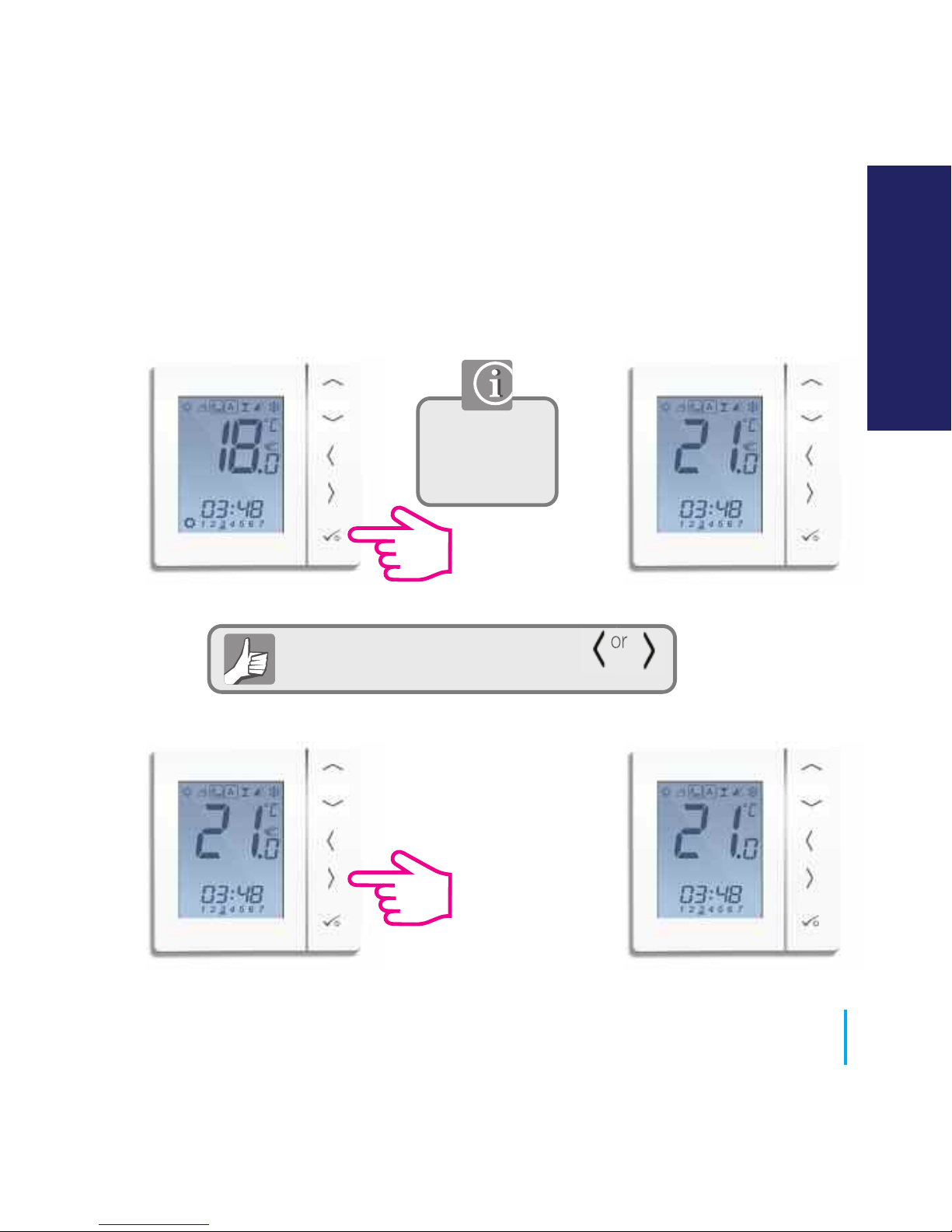
To cancel temporary override press or
See below.
PRT, Group Control Thermostat and Group Thermostat.
Confirm the
temporary set
temperature.
77
www.speedfitUFH.co.uk
User Guide - Temporary Override
USER GUIDE
Page 78
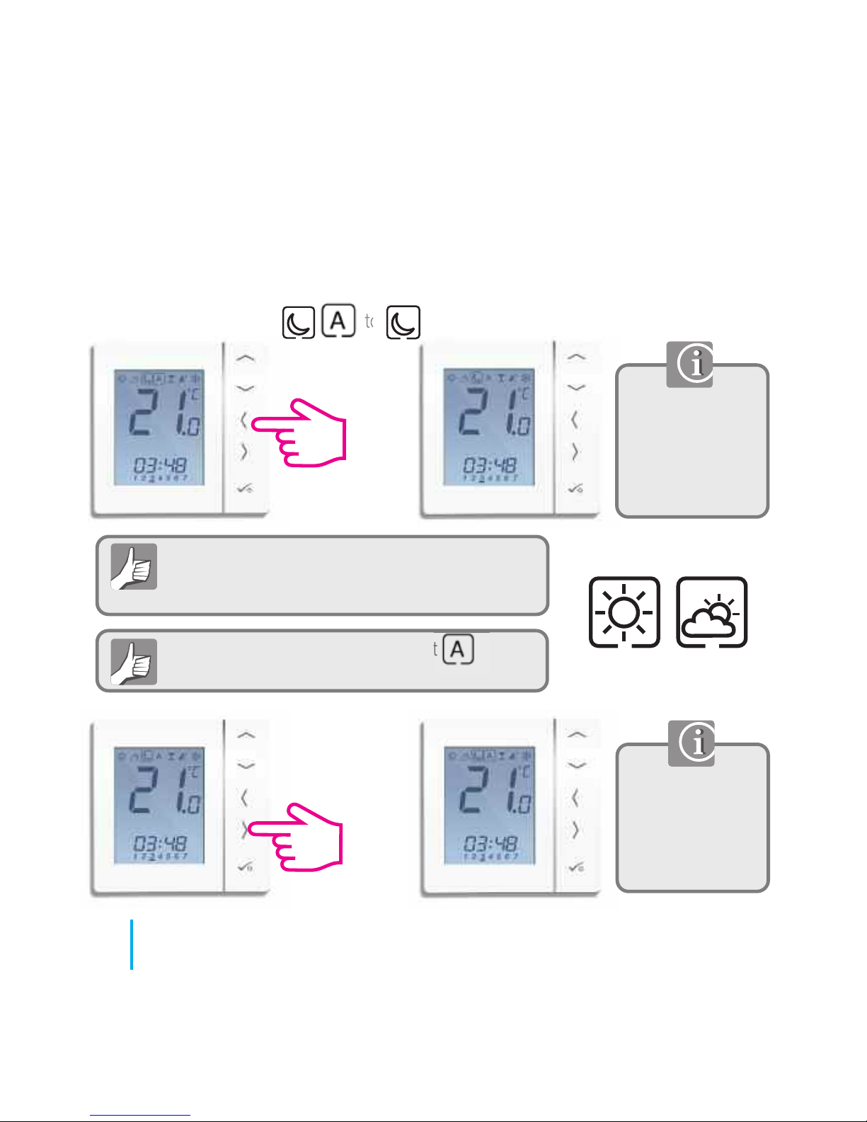
To cancel permanent override select
See below.
Permanent override in a Group Control Thermostat
will also affect the Group Thermostats unless they
are removed from the group. See page 82.
Move from to
Use the up or
down arrow key to
view your set
temperature. See
page 71.
To adjust your
permanent override
temperature, follow
the steps on page
71.
Repeat for
if required
PRT and Group Control Thermostat Setting permanent low temperature.
78
JGSTATW Instruction Manual
User Guide - Permanent Override
Page 79
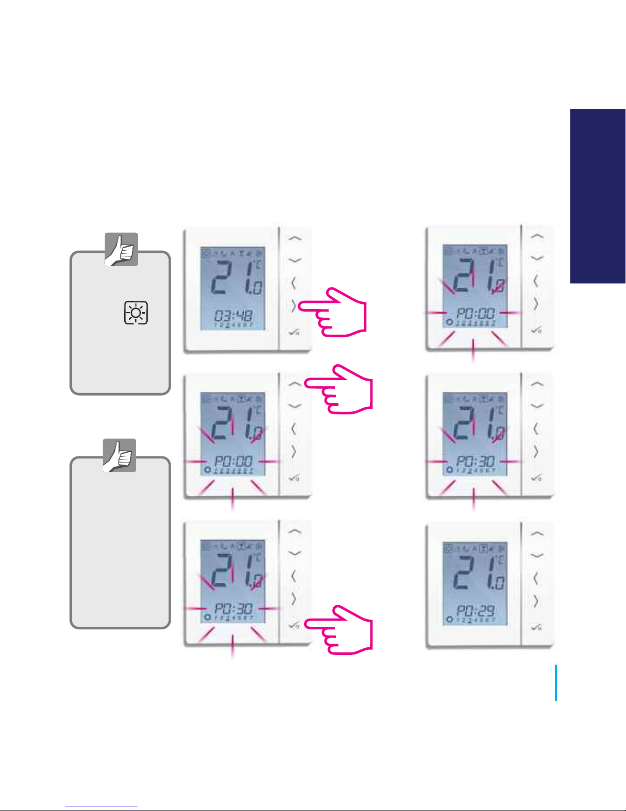
The party mode
is an option that
enables
temperature
for a period of
time you select
up to 9hr 50min.
Use the right
arrow to select
the party mode.
Use the up
arrow to select
the hr/min.
Press tick to
confirm and
it will start to
count down.
Party Mode set in
a Control Group
Thermostat will
also affect group
thermostats
unless they are
removed from
the group.
See page 82.
PRT and Group Control Thermostat.
79
www.speedfitUFH.co.uk
User Guide - Party Mode
USER GUIDE
Page 80
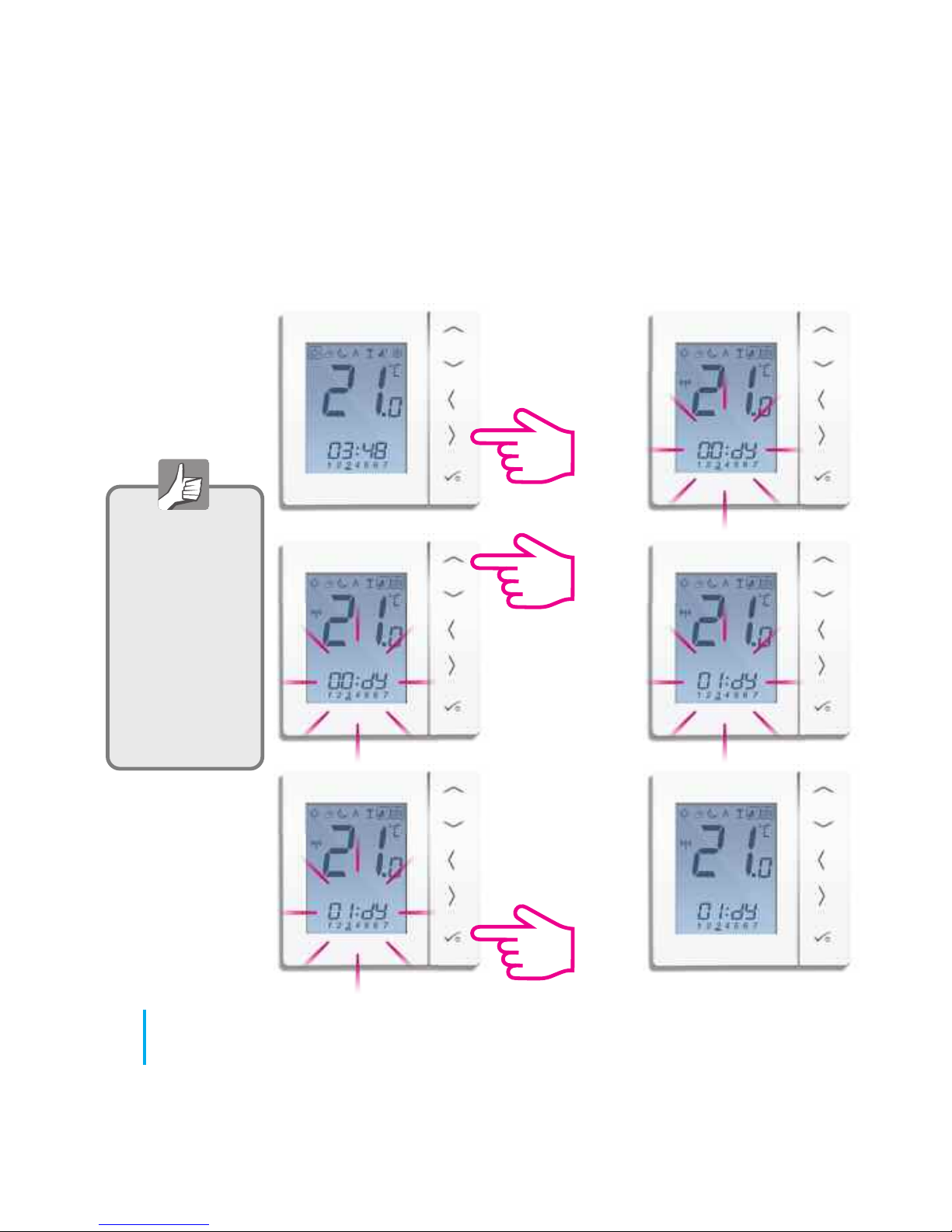
Use the right
arrow to select
the holiday mode.
Use the up
arrow to select
how many days
to be off for.
Press tick to
confirm and it will
start the holiday
count down.
Holiday set in a
Group Control
Thermostat will
also affect group
thermostats
unless they are
removed from
the group.
See page 82.
80
JGSTATW Instruction Manual
User Guide - Holiday Mode
Page 81
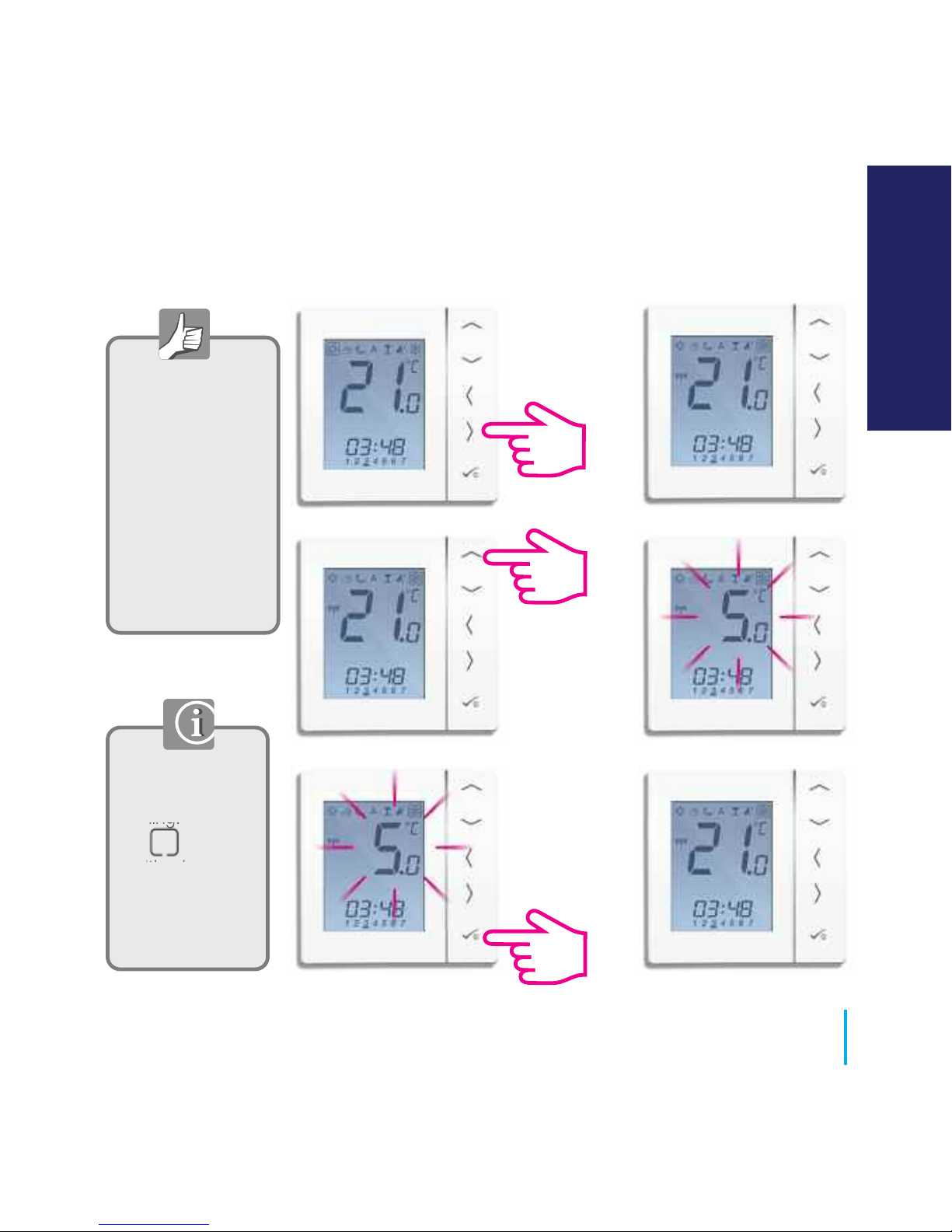
Use the right
arrow to select
the frost mode.
Use the up
arrow to select
the frost
protection
temperature.
Press tick to
confirm the set
temperature.
F
rost
p
ro
tection
set
in
a
G
roup
Co
n
trol
T
h
ermo
stat
w
ill
also
af
f
ect gro
u
p
th
ermo
stats
u
n
less th
ey
are
remov
ed
f
rom
the
group.
See page 82.
81
www.speedfitUFH.co.uk
User Guide - Frost Protection
Frost protection is
not available in
Cooling. Moving
the to this
position in
Cooling will
switch the
thermostat to off.
USER GUIDE
Page 82
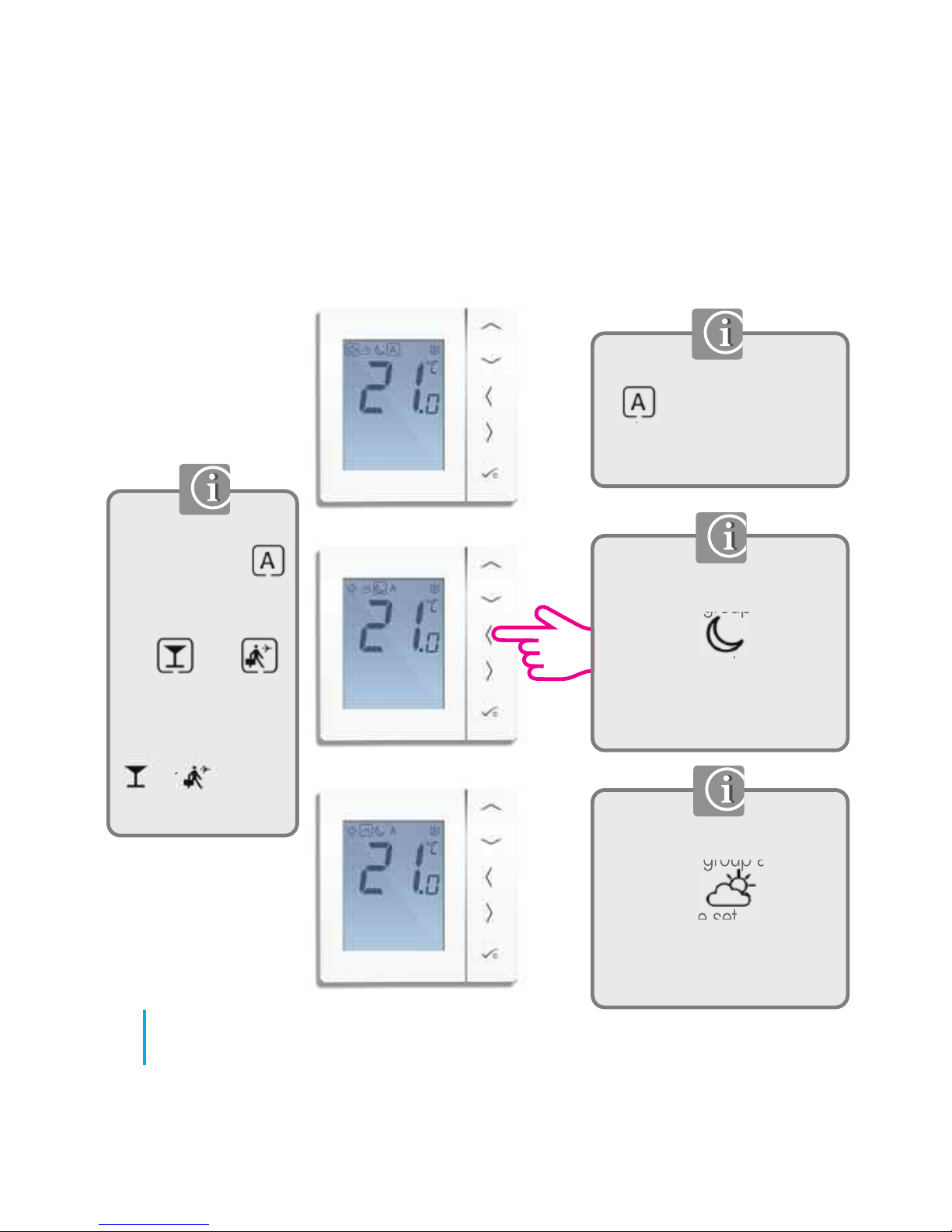
When a group thermostat is
in it will follow the
mode status of the group
control thermostat.
The group thermostat has
now left the group and is in
permanent
To adjust the set
temperature, please refer to
pages 71 - 72.
The group thermostat has
now left the group and is in
permanent
To adjust the set
temperature, please refer to
pages 71 - 72.
When a group
thermostat is in
and the group
control thermostat
is in or
then the group
thermostat will
follow this mode.
or will be
displayed.
82
JGSTATW Instruction Manual
User Guide - Group Thermostat Overview
Page 83
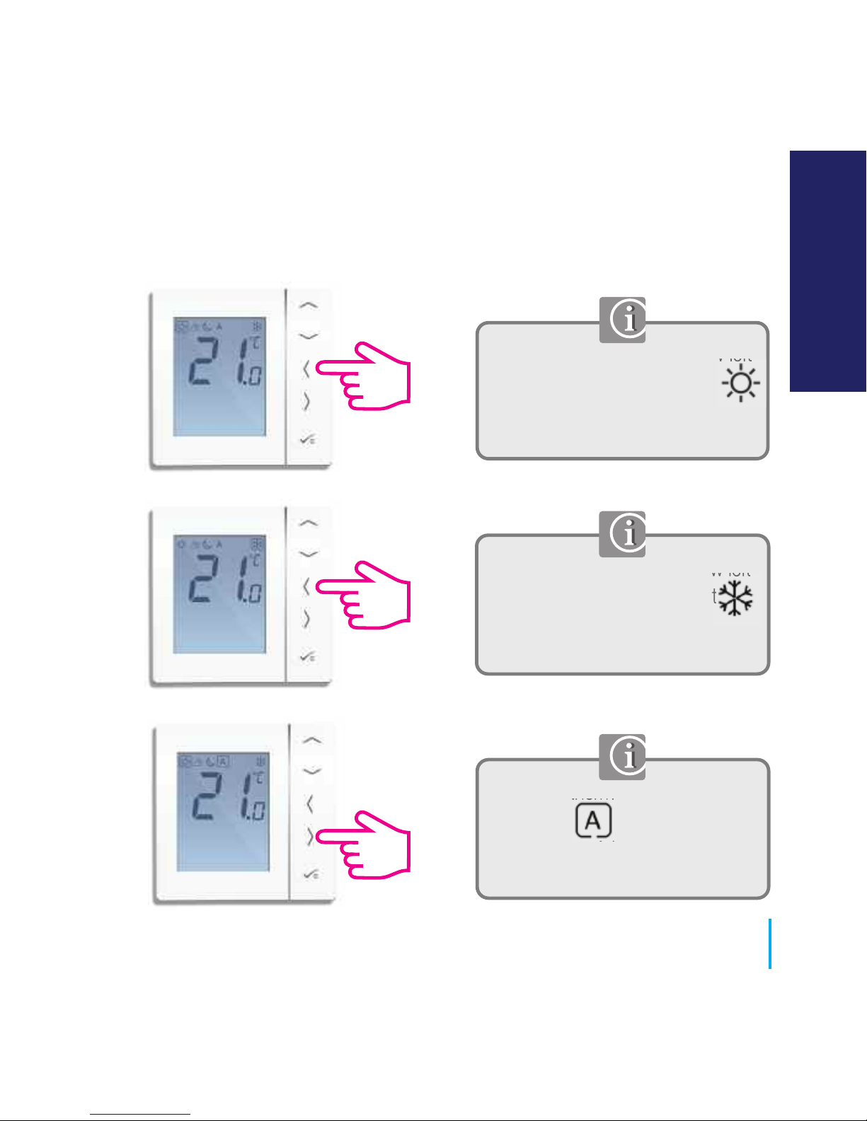
The group thermostat has now left
the group and is in permanent
To adjust the set temperature,
please refer to page 71 - 72.
The group thermostat has now left
the group and is in permanent
To adjust the set temperature,
please refer to page 71 - 72.
The group thermostat has been
returned to it will follow the
mode status of the group control
thermostat.
83
www.speedfitUFH.co.uk
User Guide - Group Thermostat Overview
USER GUIDE
Page 84
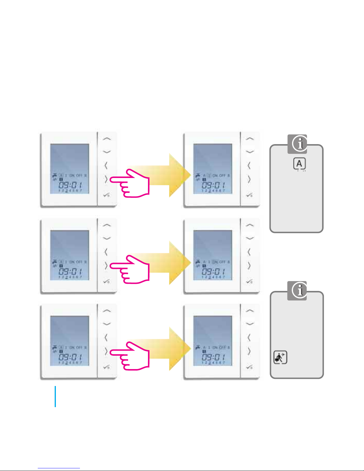
2
3
Mode selection.
Hot water will
follow Holiday
mode from the
Group Control
Thermostat.
will be
displayed.
When is
selected, the
hot water timer
will follow the
program
schedule. See
page 86.
Hot water will be
on once per day.
Hot water will be
continuously on.
Hot water will be
continuously off.
84
JGSTATW Instruction Manual
User Guide - Hot Water (Optional) Mode Selection
Page 85
85
www.speedfitUFH.co.uk
User Guide - Hot Water Boost
USER GUIDE
Page 86
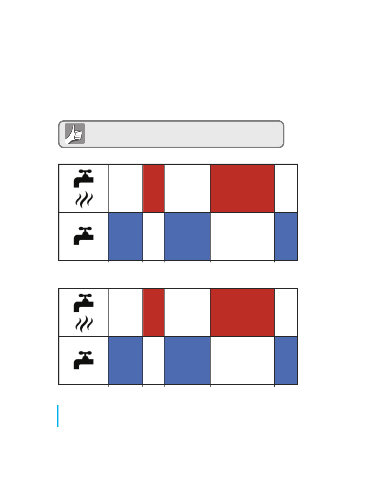
12.00 6.00 8.00 18.00 22.00
ON ON
OFF
OFF OFF
12.00 6.00 8.00 18.00 22.00
Saturday and Sunday
Monday to Friday
ON ON
OFFOFF OFF
Your hot water timer comes preset with the times below.
These can be adjusted. See next page.
86
JGSTATW Instruction Manual
User Guide - Default Hot Water Schedule
Page 87
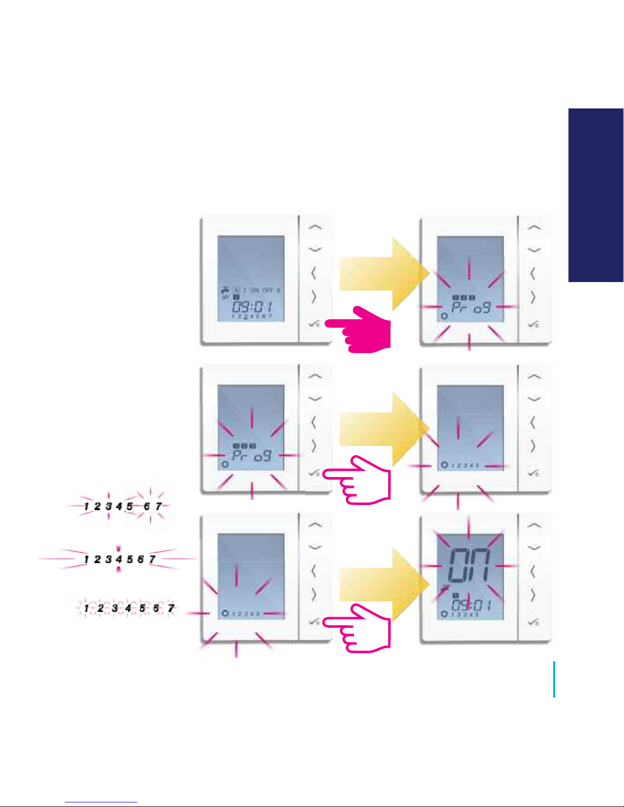
5/2
7 Days
Individual
87
www.speedfitUFH.co.uk
User Guide - Setting Hot Water Times
USER GUIDE
Page 88
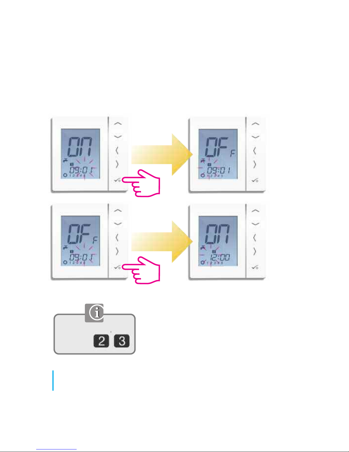
88
JGSTATW Instruction Manual
User Guide - Setting Hot Water Times
Repeat these steps for
programs
Page 89
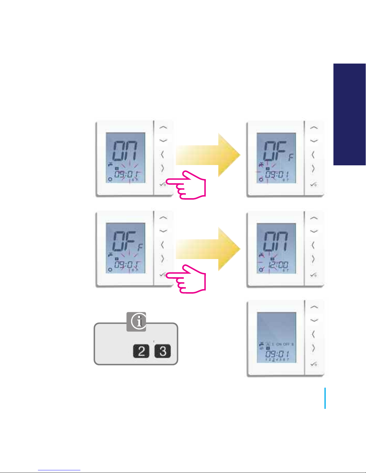
Repeat these steps for
programs
89
www.speedfitUFH.co.uk
User Guide - Setting Hot Water Times
USER GUIDE
Page 90

90
JGSTATW Instruction Manual
Installer Notes
Page 91

91
www.speedfitUFH.co.uk
Installer Notes
Disclaimer
Customers that choose to operate their heating remotely using JG Aura Range technology via their
personal computer, tablet or smart phone device(s) will be entering into a contract with Salus Controls
plc (“Salus”), which is a third party supplier of the software. John Guest Ltd and affiliates within the
John Guest group of companies from time to time (the “John Guest Group”) make no representations
or warranties of any kind about the reliability or suitability of the software or applications provided by
Salus. The John Guest Group disclaims liability (excluding liability for death and personal injury
resulting from negligence) for any loss or damage caused by the software provided to customers by
Salus. Any agreement entered into with Salus is therefore strictly at your own risk.
Page 92

John Guest Speedfit Limited
Horton Road, West Drayton, Middlesex UB7 8JL, England.
Tel: 01895 449233
Fax: 01895 420321
www.speedfitUFH.co.uk
Technical Help Desk: 01895 425333
,
The above namestyles are all trademarks of John Guest International Limited.
©
John Guest International Limited 2014. All rights reserved.
Z2105/425/1114
and
 Loading...