

Page 1
speedfitUFH.co.uk
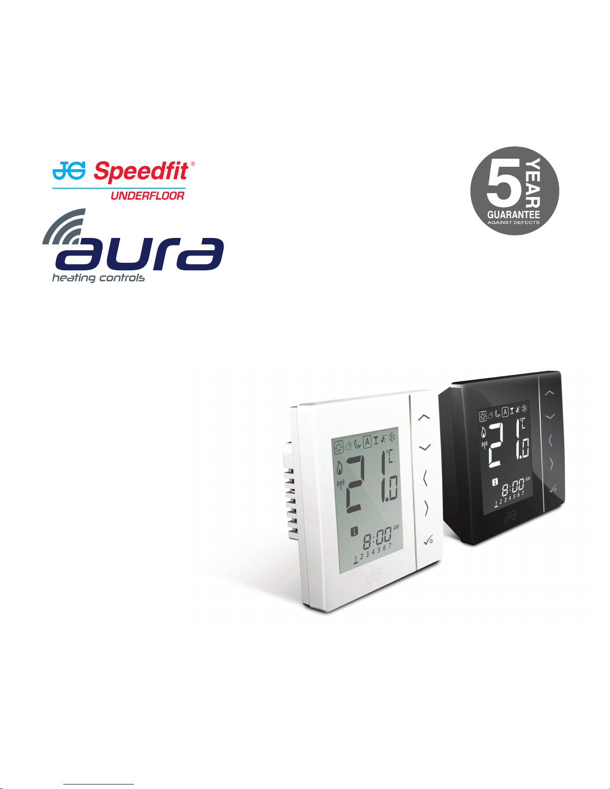
For models:
JGSTATW2W
JGSTATW2B
JGSTATW1W
JGSTATW1B
Quick Set-up Guide
Wireless Thermostats
230v and Battery Operated
Page 2
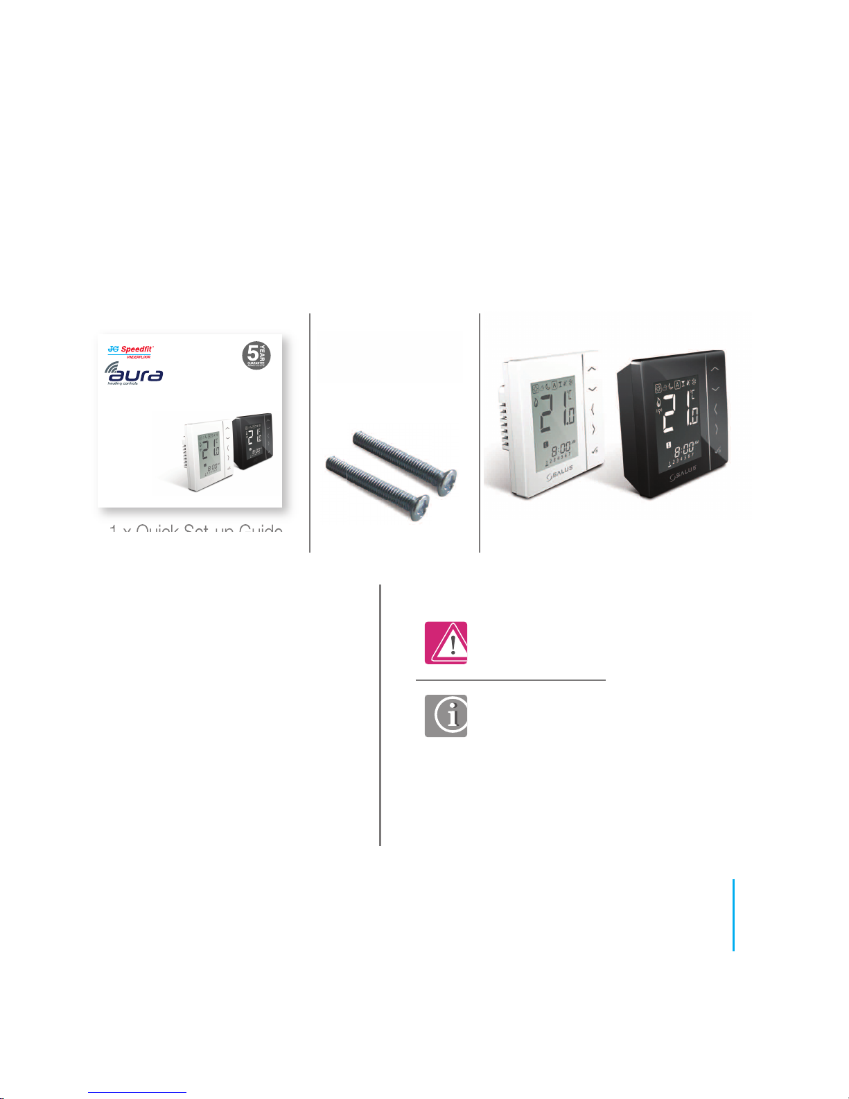
1 x Quick Set-up Guide JGSTATW2
4x AAA Batteries
JGSTATW1Fixing screws
Box contents:
Contents
Quick Set-up Guide:
• Box contents
• Introduction
• Product compliance
• Terminal connections
• Coordinator set-up
• JGBR set-up
• Identifying the Wiring Centre
• PRT quick set-up
• HWT quick set-up
Icons used in this guide:
Safety
Important info
For latest PDF Quick Set-up Guide and
full Instruction Manual please go to
speedfitUFH.co.uk
speedfitUFH.co.uk
For models:
JGSTATW2W
JGSTATW2B
JGSTATW1W
JGSTATW1B
Quick Set-up Guide
Wireless Thermostats
230v and Battery Operated
03
speedfitUFH.co.uk
Page 3
04
JGSTATW1/W2 Quick Set-up Guide
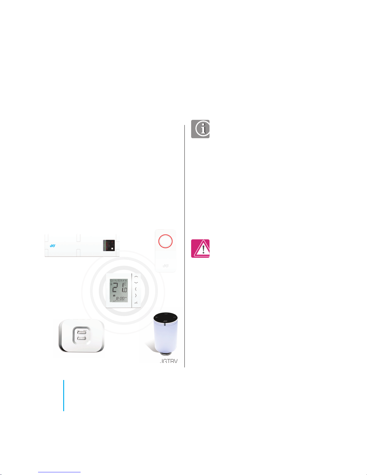
Introduction. Thank you for purchasing
one of our Speedfit Aura Wireless
Thermostat models. It must be used with
the JGCO Wireless Coordinator. The
Wireless Coordinator allows communication
with other devices in the Aura Wireless
system range including wiring centre,
Wireless boiler receiver and Wireless TRV.
Product Compliance. These
products are CE compliant and
meets the following European
Directives:
RoHS2: 2011/65/EU
RED: 2014/30/EU
Declaration of conformity available
at saluslegal.com
Safety Information. Use in
accordance with the regulations.
The JG Aura JGSTATW1/W2 is
to be used for room control of
heating and hot water systems
inside buildings.
JGWCW
JGTRV
JGSTATW1/W2
JGCO
Product compliance & safety information
We hope you enjoy
this product...
JGBR
Page 4
Product compliance & safety information
Emergency. Switch off the
voltage to the individual
thermostat, wiring centre or
complete system.
Sources of danger. The
thermostat must be disconnected
from mains supply before
removing the cover.
Installer parameter settings.
JG Aura wireless thermostats are
equipped with an Installer Parameter
section (see website). This must only
be entered by the installer or a
competent person. Changing these
parameters can have a serious
effect on your heating system.
230 AC
Warning. This product must be
fitted by a competent person.
Installation must comply with the
guidance, standards and
regulations applicable to the
location where the product is
installed. Failure to comply with the
requirements of the relevant
guidance, standards and
regulations could lead to
prosecution, injury or death.
These instructions are applicable to the
Aura models stated on the front cover of
this Instruction Manual only.
Warning. Always isolate the AC
Mains supply before installing or
working on any components that
require 230v AC 50Hz supply.
05
speedfitUFH.co.uk
Page 5
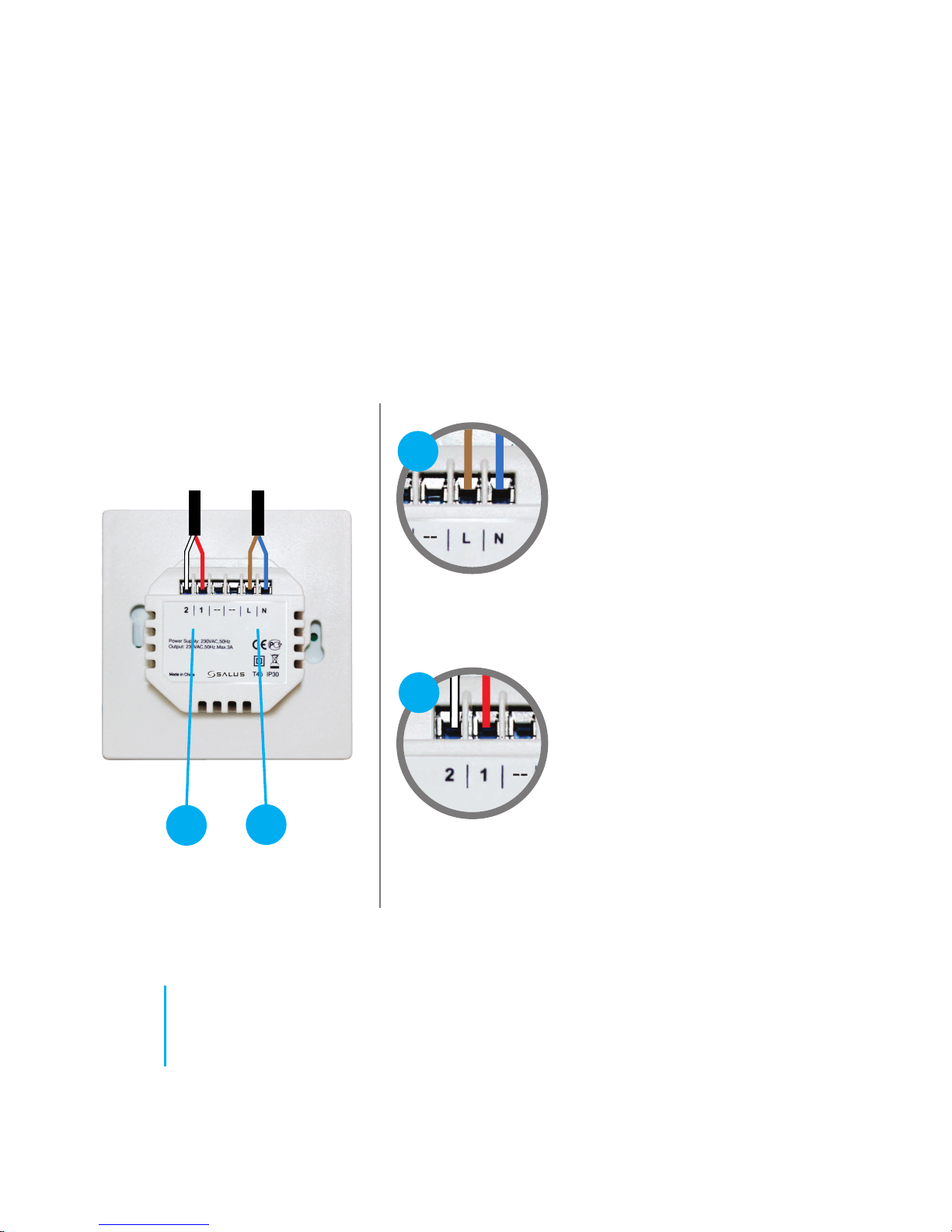
Rear of unit
Power Terminals 230v AC.
Used for supplying power to the
unit. 230v supply can be sourced
from the wiring centre or any
convenient 3amp fused supply.
Probe / Hot Water Cylinder
Terminals. Can be used for
external Air or Floor probe when
configured as thermostat. Can
also be used for Cylinder
thermostat connection when
configured as a Timer.
Understanding your terminal connections
Terminal connections
(JGSTATW2) - 230v powered
2
1
1
2
06
JGSTATW1/W2 Quick Set-up Guide
230VACVS10BRF
Page 6
07
speedfitUFH.co.uk
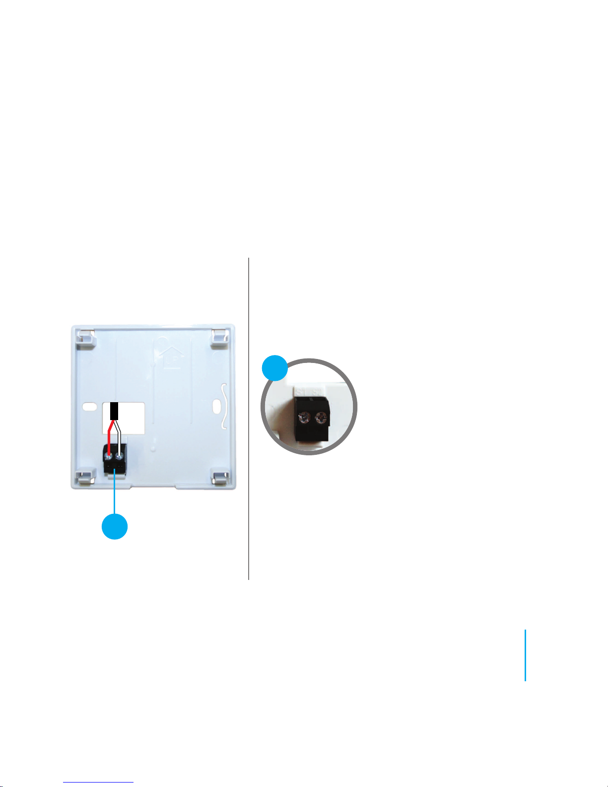
Rear of unit
Sensor Terminals.
Can be used for an external Air
or Floor sensor when configured
as thermostat. Can also be used
for Cylinder thermostat when
configured for HW.
Understanding your terminal connections
Terminal connections (JGSTATW1)
1
1
S1 - S2
Page 7
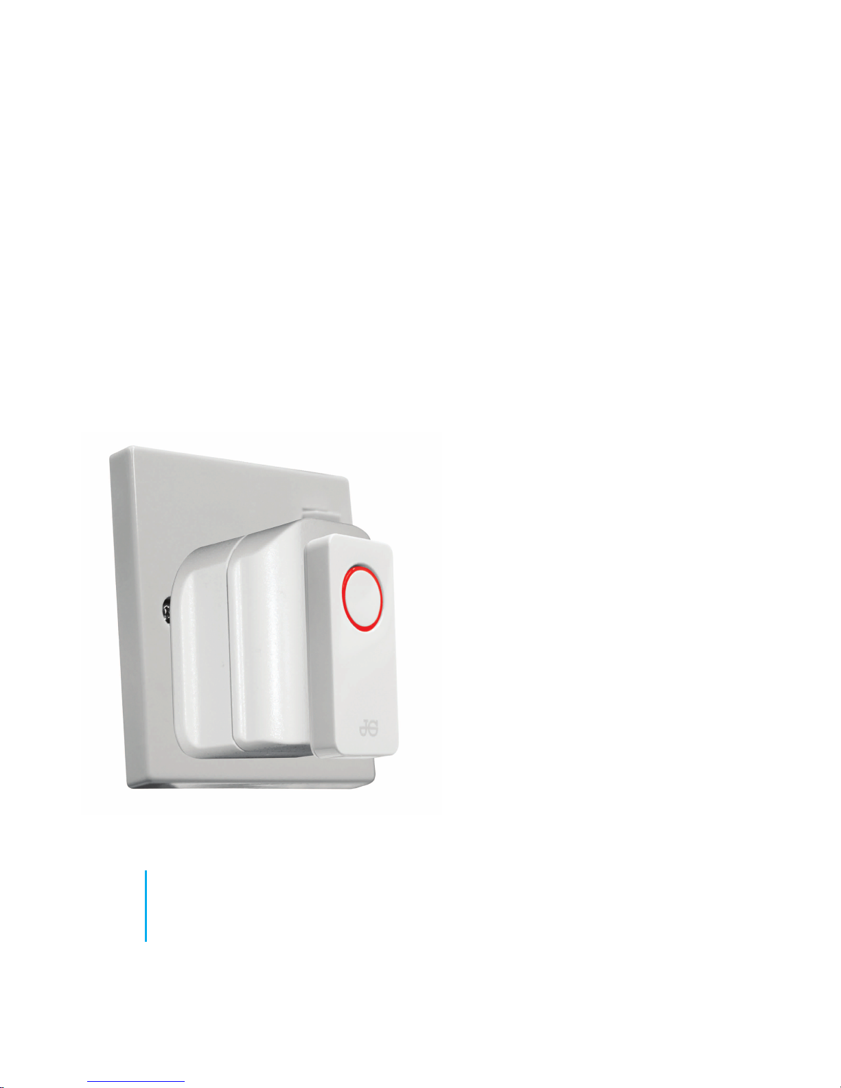
To commence system installation, press and hold the button for 5 seconds. The button
will start to flash red indicating that the Zigbee network is ready to accept JG Aura devices.
For full Coordinator instructions please see seperate literature or go on line to
speedfitUFH.co.uk
Coordinator set-up
08
JGSTATW1/W2 Quick Set-up Guide
Page 8
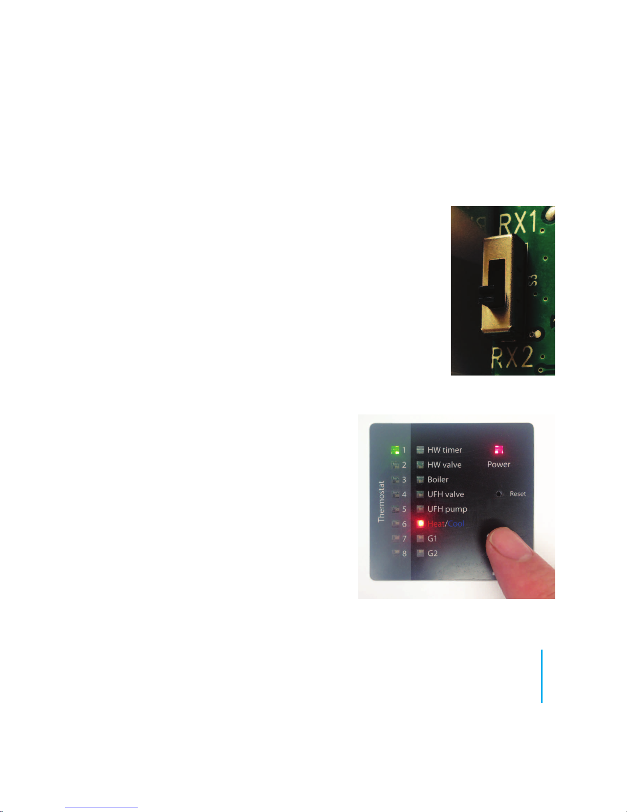
After setting up, the Coordinator will assign the
Wiring Centre a number. This is because more
than 1 Wiring Centre may be used on a project.
Pressing the network button will illuminate the
relevant number. The example shown is for
Wiring Centre 1. If 1 and 2 are lit it would be
Wiring Centre 2.
The JGBR default setting is RX1 (Wireless Boiler Receiver). In this
mode, the JGBR will switch on the boiler in response to a call for heat.
To set as a wireless receiver, switch to RX2. The wireless receiver will
be paired to just one chosen thermostat on the network. This
thermostat will switch the wireless receiver when there is a call for heat.
JGBR set-up -
Wireless Boiler Receiver or Wireless Receiver
Identifying the Wiring Centre
09
speedfitUFH.co.uk
Page 9
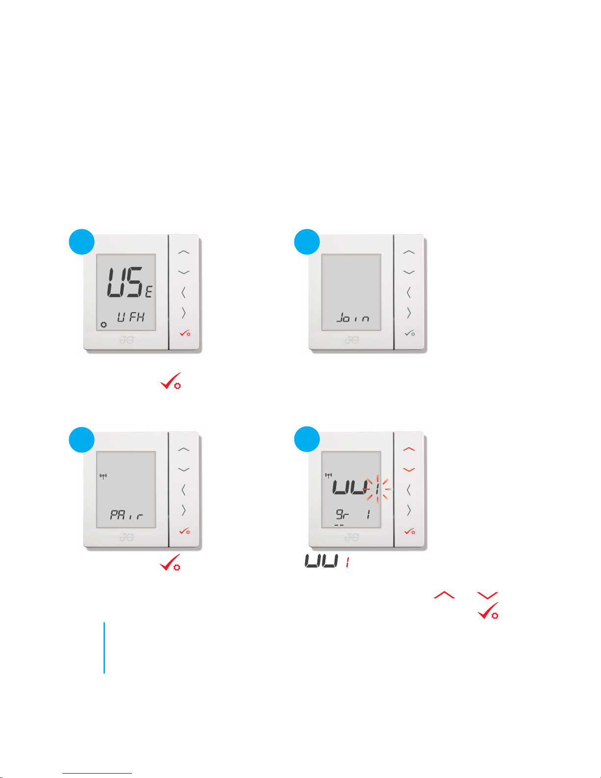
Programmable Room Thermostat paired with
Wireless Wiring Centre
1
2
3
Start up screen as shown.
Press CONFIRM
Prior to pairing refer to Coordinator start up on page 8.
Press CONFIRM
4
No action required.
icon flashing to request the number of the
Wiring Centre you wish to pair with (see Identifying
Wiring Centre - page 9). Use and to select
the required number. Press CONFIRM
10
JGSTATW1/W2 Quick Set-up Guide
Page 10
5
6
7
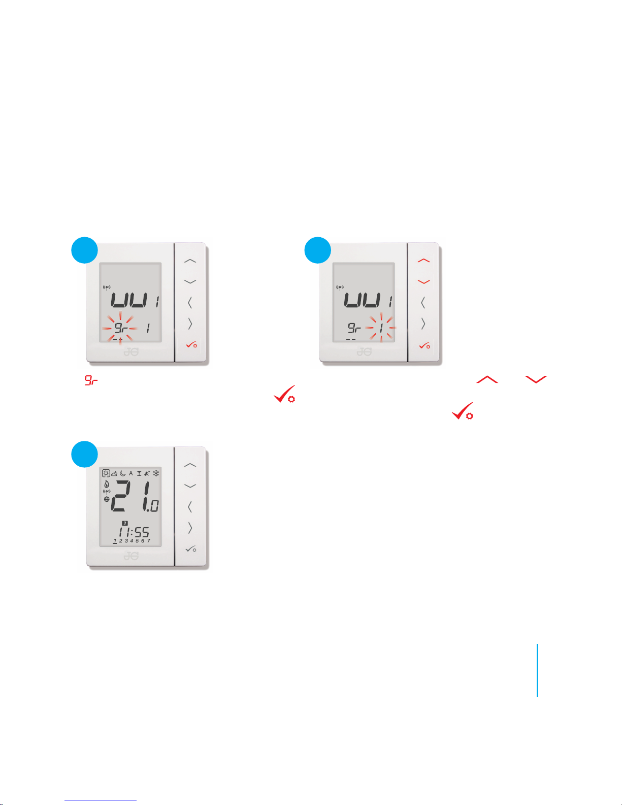
requesting group number. No action
needed in this instance. Press CONFIRM
Zone number flashing. Using the and to
set the wiring centre zone you want the thermostat
to control. Press CONFIRM
Thermostat returns to home screen and the pairing is finished.
Testing: Set thermostat to high temperature and wait for a call for
heat. Check that the thermostat is communicating with the correct
zone on the paired wiring centre.
11
speedfitUFH.co.uk
Page 11
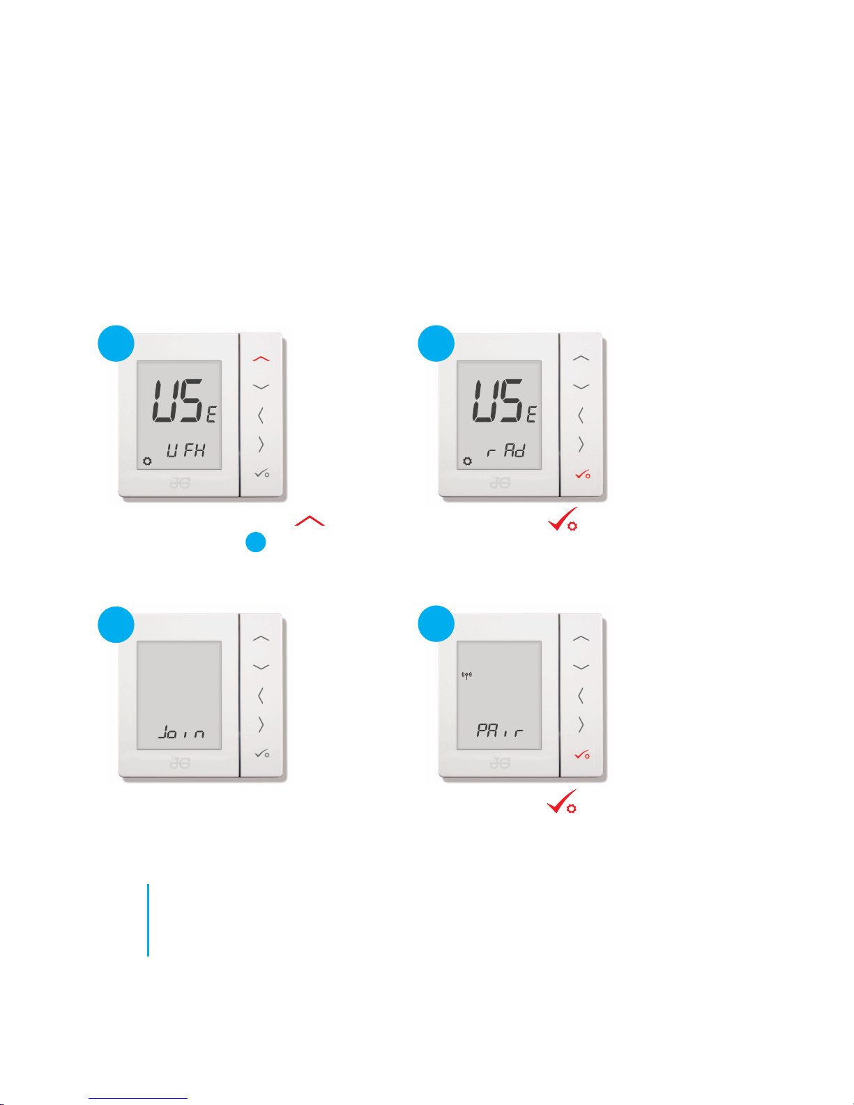
Programmable Room Thermostat
paired with
Wireless TRV
1
2
3
From start up screen press .
Screen will scroll to .
No action required.
4
Press CONFIRM
Press CONFIRM
Prior to pairing refer to Coordinator start up on page 8.
2
12
JGSTATW1/W2 Quick Set-up Guide
Page 12
5
7
6
8
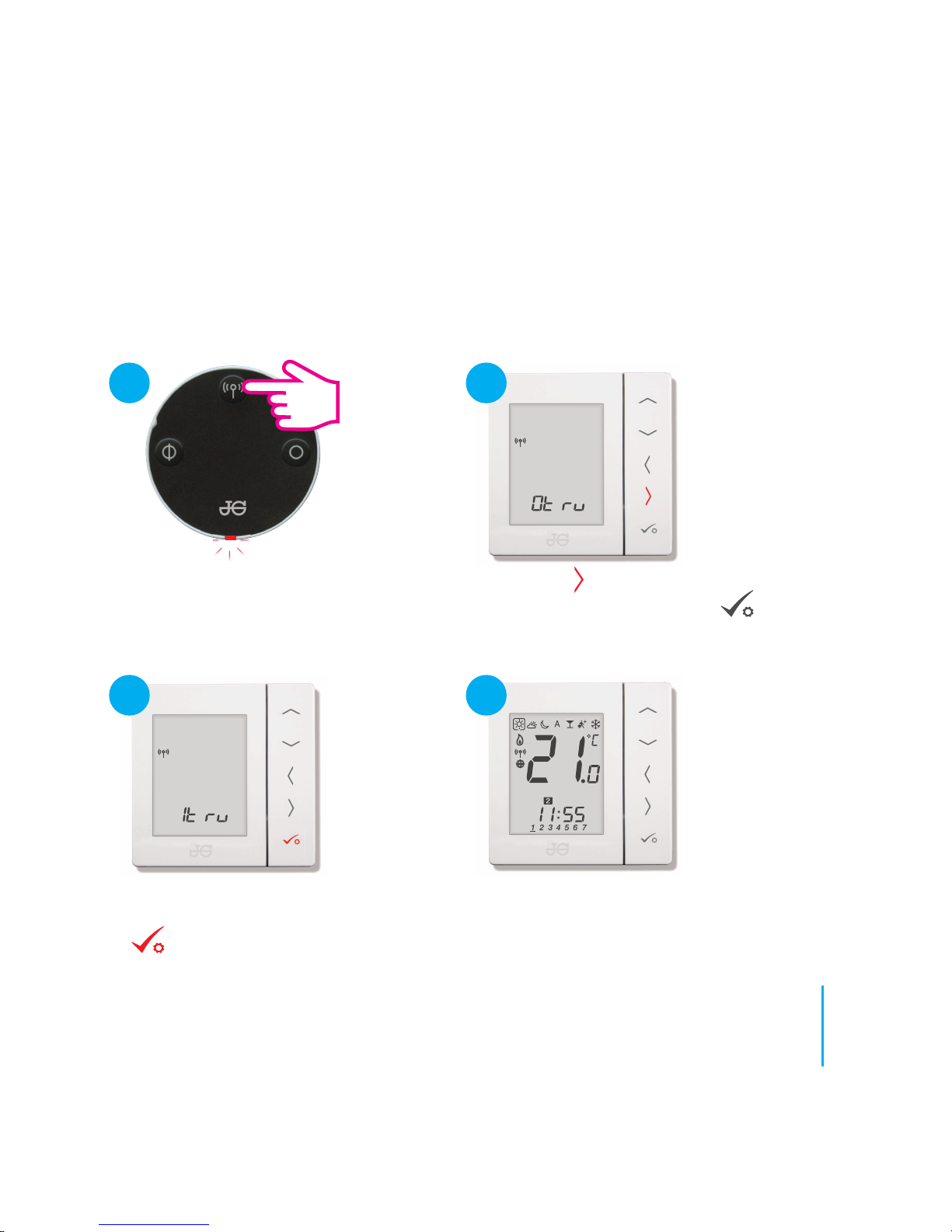
Thermostat returns to home screen.
Testing: Set to
call for heat. Check TRV’s are opening and Boiler
Receiver is receiving the signal. Turn down the
thermostat and check TRV’s shut and boiler receiver
turns off.
Next press arrow on thermostat to start pairing
process. Do not press Confirm as it will abort
the pairing process and user will have to start again.
Press Pairing Button on TRV(s) for 10
seconds until pairing light on the TRV starts
to flash. Maximum of 6 TRV’s can be paired
at the same time.
If thermostat only finds 1 to 5 TRV’s it will
continue to search until user presses Confirm
. If the maximum 6 TRV’s are found the
thermostat will automatically finish pairing
and return to the home screen.
13
speedfitUFH.co.uk
Page 13

Programmable Room Thermostat
paired with Wireless
Boiler Receiver (RX1)
1
2
3
Start up screen as shown. Press and hold
bottom 3 buttons until next screen is
shown.
Press to scroll to .
4
Press CONFIRM
Press CONFIRM
2
Prior to pairing refer to Coordinator start up on page 8.
14
JGSTATW1/W2 Quick Set-up Guide
Note: See page
7 for setting of
JGBR to RX1.
Page 14
5
6
7
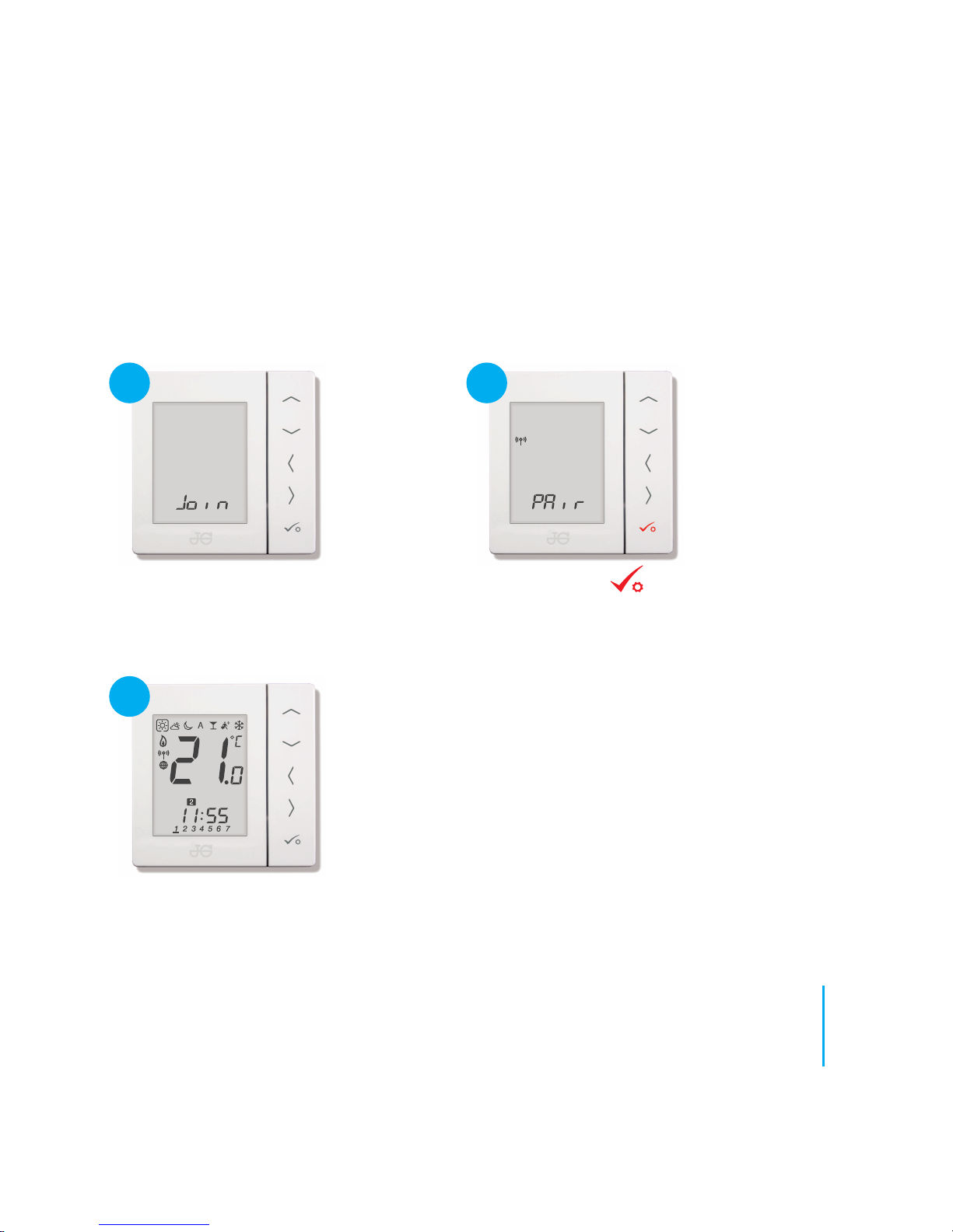
No action required.
Thermostat returns to home screen. Testing: Set thermostat to high
temperature and wait for a call for heat. Check the Wireless Boiler
Receiver is receiving the signal and switching on and off.
Press CONFIRM
15
speedfitUFH.co.uk
Page 15
4
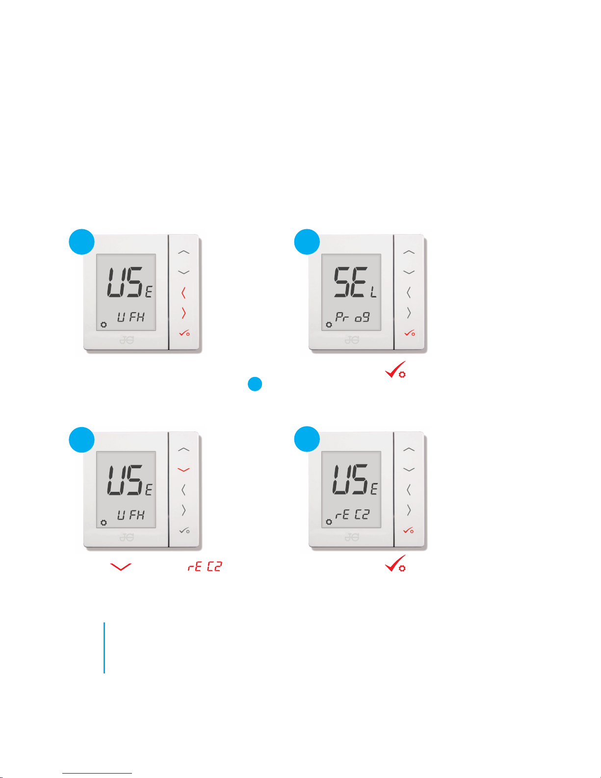
Press CONFIRM
Programmable Room Thermostat
paired with Wireless
Receiver (RX2)
1
2
3
Press to scroll to .
Press CONFIRM
Prior to pairing refer to Coordinator start up on page 8.
Start up screen as shown. Press and hold
bottom 3 buttons until next screen is
shown.
2
16
JGSTATW1/W2 Quick Set-up Guide
Note: See page
7 for setting of
JGBR to RX2.
Page 16
5
6
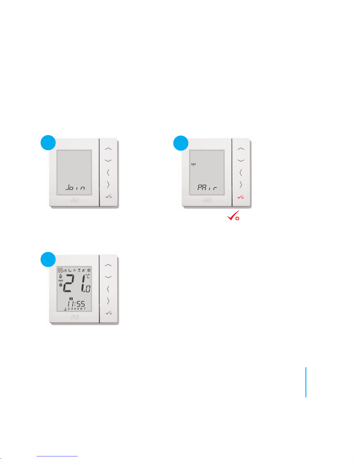
No action required.
7
Thermostat returns to home screen. Testing: Set thermostat to high
temperature and wait for a call for heat. Check the Receiver is receiving
the signal and switching on and off. If there is also a boiler receiver fitted
to the network check that this is responding.
Press CONFIRM
17
speedfitUFH.co.uk
Page 17
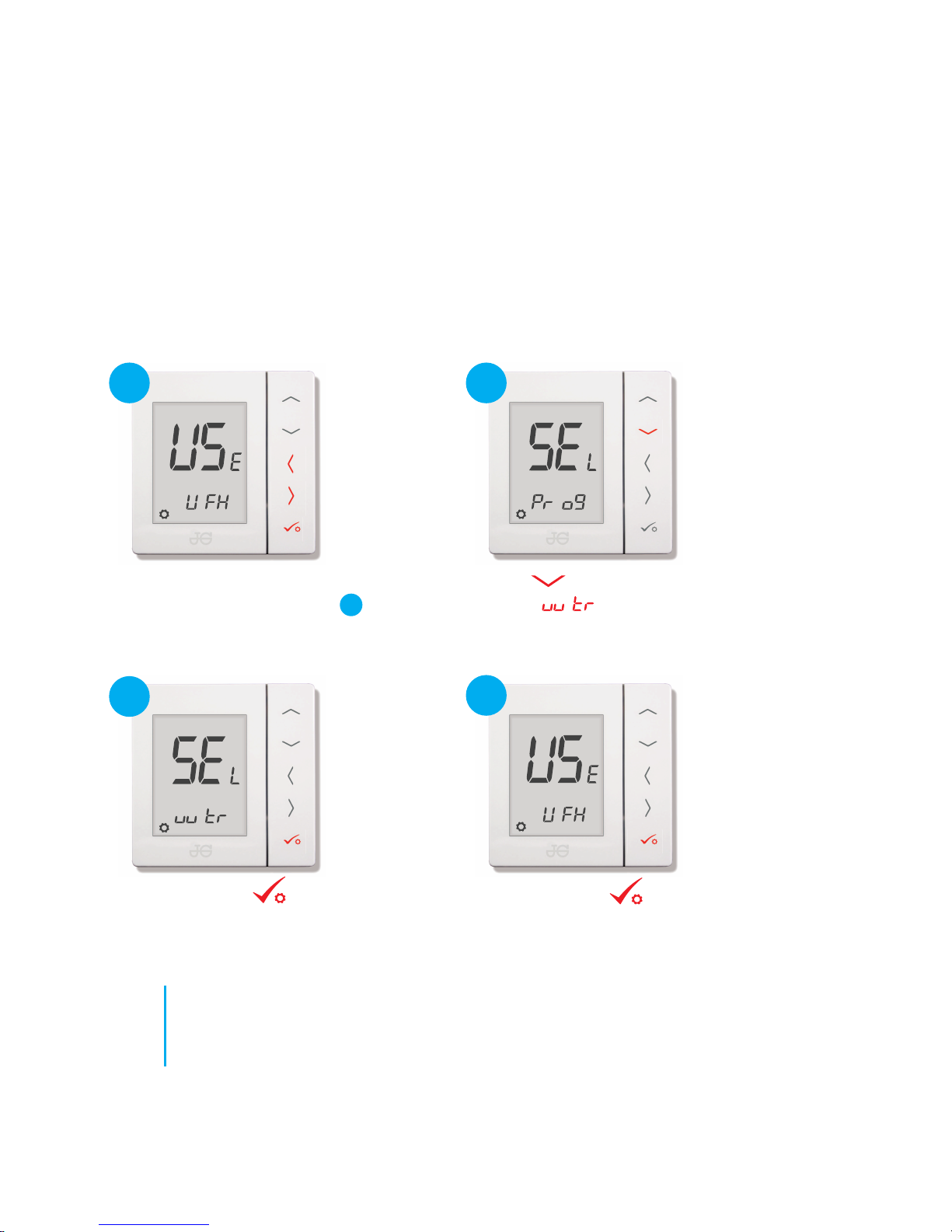
Hot Water Timer paired with Wiring Centre
Press to scroll to Hot Water Timer
screen
1
2
3
Press CONFIRM
4
Press CONFIRM
Start up screen as shown. Hold bottom
3 buttons to scroll to screen .
Prior to pairing refer to Coordinator start up on page 8.
2
18
JGSTATW1/W2 Quick Set-up Guide
Page 18
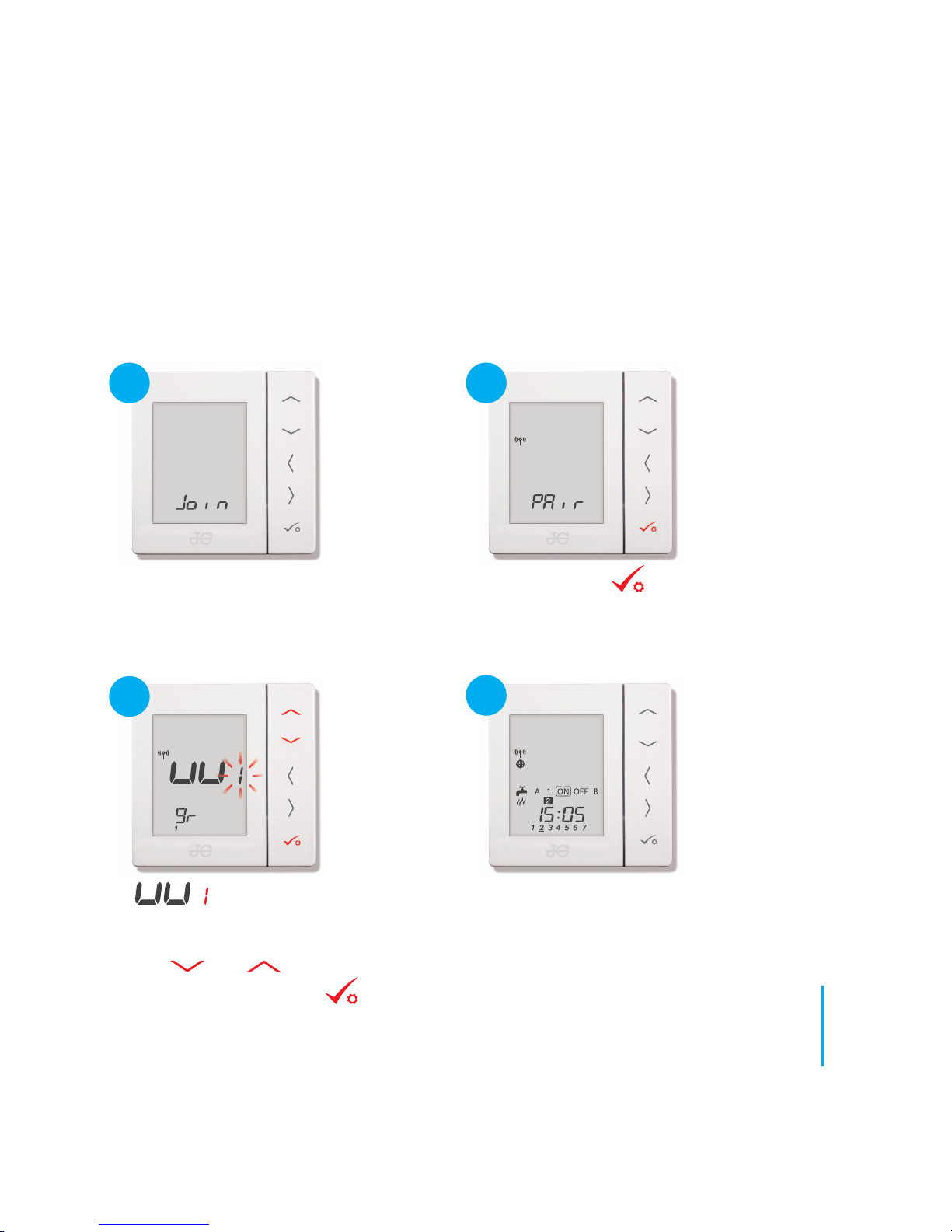
5
6
7
8
Hot Water Timer displays home screen
.
Testing: Set timer to [ON] and check that Hot
Water Timer LED is lit on wiring centre.
Note: Hot Water
Timer will
automatically
join Group 1.
No action needed.
Pr
ess
CO
NF
I
R
M
icon flashing to request the
number of the Wiring Centre to pair with
(see Identifying Wiring Centre - page 9).
Use and to select the required
number. Press CONFIRM
19
speedfitUFH.co.uk
Page 19

John Guest Speedfit Limited
Horton Road, West Drayton, Middlesex UB7 8JL, England.
Tel: 01895 449233
Fax: 01895 420321
speedfitUFH.co.uk
Technical Help Desk: 01895 425333
,
The above namestyles are all trademarks of John Guest International Limited.
©
John Guest International Limited 2016. All rights reserved.
Z2105/458/0716
and
 Loading...