

Page 1
User Manual
MODEL
101MF
Pump
MODEL
101MP
101MF Tested and Certified by NSF International NSF/ANSI Standard 58 for the Reduction
Claims Specified on the Performans Data Sheet.
Member, Water Quality Association
Page 2
Page 3

Osmosis Osmotic Pressure,
Reverse Osmosis (RO) Process
Semi-permeable mebrane and solution the basics of the asmosis event.
Semi-permeable mebrane which is formed of a thin diaphragm or thin film,
lets some of molecules and ions pass, but does not let some others. Cell
mebranes and egg mebrane are examples of membrane.
Solutions is a homogeneous mixture formed of several chemical subtances. In
other words, it is the diffusion of a substance in another substance in the form
of particles which are too small to be visible. This diffusion is called dissolving,
and obtained mixture is called solution. Generally, the one with less amount
in the mixture is called the solute and the one with high amount is called the
solvent. Water is better solvent than any other one in nature. It dissolves many
solid, liquid and gaseous materials. Water (sea water) and suğar water (tea) are
the most commonly known solutions.
Many solid substance are found as dissolved in water in nature. In other words,
water we use is a solution. Water molecules in this solution are constantly in
motion. As the amount of dissolved solid sunstance increases. In water with
high concentration, i.e. in water with higher solid substance , less molecules
are present when compared with water same volume but less concentration,
as a consequence, since the number of molecules in motion is less, also the
thermal interior energy becomes less. That is, the energy of the solution with
lower concentration is higher.
1
3
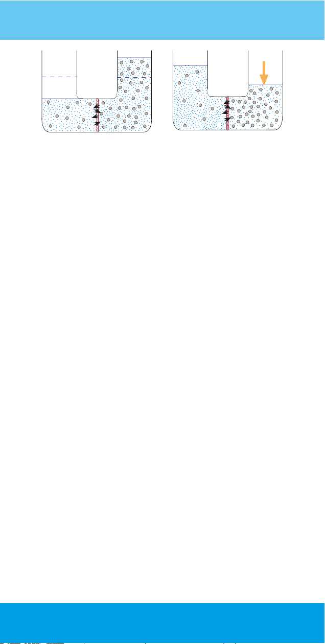
Before Osmosis
Solvent (water)
Solute (solid matter particles)
Passage of water molecules through the membrane
Lower Concentration
1-
(higher osmotic pressure and higher internal energy)
Higher Concentration
2-
(lower osmotic pressure and lower internal energy)
Membrane (semi-permable)
3-
2
3
Page 4
Pressure
After Osmosis
Figure 1. Osmosis and Reverse Osmosis
When semi-permeable membrane is placed in between two water column of
same volume but different concentrations in a U-tube, while water molecules
pass through the pores, several solid material particles having bigger size in
dissolved state can not pass through those pores. Passing rate is related to
concentration ratio, temprature and pressure. This passing continues until the
concentration ratio at both sides are equal. The pressure originating from the
potential energy of this increasing water column is balanced by the Osmotic
Pressure. Thet is to say, internal enetgy on the side with lower concentration is
balanced by the potential ebetgy of the excess in the water column on the side
with higher concentration.
On the condition the if a pressure equal to the pressure to be formed by the
excess in the water column is applied to the side with higher concentration, this
phenomenon called Osmosis does not take place. Furthermore, if a pressure
higher than this level is applied, Osmosis phenomenon is reversed. In spite of the
fact that amount is less, water molecules in the side with higher concentration
start to pass to the side with lower concentration. This phenomenon realized by
force of pressure is called Reverse Osmosis.
Reverse Osmosis is used to separate the solid matters dissolved in water. The
purpose in water purification is to convey the water molecules in water with high
concentration (polluted water) to the water side with lower concentration. Osmosis
take place conversely. In Reverse Osmosis, osmotic pressure surmounted by
application of pressure and the phenomenon is reversed and the purpose is achieved.
Reverse Osmosis
Reverse Osmosis (RO) Water
Treatment Systems
There are systematic equipment designed in order to abtain lower concentration
water (clear potable water) by using the method of reverse osmosis from
higher concentration water (polluted mains water) It is possible to reverse
the osmosis phenomenon which is a natural incident, by applying pressure.
When pressurized water is passed through the membrane wrapped artificial
rollers, most of the solid particles are held and disposed together with waste
water. Water with much lower concentration passing through thin membrane
pores is used as potable water. Before water enters into the membrane, in
order for the rough residues and chloride which is used in water disinfection
to be held, a pre-filtration proces such as sediment filter, carbon filter is usded.
4
-
Page 5
Post carbon filter is applied in order to clean up the taste of water by adding into water
coming out of the membrane, some helpful minerals.
Components such as those filters applied before and aſter the membrane, fittings
connecting those to each other, pump used to increase the pressure, switches, fresh
water storage tank and body, etc. constitue the system. There may be various
configurations of this system. Basically, it is composed of pre-filtration, mambraine
which is the main component of the system where reverse osmosis event takes
place, and storage of water. Aura Cebilon Plus RO system is composed of 3 pre-filtration,
membrane, pH regulating post filter, pump set and a water tank.
Parts and Functions
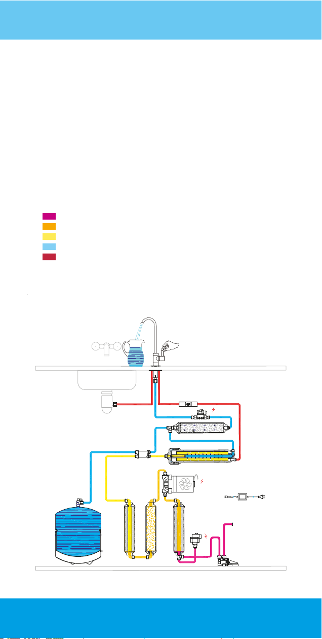
City water
The water free of solid particules
The water free of solid particules and chlorine
Potable water
Waste water
14
WasteWater
7
12
1 Water Leakage Stopper
2 Low Pressure Switch *
3 5 Micron Sediment Filter
4 Pressure Pump *
5 Granular Activated Carbon Filter
6 1 Micron Sediment Filter
7 Shut-off Valve
8 Membrane Filter
9 Mineral Post Carbon Filter
10 High Pressure Switch *
11 Flow Restrictor
12 Tank Valve
13 Fresh Water Tank
14 Faucet
15 Adaptör (24V DC) *
* Only available in 101MF model.
11
10*
9
8
4*
15*
13
6 5
Figure 2. RO System Diagram
City Water
2*
3
inOut
1
5
Page 6
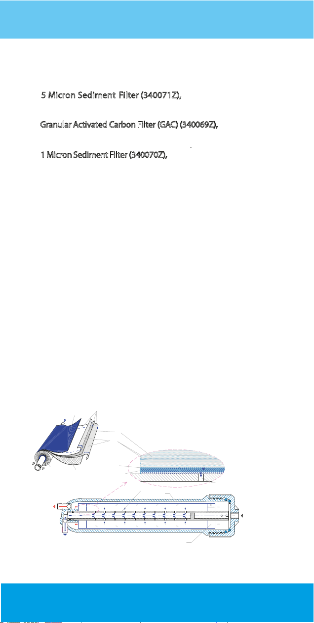
Functions of the Parts
5 Micron Sediment Filter (340071Z), holds the oating matters
and particles in water in order to clarify water.
G
ranular Activated Carbon Filter (GAC) (340069Z), holds free chloride
organic matters and undesired odour.
1 Micron Sediment Filter (340070Z), holds the carbon dust to keep
from plugging of membrane.
Membrane Filter (349004Z02), is where reverse osmosis phenomenon takes place. A long lm made of a semi-permeable material is
folded in a spiral-wound conguration around a permeate colection
tube to obtain double layer lm. A let shaped permeate channel
spacer placed between layers to prevent layers sticking together
and to let clean water ow through between layers into the holes
on tube. Tube is a plastic tube with one end closed, other end lets
water coming from lm bag through holes ow to tank or faucet.
Two long sides and one short side welded with spacer material
together to prevent water leakage from sides expect the tube side.
The membrane lm looks like long bag having all sides welded and
closed expect the end at the tube side. Film bag with an other let
shaped spacer wrapped around the tube together, lm and spacer
form a spiral shape. This spacer constitutes a space between lm
bag wraps to let water ow and reach whole lm surfaces. Some of
water passes into the inside of lm bag by pressure eect, taken o
from outow holes on the tube while polluted water passes by
grazing the lm surfaces in a ow named as crossover ow, some
water moves to the inner part of the lm as fresh water by pressure
eect (Figure 3.).
6
5
4
3
1- Permeate Channel Spacer Folding
2- Spacer
3- Membrane
4- Permeate Channel Spacer
5- Plastic Cover
6- Welded Area
Tube
2
1
Housing
Welded Area
Drain Hole
Inlet
Waste
1
2
Clean
Figure 3. Structure of the Membrane
6
Page 7
Fresh Water Tank has an inner surface coated by a “food contact”
plastic material appropriate to food any provides storage of fresh
water in a hygienic condition.
ank Valve controls inow and outow of water.
T
Mineral Post Carbon Filter (340005Z06) enriches water by adding minerals
before the fresh water stored in the tank of coming directly from the
membrane, ows through the tap and regulates Ph.
Flow Restrictor provides formation of the necessary pressure in
the membrane by restriction the ow, in order to perform
decomposition process. It is placed on the line where waste
water is discharged.
Faucet
is the tap where fresh water is received.
Low Pressure
pressure is below 0.2 bars (3 psi).
Pressure Pump *
ltration, to the level which is necessary for the membrane to
function.
Shut-o Valve, controls the water ow. Cuts o water ow once the
tank pressure reaches to the membrane entrance pressure.
High Pressure
lled up with fresh water reaches 2.6 bars (38 psi).
Pump
mains voltage to 24 V DC.
* Only available in 101MF model.
Switch *, stops the pump when water is cut o or the
, brings the pressure of water passing through pre-
Switch *, stops the pump once the pressure in the tank
Adapter * is the power supply of the pump, it transforms the
Application
This appliance is used to obtain drinking water from the mains
water that have passed through the municipal treatment
processes. This water should be microbiologically safe,
subjected to the necessary disinfection.
If the parameters of the water are within the following ranges
ecient operation of the appliance is ensured.
Systems designed diferently for waters such as sea water,
well water, muddy water etc. with a very high TDS value
are also available.
7
Page 8
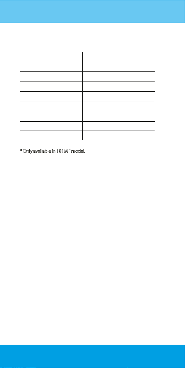
Tecnical Specif ications
ank Capacity
Tank Capacity
Tank Air Pressure
Tank Air Pressure
Daily Capacity 34,03 gpd (128,6 L/d)
Daily Capacity
Purication Rate
Purication Rate
Pump Discharge * 0,8 L/m-1,2 L/m
Pump Discharge *
6,1 L (100 psi/689 kPa)
6-7 psi (40-48 kPa)
6-7 psi (40-48 kPa)
%85 - %98
%85 - %98
0,8 L/m-1,2 L/m
Pump Pressure * 80 psi-110 psi (551-758 kPa)
Pump Pressure *
Pump Power Supply * 24 VDC
Pump Power Supply *
Product Size (mm)
Product Size (mm) 270x400x385
Total weight
otal weight
80 psi-110 psi (551-758 kPa)
24 VDC
270x400x385
101 MF 12,5 kg / 101 MP 9,5 kg
101 MF 12,5 kg / 101 MP 9,5 kg
* Only available in 101MF model.
•
Do not use this system with any water that is microbiologically
unsafe, that does not have adequate disinfection before or after
operation or that of the quality is unknown.
Aura Cebilon Plus contains critical components that are required
to be replaced periodically to purify the total dissolved solid
materials (TDS) eciently. To check the eciency of the system,
water from the appliance must beperiodically tested.
Your appliance contains critical components that must be replaced
periodically with respect to the system's eciency. These critical
components must be replaced with components and lters with
the specications dened by the manufacturer so that the system
can operate continuously with the same eciency and performance.
8
Page 9

Operating Principle
The rst lter of the system is the 5-micron sediment lter where
the solid particles are retained. The water from the sediment lter
is passed through the carbon lter. Granular Active Carbon (GAC)
lter retains organic matter especially free chlorine and eliminates
unwanted odors, carbon and other particles that may escape from
the lter, even the chlorine is passed through the 1 M sediment
lter and it is ensured that the pre-membrane lters, even more
suitable. This is also a factor aecting the life of the membrane.
The water cleaned in three pre-lters, solid ions dissolved in the
membrane that is the basis of the RO water treatment system,
small particles are retained to a large extent and given to the
waste water.
While the waste water containing the undesirable substances
are discharged from one line of the membrane running with
cross-fow method, water received from the other line of the
cross-fow is collected in a pressurized tank. The amount of
waste water should always be more than the clean water so
that the membrane works in a healthy way and has a long life.
Through the ready the water in the tank, water is supplied
faster. Your appliance's tank capacity is 6.1 liters (approximately
1.61 gallons)
Installation
Your appliance is very practical for use and the water installation
can be easily installed anywhere. Installation of your appliance
must be made by Aura Cebilon Plus Authorized Services.
Aura Cebilon Plus
that are required to be replaced periodically to purify the total
dissolved solid materials (TDS). To check the eciency of the
system, water from the appliance must be periodicallytested.
Free chlorine may aect the polymer structure of the membrane
lter that is located inside the system.
Please read the instruction manual for installation, operation,
maintenance and warranty terms.
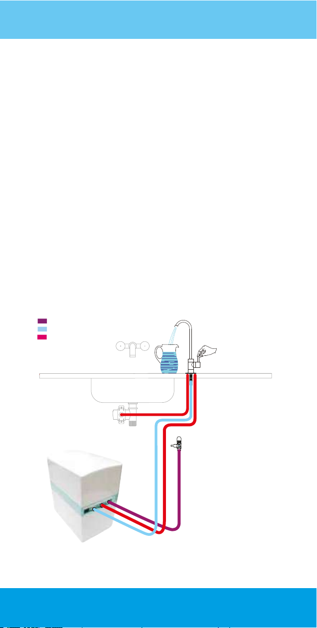
Installation diagram for the appliance is shown in Figure 4.
RO System contains critical components
9
Page 10
! Warning
1- Measures should be taken against freezing.
2- Waste water should not interfered with.
3- When muddy (clay) water comes from the mains, close the
water inlet of the appliance.
4- If a water supply other than the mains will be used, you must
receive a drinking water report from relevant institutions.
5- If it is a water source other than the mains water, make sure
that the disinfection process is performed.
6- Filters are considered as supplies and areoutside the scope
of warranty.
City Water
RO Water
Waste Water
7
6
2
1- Aura Cebilon Plus RO System
2- Water inlet valve
1
3
4
5
3- Water inlet
4- Waste water outlet
5- RO water outlet (Fresh water)
6- Waste water clamp
7- Tap
Figure 4. RO Installation diagram
10
Page 11
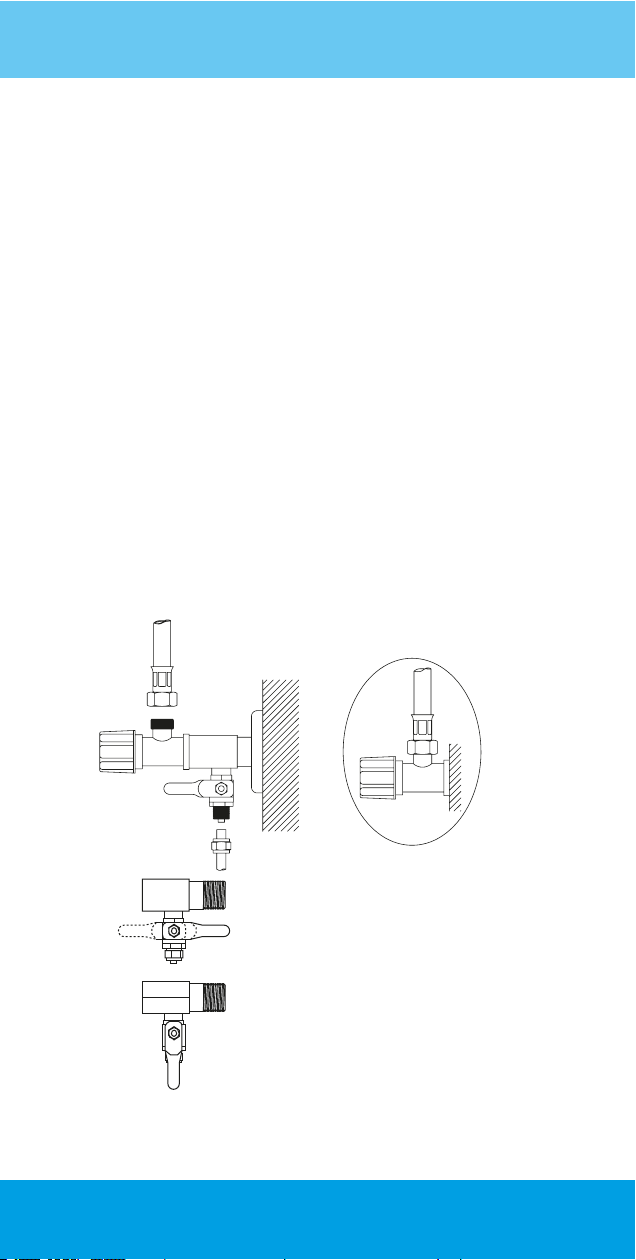
Water Connection
• Close the mains water from the apartment inlet valve.
• After draining the water left in the pipes from proper places, mount
the three-way adapter to the mains by ensuring the sealing.
• First, mount the 1/4 ball valve to the three-way adapter by wrapping
a teon tape in a position so that the valve is opened and closed
easily (Figure 5.a).
• Connect the water inlet hose to the ball valve (Figure 5.b).
• Make sure the ball valve is closed (Figure 5.c).
• Open the mains water, check whether there is any leakage (Figure 5.d).
• Place the appliance on a suitable place underneath the counter in
upright position.
a
c
d
Figure 5. Water connection ttings
b
11
Page 12
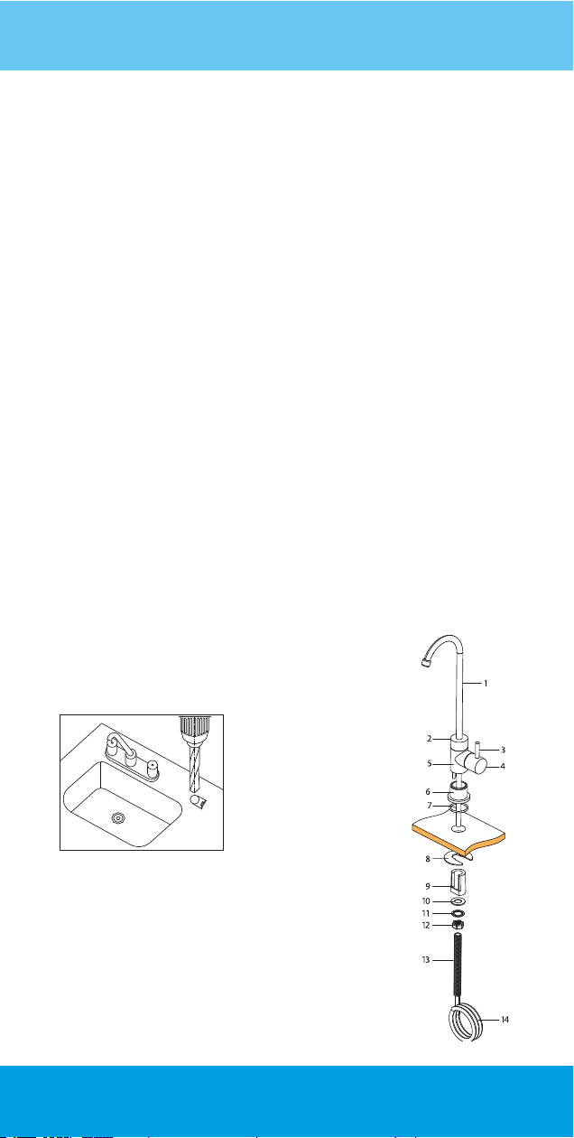
Installing a faucet
Clean water faucet should be mounted carefully in terms of use and
aesthetics. If the counter or kitchen sink will be drilled, drilling process
should be proceeded after the dimensions are obtained so as to install
the washers, nuts and unions under the counteror kitchen sink (Figure 6).
Otherwise, drilling may be incorrect.
The location to be drilled may be granite, marble, concrete or stainless
sink. If the counter is granite, it must be drilled with a 20 mm diameter
bore bit. Bore bit is attached to the end of the drill and it is set to low
speed. Water is poured on the ground to be drilled (do not drill without
water). Bend the bore bit as 45 degrees and press slightly, it makes a
trail on the granite. Then it is brought to an upright position slowly
without lifting. When it reaches the upright position, drilling is completed
by applying enough force. If the bore bit is not kept constant when we
start drilling, parts can break o from the granite surface. The o-ring on the
faucet's mirror cannot ensure sealing and may cause the water leakage
down from the counter. Marble countertops can be drilled by the same
drilling bit or bore bit. Concrete countertops are drilled with a contact tip
and hammer drill. If concrete is coated with tiles, a pre drill is made with a
small-diameter drill bit to avoid cracking the tiles. Bore bit for the stainless
sinks is dierent.
The hose should be mounted carefully between the faucet mounted on the
counter and on the appliance where "Clean Water" is written.
Water connection ttings
1 Faucet Pipe
2 Upper Body Part
3 Opening/Closing Handle
4 Hub Cover
5 Faucet Body
6 Body Bushing
7 Body Bushing O-ring
8 Mounting Parts
9 Mounting Plastic
10 Plastic Mounting Washer
11 Crinkled Spring Washer
12 Compression Nut
13 Faucet Screw
14 1/4” Hose
12
Figure 6. Faucet
Page 13
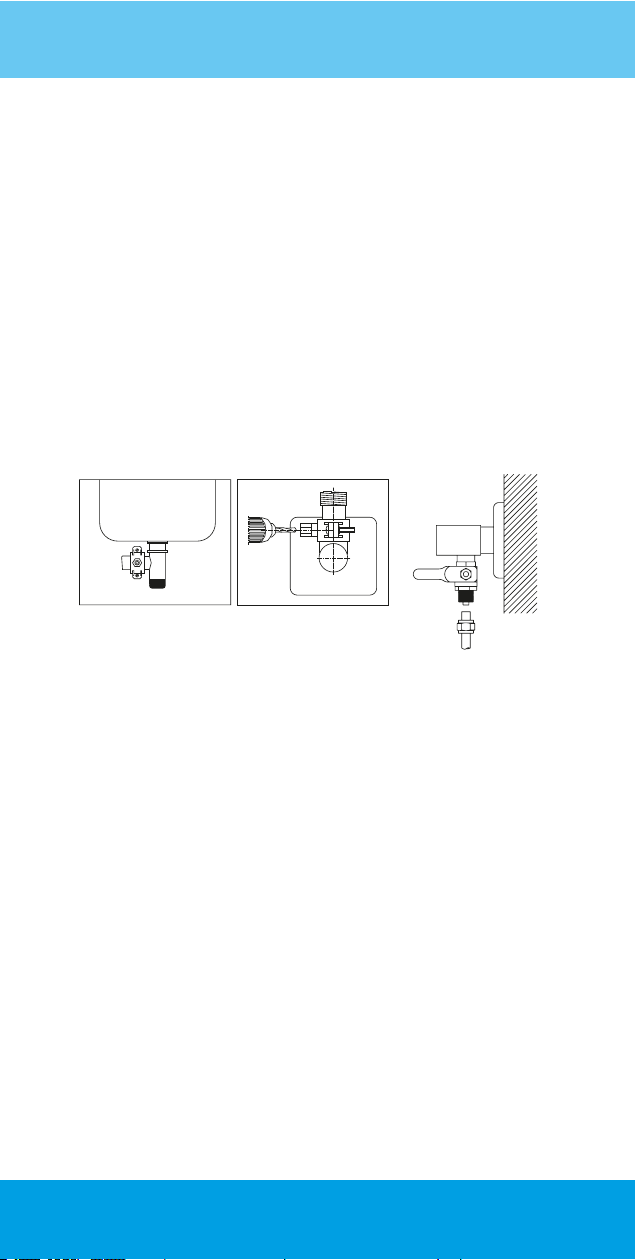
Waste Water Connection
• If waste water pipe of the sink is not a throat hose but a 40 mm
plastic pipe, it is mounted in a 3/8" clamp sealing sponge axed
state (Figure 7a).
• The ush is drilled from the hole of the clamp in 8 mm diameter
on the same axis (Figure 7b). One end of the 3/8" waste water
faucet is connected to this clamp and the other end is connected
to the 3/8" waste water union.
• If waste water hose will be mounted on the 50 mm waste water
installation, 3/8" clamp will be mounted and the waste water
a hose will be mounted on its location above this. A seal must be
used when mounting the adapter to the waste water installation.
Figure 7. Waste water connectiona b
Figure 8. Mains inlet valve
Pre-tests
• Adapter is plugged in after the adapter jack is inserted into the 24 V DC
power inlet on the appliance.*
• Fresh water tap is open .
• Tank valve should be closed.
• Opening up the ¼” ball valve, mains water is supplied to the system
(Figure 8.). Pump starts to operate.
• When amount of water ow took place, tap is closed
• Once the operation of the pump is stopped, leakage control is performed
in each and every connection, tank valve is opened up.
• Since the tank will be lled for the rst time, tank water is let to ow for no
purpose, for at least once. The appliance is now ready to use
• This system should be used after the twenty-four hours washing process,
(Installation is done after this process is carried out by an authorized service.)
* Only available in 101MF model.
Points for Attention
• The appliance is designed for domestic use. Parts such as storage
tank, waste water hose, faucet must be attached indoor environment.
Necessary measures should be taken to prevent freezing and waste
water ow.
13
Page 14

• Use the appliance after the necessary measures are taken in
microbiologically unsafe or disinfected waters.
• The appliance must be supplied with its own power adapter. *
• If the appliance will not be used for a long time (such as more than
1 month), the inlet water valve must be closed , the tank should be
drained and the adapter should be plugged out and the authorizes
service must be called to disinfect the appliance when reactivating.
• When there not anyone in the house, close the water inlet valve of
the appliance for safety purposes (Figure 8).
• The appliance must not be interfered for repair and maintenance
purposes. Otherwise, it falls out of the warranty scope, these
operations are carried out by
Aura Cebilon Plus
Authorized Service.
Filter Flushing and Conditioning
Procedures
• The rst three lters shall be ushed separately. Firstly close the ball
valve that supplies mains water to the system. Remove the outlet tube
on the housing cover of rst lter. Insert one meter ¼ Inch tube to the
outlet of the cover. And then open the ball valve, ush the lter for 2-3
minutes with mains water. Insert the outlet tube to its place and follow
the same procedure for the other two lters.
• After that when you ush membrane lter remove tubes on the
both outlets of the membrane housing. Insert one meter tube to the
both outlet. Flush the membrane for 2-3 minutes to clear membrane
form protective membrane solution.
• Install the tube that has ow restrictor on it but not to install the
tube that goes to post carbon lter.
• Allow water ow for 2-3 minutes to clear the membrane
solution completely. And then install the tube that goes to post
carbon lter.
• Then storage tank will be lled for the rst time, tank water is let to ow
for no purpose, for at least once. The appliance is now ready to use.
• When you ush lters, some water drops can cause E2 (water
leakage error). So dry the sensor and the device completely. Be careful
that there will be no water drop in the device somewhere. If you
experience such a problem, dry the sensor and device and then pull
out the plug and then install the plug again the E2 error will disappear.
• Also there are three pcs L elbow that is not installed to the
device. These elbows should be xed to the inlet and outlets of the
device for preventing tube breakage.
14
Page 15
• As the inlet water temperature changes, the amount of clean water
to be received and the eciency may change. Therefore, water
obtained may be low in winter and high in summer.
• In any unfavorableness (Figure 8) close the water inlet valve and
consult
Aura Cebilon Plus
Authorized Service.
* Only available in 101MF model.
Maintenance
Maintenance of your appliance must be performed by an
Cebilon Plus
The life of the lters used in
Authorized Service.
Aura Cebilon Plus
RO System changes
Aura
depending on various factors with the amount of water used. These
major factors are inlet water quality, chlorine amount, residue amount
etc. Filters are considered as supplies and they are out of warranty.
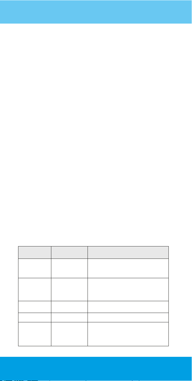
Recommended Filter
Replacement Periods
Have timely periodic maintenance of your appliance to use your
system eciently and for longer time. The following replacement
periods are the recommended durations for appliances used in
mains water under normal conditions.
The usage condition of your appliance may change depending
on the properties of inlet water, amount of chlorine and sediment.
Our authorized services will perform periodic maintenance
required for your system to work eciently every six months.
Replacement
Period
Sediment ltration is performed by taking coarse
5 Micron Sediment
Filter 340071Z
GAC Filtre
340069Z
1 Micron Sediment
Filter 340070Z
Mineral Carbon
Filter 340005Z06
Membrane
349004Z02
For the replacement parts please contact your local dealer or www.iea.com.tr / +90 212 875 35 62
6 months
6-12 months
6-12 months
2-5 years
particles in water. Clears the water at a micron
level. Its life varies depending on the nature of
the inlet water.
Keeps all the gas in water chemically in itself. The
excess chlorine reduces the life of the 1st carbon
lter (GAC). Timely replacement protects from
damage of chlorine and extends the life of the
membrane lter.
Sediment lter holds the carbon dust to keep from
plugging of membrane
Regulates the pH by supplying mineral to water. 6-12 months
This is where Reverse Osmosis occurs. Life of the
lter will change depending on the ion
concentration in the mains water, amount of the
distilled water and whether the maintenance is
carried out in a timely manner.
DutiesFilter Name
15
Page 16
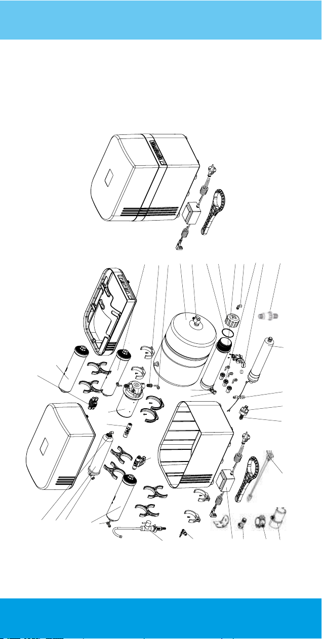
Aura Cebilon Plus Reverse Osmosis System
Part List
8
4
3
18
5
31
9
24
25
2
29
1
22
23
12
32
7
19
27
28
16
13
10
6
15
27
30
20
14
26
11
21
33
17
34
16
Page 17
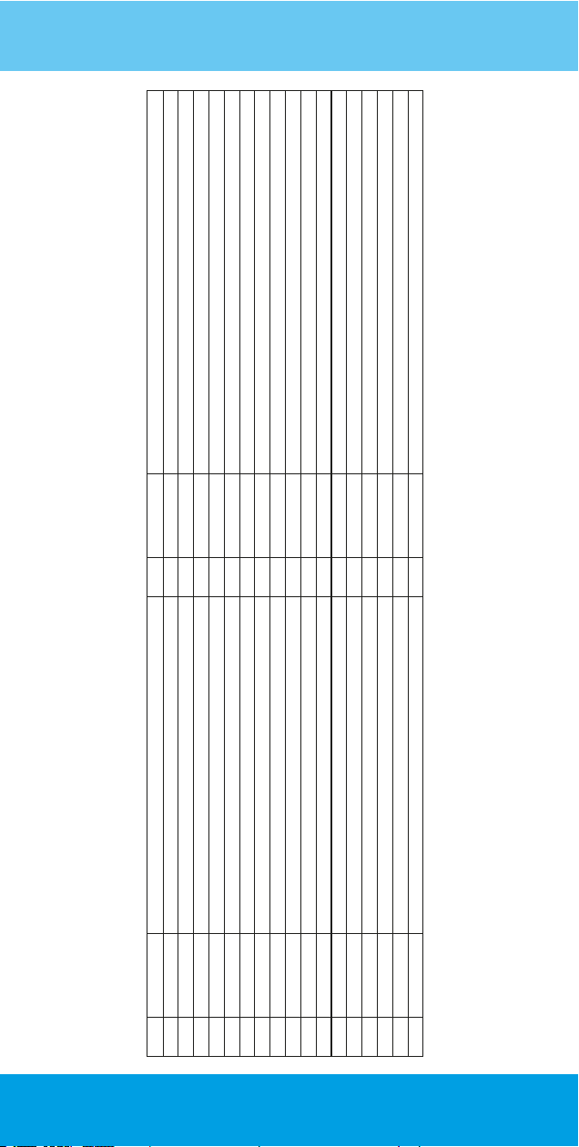
P. No Part Code Part Name P. No Part Code Part Name
Sediment Filter Group 5 Micron 12''
19 341003Z Plastic Tank Valve
Sediment Filter Group 1 Micron 12''
346003Z03
341067Z01
Cover,Membrane Housing
Oring (54X3,35) Membrane Housing
340005Z06
340059Z01 Flow Dedector (Leakage)
341088Z01 Low Pressure Body (In-Out)
341084Z02 High Pressure Switch Body
Transformer - 24V DC / 1,2A
349004Z02 Filmtec Membranes BW60-1812-75
Bulkhead Union, 1/4''ODx1/4''OD
17 343001Z Feed Water Connector Internal Thread (1/2''X1/4''X1/2'') 34 341125Z Waste Water Connecting Adaptor, 1/4"
3 340069Z GAC Filter Group 12'' 20 341130Z01 Pressure Regulator
1 350001Z Clean Water Tank 2,2G 18 340006Z04 Automatic Shut Off Valve
2 340071Z
21 341099Z QC Male Connector 1/4"ODx1/4"NPTF
24 341103Z QC Male Branch Tee 1/4'' OD X 1/4 NPT X 1/4'' OD
25 341100Z QC Male Elbow 1/4"ODx1/4"NPTF
27 341101Z QC Male Elbow 1/4'' OD X 1/8'' NPTF
28 341105Z Check Valve1/4 OD X1/8 NPT
29 341319Z QC Stem Branch Tee 1/4'' OD X 1/4'' OD X 1/4'' OD
30 343001Z01 Feed Water Connector Internal Thread - (1/2"x1/4"x1/2")
31 341106Z02 QC Flow Restrictor 300cc
32 343034Z Faucet
Pump 22 341141Z QC Male Connector 1/4"ODx3/8"NPTF
Membrane Housing 23 341307Z QC Stem Elbow 1/4''ODx1/4''OD
Post Carbon Filter 26 346029Z01 Cable Group with Socket
6
7 341068Z
4 340070Z
5
8 344004Z
9
10
11
12
13 356007Z
14
15 341048Z
16 343002Z Ball Valve (1/4''X1/4''') 33 346040Z Cable Group
17
Page 18
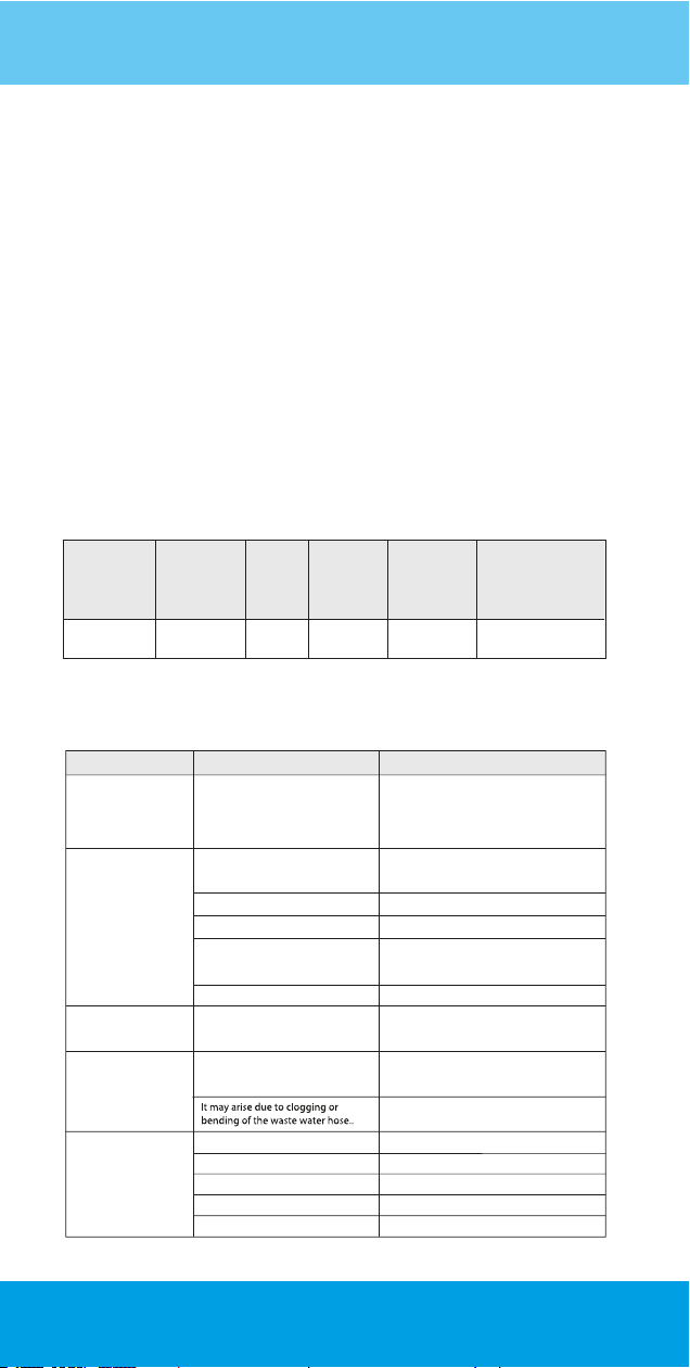
Performance Data Sheet
Cebilon Plus 101MF model system conform to NSF/ANSI 58 for the specific performance
claims as verified and substantiated b test data.
• Do not use this system with any water that is microbiologically unsafe, that does not
have adequate disinfection before or after operation or that of the quality is unknown.
• This System contains critical components that are required to be replaced periodically
to purify the total dissolved solid materials (TDS). To check the efficiency of the system,
water from the appliance must be tested periodically.
• Your appliance contains critical components that must be replaced periodically with
respect to the system's efficiency. These critical components must be replaced with
components and filters with the specifications defined by the manufacturer so that the
system can operate continuously with the same efficiency and performance.
• 101MF has been tested according to NSF/ANSI 58 for reduction of the substances
listed below. The concentration of the indicated substances in water entering the
system was reduced to a concentration less than or equal to the permissible limit for
water leaving the system, as specified in NSF/ANSI 58. Testing was performed under
standard laboratory conditions, actual performance vary.
Substance
Total dissolved
solids (TDS)
Inuent
Challenge
Concentration
750 ± 40 790
Average
Inuence
(mg/L)
Average
Euent
(mg/L)
34
Average
%
Reduction
95.7 187
Troubleshooting
Complaints Possible Causes Solution Recommended
There are bubbles n
water or water ows n
mlk color.
The applance gves
less water.
Although the tank s
full, water can not be
receved from the tap.
There s excessve nose
n the equpment.
Pump operates
constantly*
There s ar n the system.
Pump does not functon and there
s not sucent pressure.*
Pre-fltraton set s clogged.
Membrane does not functon properly.
The temperature of the nlet water
decreased.
Check valve s defectve.
Stock ar pressure of the tank s
nsucent.
Waste water hose may gve out water
ow sound.
Hgh Pressure Swtch may be defectve.
Low Pressure Swtch may be defectve.
Check valve may be defectve.
Shuto valve may be defectve.
Pump may be defectve.
* Only available in 101MF model.
Exstance of ar n the system just after the
frst nstallaton s normal. Sometmes, there
may be ar orgnatng from the mans. It wll
become normal after usng for a specfc
tme. Usng ths water s not harmful.
Check that the pump electrcal adapter s
plugged. If the adapter s plugged, contact
the servce.
Contact the servce
Contact the servce
Ths s not a falure. It s normal that amount
of fresh water decreases by a specfc
amount n wnter season.
Contact the servce
There s not ar remaned n requred amount
n the tank. Contact the servce.
Brng the poston of the clamp attached to
the sphon and the waste water hose passng
through t nto an approprate condton.
Clean the cloggng n the outlet hose or
straghten the bended hose.
Shut o the nlet water, contact the servce.
Shut o the nlet water, contact the servce.
Contact the servce.
Contact the servce.
Contact the servce.
Maximum
permissible product
water concentration
(mg/L)
18
Page 19
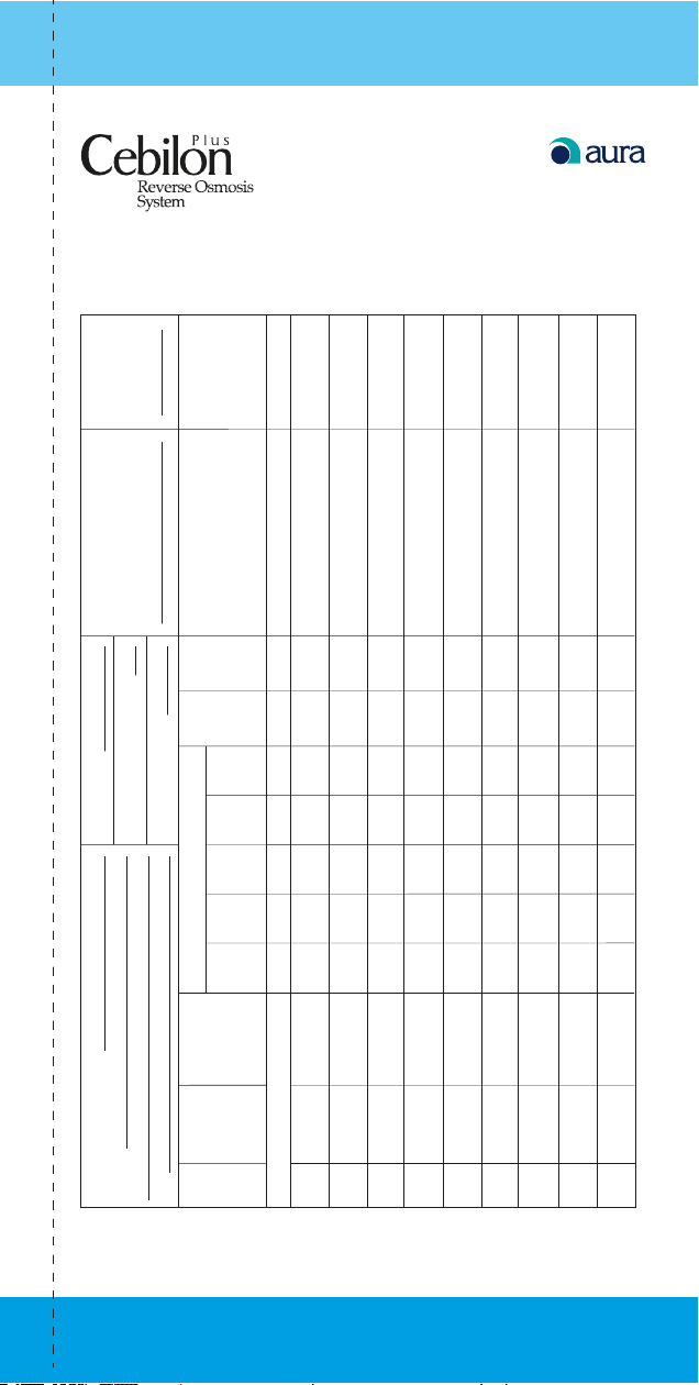
PRODUCT
SERIAL NO
SERVICE TELEPHONE
Intallation Date
Number of people in the family:
Mains Water TUS Value:
Maintenance Card
Service Personnel Name Surname Signature
lter
TDS After
replaciment
lter
TDS before
replaciment
Filter
Carbon
Mineral
Filter
Membran
Filter
Sediment
Filter
Replaced Filters
Carbon
Filter
Sediment
_ _ _ _ _ _
Date
Filter Replaciment
Recommended Next
First Installation
Serial No
Date Product
Filter Replaciment
1
2
Customers Name Surname:
Address:
No
Tel:
Order
3
THIS PAGE WILL TAKEN BY SERVICE TECHNICIAN
4
5
6
7
8
9
19
Page 20
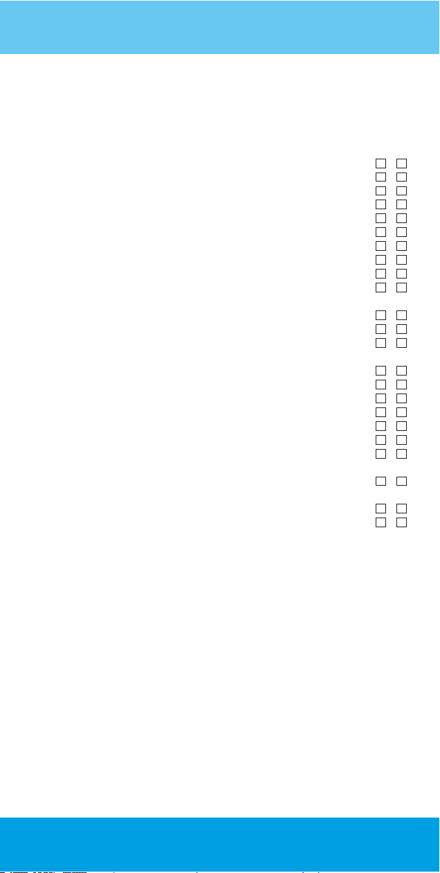
Checklist
Considerations to be Checked
S.No
1 Did you measure the chloride amount present in mains water?
2 Did you measure the hardness of mains water?
3 Did you measure the TDS value in mains water?
4 Did you measure the pressure in mains water?
5 Is the pressure of the tank appropriate?
6 Did you ask customer the appropriate place for installation?
7 Have connections of 3-way adapter been sealed?
8 Did you ask customer the installation place of tab?
9 Is the drilling set appropriate for the material used in the counter?
10 Does the appliance have an appropriate plug for the adapter of the
appliance?*
11 Did you check the chloride amount at the membrane inlet after installation?
12 Did you check fresh water / waste water ratio?
13 Did you adjust the waste water ratio in accordance with the hardness of
mains water?
14 Did you check the automatic shuto valve?
15 Did you check that low pressure switch actuates the pump?*
16 Did you check that low pressure switch stopped the pump?*
17 Did you check that high pressure switch stopped the pump?*
18 Did you perform a leakage check?
19 While performing those actions, did you actuate the pump of the appliance?*
20 Has the connection of the waste water hose to the outlet been made
appropriately?
21 Has the client been informed that he/she has to drain a tank water for no
purpose?
22 Has the maintenance card been processed?
23 Has the client been given the necessary explanations?
Yes No
* Only available in 101MF model.
Service Personel : .................................................................................................................................................................
Installation Date : .................................................................................................................................................................
Appliance Serial Number : ......................................................................................................................
20
Page 21
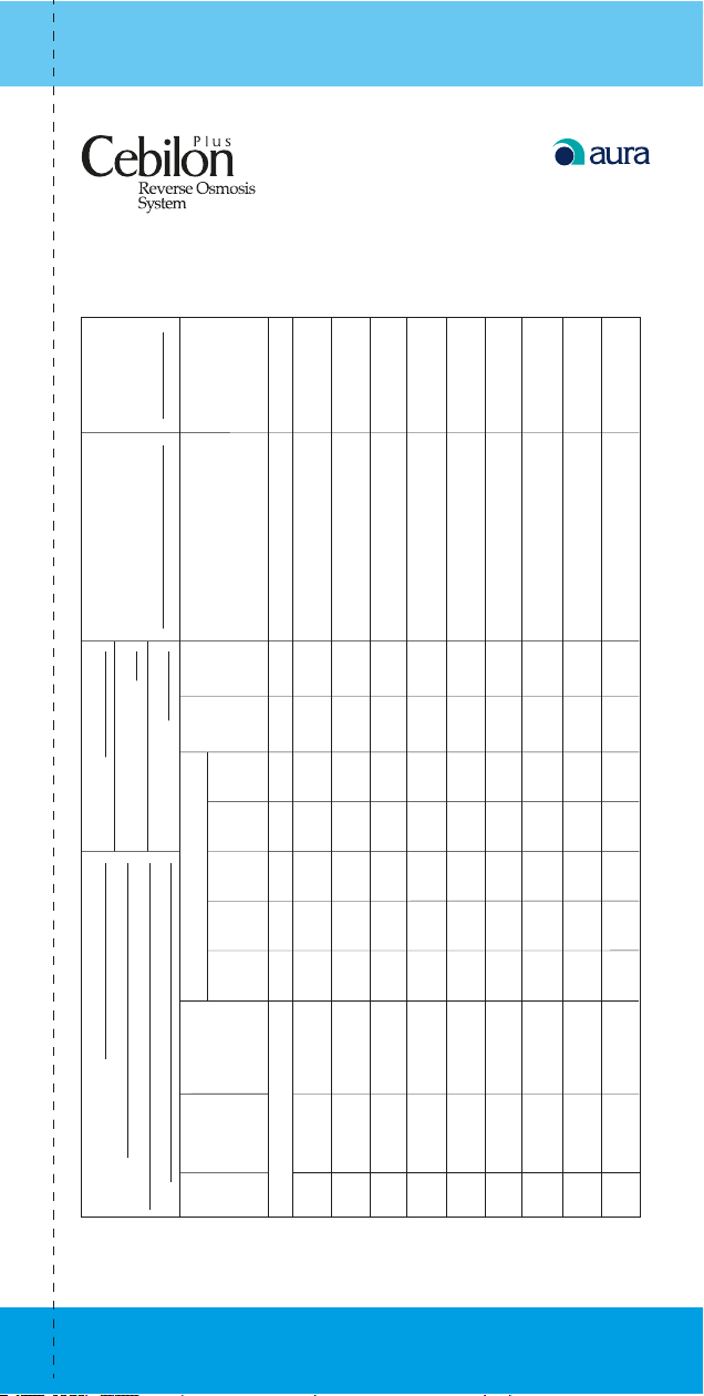
PRODUCT
SERIAL NO
SERVICE TELEPHONE
Intallation Date
Number of people in the family:
Mains Water TUS Value:
Maintenance Card
Service Personnel Name Surname Signature
lter
TDS After
replaciment
lter
TDS before
replaciment
Filter
Carbon
Mineral
Filter
Membran
Filter
Sediment
Filter
Replaced Filters
Carbon
Filter
Sediment
_ _ _ _ _ _
Customers Name Surname:
Address:
Date
Filter Replaciment
Recommended Next
First Installation
Serial No
Date Product
Filter Replaciment
1
2
3
4
5
6
7
8
No
Tel:
Order
9
21
Page 22
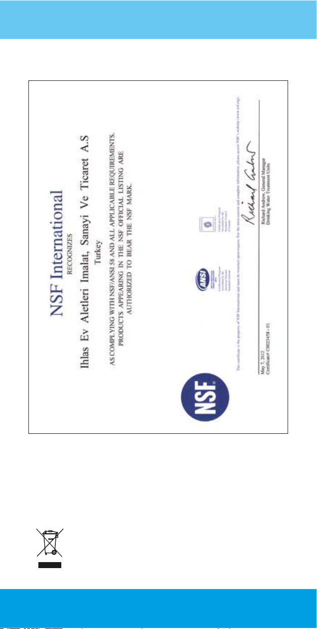
Complies with WEEE Regulation.
This symbol on the product or packaging shows that the product
should not be disposed of withnormal domestic waste and should
be transmitted to the collection points for recycling theelectrical
and electronic appliances. If you dispose of this product correctly,
you will be contributingto the protection of the nature and human
health. Wrong disposal will be harmful to the nature andhuman
health. You may nd further information on recycling this product
from your municipal, waste collection service or from the store you
have purchased the appliance.
Page 23

Warranty Certif icate
AURA CEBILON PLUS OWNER’S
Name Surname
Phone Number
Address
Purchase Date
.....................................................................................................................................................................................................................................................................
.....................................................................................................................................................................................................................................................................
.....................................................................................................................................................................................................................................................................
.....................................................................................................................................................................................................................................................................
AURA CEBILON PLUS’S
Appliance Serial Number
Date of Invoice
Invoice No
...............................................................................................................................................................................................................................................
.....................................................................................................................................................................................................................................................................
.....................................................................................................................................................................................................................................................................
AURA CEBILON PLUS DISTRIBUTOR’S
Company Name
Address
Phone Number
Other Information
.....................................................................................................................................................................................................................................................................
.....................................................................................................................................................................................................................................................................
.....................................................................................................................................................................................................................................................................
.....................................................................................................................................................................................................................................................................
AURA CEBILON PLUS SALES REPRESANTATIVE’S
Name Surname
Phone Number
Signature
Warranty Conditions
This product is manufactured for global distribution and sales.
Since the warranty conditions and periods of this type of product varies from country to country, please
contact your reginal distributor or seller for information concerning the applicable warranty and service
policies. Please make sure you understand clearly the policies and procedures concerning the warranty. It
is solely the distributor’s responsibility to set up a warranty policy in compliance with the local laws and
regulations. Please report your comments and complaints to the distibutor or to the manufacturer and report
your satisfaction and happiness to your friends as recommendation to them to know more about the
excellence of Aura Cebilon Plus.
.....................................................................................................................................................................................................................................................................
.....................................................................................................................................................................................................................................................................
Page 24

BOSB Mermerciler Sanayi Sitesi 7. Cad. No:14
34524 Beylikdüzü / İSTANBUL
Tel: +90 212 875 35 62, Faks:+90 212 875 36 64
www.iea.com.tr - [email protected]
348115ZEN
 Loading...