

Page 1

AUO
) Preliminary Specifications
(
( V ) Final Specifications
Product Specification
AU OPTRONICS CORPORATION
Module
Model Name
Note ( )
Customer Date
Checked &
Approved by
13.3” WXGA Color TFT-LCD
B133EW04 V1
LED Backlight without
driving circuit design
www.jxlcd.com
www.jxlcd.com
Date
Approved by Date
Howard Lee 11/19/2008
Prepared by Date
Note: This Specification is subject to change
without notice.
NBBU spec. Template 1.0
Johnson Kuo 11/19/2008
NBBU Marketing Division /
AU Optronics corporation
1 of 32
Page 2

Product Specification
AUO
AU OPTRONICS CORPORATION
Contents
1. Handling Precautions .............................................................. 4
2. General Description ................................................................ 5
2.1 General Specification ..........................................................................................................................5
2.2 Optical Characteristics ........................................................................................................................6
3. Functional Block Diagram ....................................................... 8
4. Absolute Maximum Ratings..................................................... 9
4.1 Absolute Ratings of TFT LCD Module...............................................................................................9
4.2 Absolute Ratings of Backlight Unit.....................................................................................................9
4.3 Absolute Ratings of Environment .......................................................................................................9
5. Electrical characteristics ....................................................... 10
5.1 TFT LCD Module..............................................................................................................................10
5.2 Backlight Unit ...................................................................................................................................12
6. Signal Characteristic ............................................................. 13
6.1 Pixel Format Image ...........................................................................................................................13
6.2 The input data format ........................................................................................................................14
6.3 Signal Description/Pin Assignment...................................................................................................15
6.4 Interface Timing ................................................................................................................................16
7. Connector Description........................................................... 19
7.1 TFT LCD Module..............................................................................................................................19
www.jxlcd.com
8. Dynamic Test ........................................................................ 20
8.1 Vibration Test ....................................................................................................................................20
8.2 Shock Test Spec:................................................................................................................................20
www.jxlcd.com
9. Reliability.............................................................................. 21
10. Mechanical Characteristics.................................................. 22
10.1 LCM Outline Dimension.................................................................................................................22
11. Shipping and Package ......................................................... 26
11.1 Shipping Label Format ....................................................................................................................26
11.2 Carton package ................................................................................................................................27
11.3 Shipping package of palletizing sequence.......................................................................................27
12. Appendix: EDID description ................................................ 29
NBBU spec. Template 1.0
2 of 32
Page 3
Product Specification
AUO
AU OPTRONICS CORPORATION
Record of Revision
Version and Date Page
0.1 2008/08/29 All First Edition for Customer
www.jxlcd.com
www.jxlcd.com
Old description New Description Remark
NBBU spec. Template 1.0
3 of 32
Page 4

Product Specification
AUO
1. Handling Precautions
1) Since front polarizer is easily damaged, pay attention not to scratch it.
2) Be sure to turn off power supply when inserting or disconnecting from input connector.
3) Wipe off water drop immediately. Long contact with water may cause discoloration or
spots.
4) When the panel surface is soiled, wipe it with absorbent cotton or other soft cloth.
5) Since the panel is made of glass, it may break or crack if dropped or bumped on hard
surface.
6) Since CMOS LSI is used in this module, take care of static electricity and insure
human earth when handling.
7) Do not open nor modify the Module Assembly.
8) Do not press the reflector sheet at the back of the module to any directions.
9) In case if a Module has to be put back into the packing container slot after once it was
taken out from the container, do not press the center of the LED lamp Reflector edge.
AU OPTRONICS CORPORATION
Instead, press at the far ends of the LED lamp Reflector edge softly. Otherwise the
TFT Module may be damaged.
10) At the insertion or removal of the Signal Interface Connector, be sure not to rotate nor
tilt the Interface Connector of the TFT Module.
11) After installation of the TFT Module into an enclosure (Notebook PC Bezel, for
example), do not twist nor bend the TFT Module even momentary. At designing the
enclosure, it should be taken into consideration that no bending/twisting forces are
applied to the TFT Module from outside. Otherwise the TFT Module may be damaged.
12)
Small amount of materials having no flammability grade is used in the LCD module. The
LCD module should be supplied by power complied with requirements of Limited Power
Source (IEC60950 or UL1950), or be applied exemption.
13)
Disconnecting power supply before handling LCD modules, it can prevent electric shock,
DO NOT TOUCH the electrode parts, cables, connectors and LED circuit part of
that a LED light bar build in as a light source of back light unit. It can prevent electrostic
breakdown.
www.jxlcd.com
www.jxlcd.com
TFT module
NBBU spec. Template 1.0
4 of 32
Page 5
Product Specification
AUO
2. General Description
B133EW04 V1 is a Color Active Matrix Liquid Crystal Display composed of a TFT LCD panel, a
driver circuit, and backlight system. The screen format is intended to support the WXGA
(1280(H) x 800(V)) screen and 262k colors (RGB 6-bits data driver) without backlight inverter.
All input signals are LVDS interface compatible.
B133EW04 V1 is designed for a display unit of notebook style personal computer and industrial
machine.
AU OPTRONICS CORPORATION
2.1 General Specification
The following items are characteristics summary on the table at 25 ℃ condition:
Items Unit Specifications
Screen Diagonal [mm] 337.8 (13.3W”)
Active Area [mm] 286.08 (H) X 178.8 (V)
Pixels H x V 1280x3(RGB) x 800
Pixel Pitch [mm] 0.2235 x 0.2235
Pixel Format R.G.B. Vertical Stripe
Display Mode Normally White
White Luminance
Note: I
Luminance Uniformity % 50 max. (160 points)
Contrast Ratio 500 typ, 400min
LED
www.jxlcd.com
www.jxlcd.com
is lamp current
[cd/m2] 275 typ @ 95% duty cycle
248 min @ 95% duty cycle
Response Time [ms] 16 typ, 25 max
Nominal Input Voltage
Power Consumption [Watt] 4.3 W @ Black ( typical)
Weight
Physical Size
Electrical Interface one channel LVDS
Surface Treatment Glare, Hardness 3H,
NBBU spec. Template 1.0
[Volt] +3.3 typ.
[Grams
[mm]
300(typical), 310 (max.)
L W T
Max 3.6
Typical 297.15 203.15 -
Min -
5 of 32
Page 6
Product Specification
AUO
RoHS Compliance
Support Color 262K colors ( RGB 6-bit )
AU OPTRONICS CORPORATION
Temperature Range
Operating
Storage (Non-Operating)
RoHS Compliance
[oC]
[oC]
0 to +50
-25 to +65
2.2 Optical Characteristics
The optical characteristics are measured under stable conditions at 25℃ (Room Temperature) :
Item Unit Conditions Min. Typ. Max. Note
White Luminance
Viewing Angle
Luminance
Uniformity
CR: Contrast Ratio
Cross talk %
Response Time [msec] Rising + Falling
Chromaticity of color
Coordinates
(CIE 1931)
NTSC
NTSC
NTSCNTSC
www.jxlcd.com
www.jxlcd.com
[cd/m2]
[degree]
[degree]
[degree]
[degree]
%
Red x
%%%%
Green x
160 points average 248 275 -
50/50
Right/left
Up
Down
160 point
400 500 - 1,2,3
Optical 2.0 1,2,3
Red y
Green y
Blue x
Blue y
White x
White y
CIE 1931
40/40
15
30
50 - 1,2
0.575 0.595 0.615
0.325 0.345 0.365
0.300 0.320 0.340
0.535 0.555 0.575
0.135 0.155 0.175
0.125 0.145 0.165
0.297 0.313 0.329
0.313 0.329 0.345
50/50
50/5050/50
25
35
- 16 25
- 45 -
1,2,3
-
-
1,2,3
-
-
1,2,3
NBBU spec. Template 1.0
6 of 32
Page 7

Product Specification
AUO
AU OPTRONICS CORPORATION
Note 1: The testing conditions are specified in 2.3
Note 2: The definitions of optical characteristics are shown in 2.4
Note 3: Measured at center point. Equivalent performance over the entire panel required
Note 4: Both center point and average of 160 points
www.jxlcd.com
www.jxlcd.com
NBBU spec. Template 1.0
7 of 32
Page 8
Product Specification
AUO
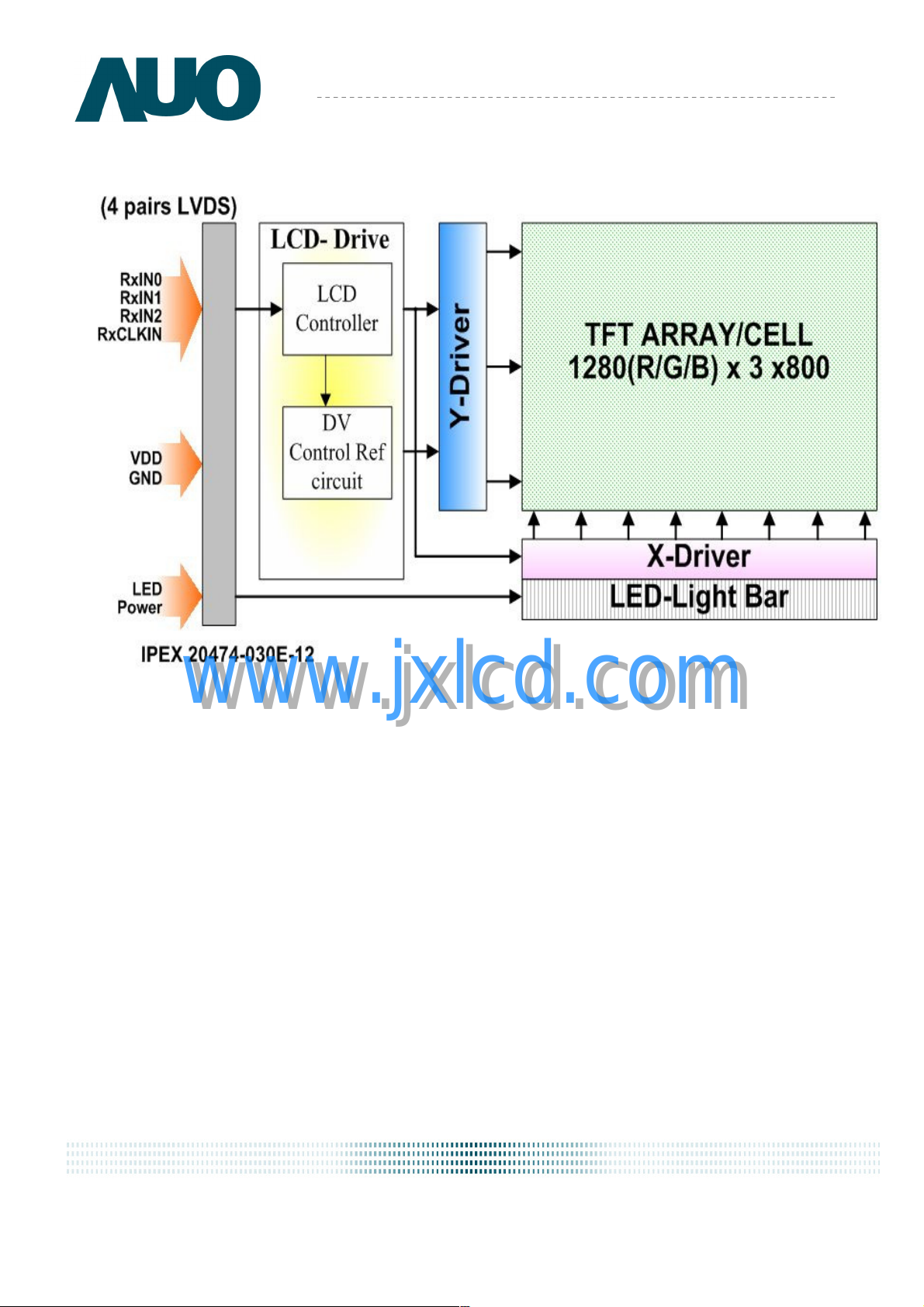
3. Functional Block Diagram
The following diagram shows the functional block of the 13.3 inches wide Color TFT/LCD Module:
AU OPTRONICS CORPORATION
www.jxlcd.com
www.jxlcd.com
NBBU spec. Template 1.0
8 of 32
Page 9
Product Specification
AUO
4. Absolute Maximum Ratings
An absolute maximum rating of the module is as following:
4.1 Absolute Ratings of TFT LCD Module
Item Symbol Min Max Unit Conditions
AU OPTRONICS CORPORATION
Logic/LCD Drive Voltage
Vin -0.3 +4.0 [Volt] Note 1,2
4.2 Absolute Ratings of Backlight Unit
Item Symbol Min Max Unit Conditions
LED Current ILED - 35 [mA] rms Note 1,2
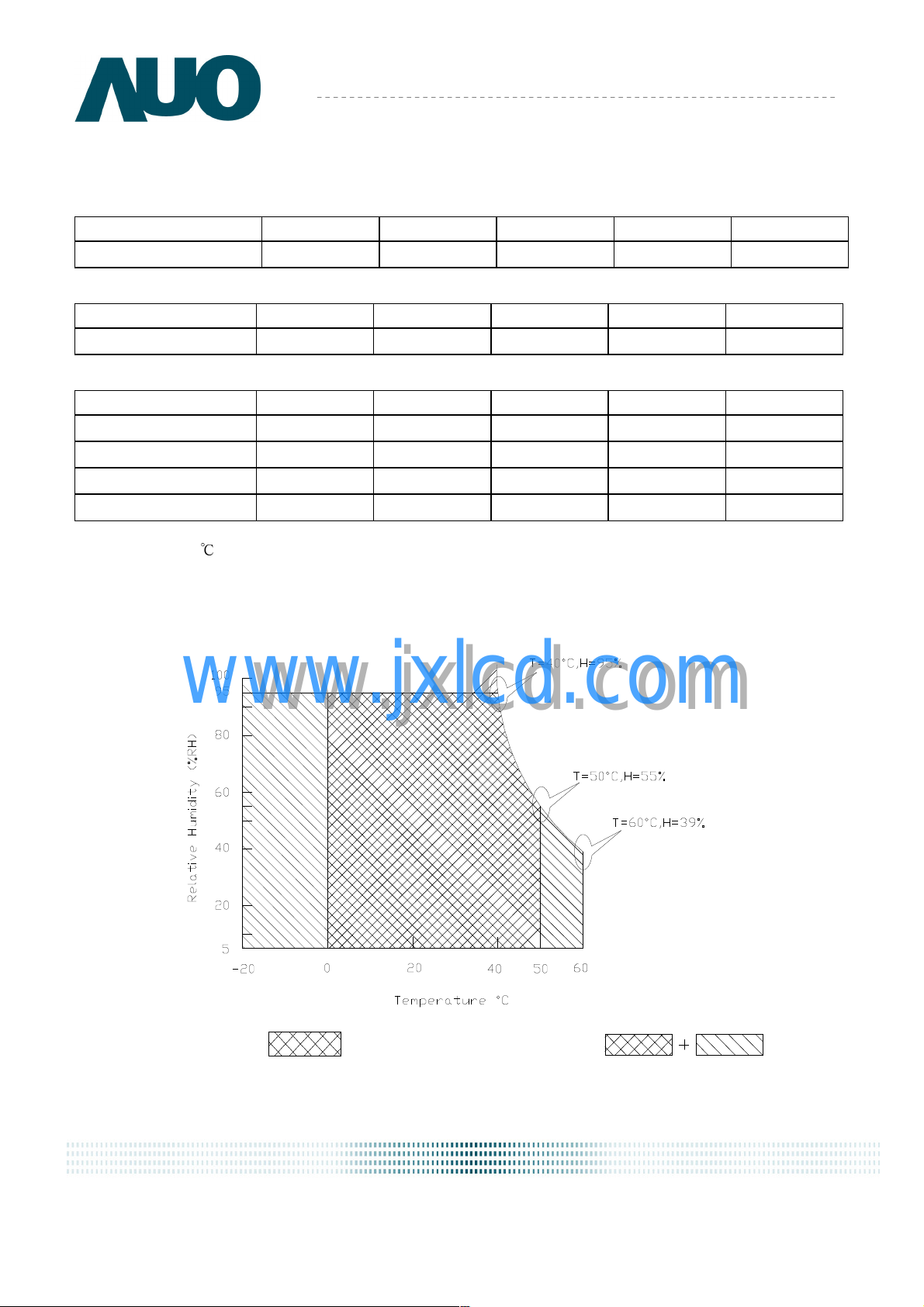
4.3 Absolute Ratings of Environment
Item Symbol Min Max Unit Conditions
Operating Temperature
Operation Humidity HOP 5 95 [%RH] Note 3
Storage Temperature
Storage Humidity HST
Note 1: At Ta (25℃ )
Note 2: Permanent damage to the device may occur if exceed maximum values
Note 3: For quality performance, please refer to AUO IIS (Incoming Inspection Standard).
www.jxlcd.com
www.jxlcd.com
TOP 0 +50 [oC] Note 3
TST -20 +60 [oC] Note 3
5 95
Twb=39°C
[%RH]
Note 3
Operating Range
NBBU spec. Template 1.0
Storage Range
9 of 32
Page 10

Product Specification
AUO
-
90%
10%
5. Electrical characteristics
5.1 TFT LCD Module
5.1.1 Power Specification
Input power specifications are as follows;
AU OPTRONICS CORPORATION
Symble Parameter Min Typ Max Units
VDD Logic/LCD Drive
PDD VDD Power
IDD IDD Current
I
Rush
Inrush Current
VDDrp Allowable
Logic/LCD Drive
Ripple Voltage
Note 1 : Maximum Measurement Condition:Black Pattern
Note 2:Typical Measurement Condition: Mosaic Pattern
Note 3:Measure Condition
www.jxlcd.com
www.jxlcd.com
3.0 3.3 3.6 [Volt]
0.9 [Watt] Note 1/2
- 220
- 0.7
- -
250
1.5
100
[mA]
[A]
[mV]
p-p
Note
Note 1/2
Note 3
3.3V
0V
0.5ms
Vin rising time
NBBU spec. Template 1.0
10 of 32
Page 11

Product Specification
AUO
5.1.2 Signal Electrical Characteristics
Input signals shall be low or High-impedance state when VDD is off.
Signal electrical characteristics are as follows;
AU OPTRONICS CORPORATION
Parameter
Vth
Vtl
Vcm
Note: LVDS Signal Waveform
Differential Input High
Threshold (Vcm=+1.2V)
Differential Input Low
Threshold (Vcm=+1.2V)
Common Mode Voltage
www.jxlcd.com
www.jxlcd.com
Condition Min Max Unit
Differential Input
-
-100
0.8
+100
-
2.0
[mV]
[mV]
[V]
NBBU spec. Template 1.0
11 of 32
Page 12

Product Specification
AUO
5.2 Backlight Unit
Parameter guideline for LED
LED Parameter guideline for LED driving selection (Ref. Remark 1)
Parameter
Parameter Symbol
ParameterParameter
LED Forward Voltage VF 2.8 3.0 3.2 [Volt] (Ta=25℃)
LED Forward Current IF 20 30 [mA] (Ta=25℃)
LED Power consumption P
LED Life-Time\ N/A 10,000 - - Hour
Output PWM frequency F
Duty ratio @20kHZ -- 5 -- 100 %
Note 1: Calculator value for reference IF×VF =P
Note 2: The LED life-time define as the estimated time to 50% degradation of initial luminous
Note 3: Totally using 54 Led bins
AU OPTRONICS CORPORATION
Symbol Min
SymbolSymbol
LED
4 [Watt]
PWM
100 200 20K Hz
Min Typ
MinMin
Typ Max
TypTyp
Max Units
MaxMax
Units Condition
UnitsUnits
Condition
ConditionCondition
(Ta=25℃)
Note 1
(Ta=25℃)
IF=20 mA
Note 2
www.jxlcd.com
www.jxlcd.com
NBBU spec. Template 1.0
12 of 32
Page 13

Product Specification
AUO
6. Signal Characteristic
6.1 Pixel Format Image
Following figure shows the relationship of the input signals and LCD pixel format.
AU OPTRONICS CORPORATION
www.jxlcd.com
www.jxlcd.com
NBBU spec. Template 1.0
13 of 32
Page 14

Product Specification
AUO
6.2 The input data format
AU OPTRONICS CORPORATION
www.jxlcd.com
www.jxlcd.com
NBBU spec. Template 1.0
14 of 32
Page 15

Product Specification
AUO
6.3 Signal Description/Pin Assignment
LVDS is a differential signal technology for LCD interface and high speed data transfer device.
Pin Signal Description
1
2
3
4
5
6
7
8
9
10
GND
Vcc
V
analog
V
EDID
Vsync
Clk
DATA
Rin0-
Rin0+
GND
EDID
EDID
Power Supply (+3.3V)
Power Supply (+3.3V)
DDC Power +3.3V
Vsync
DDC Clock
DDC Data
Differential Data Input
Differential Data Input
Ground
AU OPTRONICS CORPORATION
Ground
11
12
13
14
15
16
17
18
19
20
21
22
23
24
25
26
Rin1-
Differential Data Input
Rin1+
Differential Data Input
GND
Ground
Rin2-
Differential Data Input
Rin2+
Differential Data Input
GND
Ground
Clkin-
www.jxlcd.com
www.jxlcd.com
Clkin+
GND
NC
Vdc
Vdc
NC
Vdc1
Vdc2
Vdc3
Differential Clock Input
Differential Clock Input
Ground
NC
LED Anode (~31V )
LED Anode (~31V )
NC
LED Cathode (Ground)
LED Cathode (Ground)
LED Cathode (Ground)
27
28
29
30
Vdc4
Vdc5
Vdc6
AGING
LED Cathode (Ground)
LED Cathode (Ground)
LED Cathode (Ground)
AGING
NBBU spec. Template 1.0
15 of 32
Page 16

Product Specification
AUO
6.4 Interface Timing
6.4.1 Timing Characteristics
Basically, interface timings should match the 1280x800 /60Hz manufacturing guide line timing.
AU OPTRONICS CORPORATION
www.jxlcd.com
www.jxlcd.com
NBBU spec. Template 1.0
16 of 32
Page 17

AUO
6.4.2 Timing diagram
Product Specification
AU OPTRONICS CORPORATION
www.jxlcd.com
www.jxlcd.com
NBBU spec. Template 1.0
17 of 32
Page 18

AUO
6.5 Power ON/OFF Sequence
AU OPTRONICS CORPORATION
Product Specification
www.jxlcd.com
www.jxlcd.com
NBBU spec. Template 1.0
18 of 32
Page 19

Product Specification
AUO
7. Connector Description
Physical interface is described as for the connector on module.
These connectors are capable of accommodating the following signals and will be following
components.
7.1 TFT LCD Module
AU OPTRONICS CORPORATION
Connector Name / Designation
Manufacturer I-PEX
Type / Part Number
Mating Housing/Part Number
www.jxlcd.com
www.jxlcd.com
For Signal Connector
I-PEX 20474-030E-12
I-PEX 20472-030T-10
NBBU spec. Template 1.0
19 of 32
Page 20

AUO
8. Dynamic Test
8.1 Vibration Test
8.2 Shock Test Spec:
Product Specification
AU OPTRONICS CORPORATION
www.jxlcd.com
www.jxlcd.com
NBBU spec. Template 1.0
20 of 32
Page 21

AUO
9. Reliability
Product Specification
AU OPTRONICS CORPORATION
www.jxlcd.com
www.jxlcd.com
NBBU spec. Template 1.0
21 of 32
Page 22

AUO
10. Mechanical Characteristics
10.1 LCM Outline Dimension
www.jxlcd.com
www.jxlcd.com
NBBU spec. Template 1.0
22 of 32
Page 23

AUO
www.jxlcd.com
www.jxlcd.com
NBBU spec. Template 1.0
23 of 32
Page 24

AUO
www.jxlcd.com
www.jxlcd.com
NBBU spec. Template 1.0
24 of 32
Page 25

AUO
www.jxlcd.com
www.jxlcd.com
NBBU spec. Template 1.0
25 of 32
Page 26

AUO
11. Shipping and Package
11.1 Shipping Label Format
11.1 Shipping Label Format
www.jxlcd.com
www.jxlcd.com
NBBU spec. Template 1.0
26 of 32
Page 27

AUO
11.2 Carton package
www.jxlcd.com
www.jxlcd.com
11.3 Shipping package of palletizing sequence
NBBU spec. Template 1.0
27 of 32
Page 28

AUO
www.jxlcd.com
www.jxlcd.com
NBBU spec. Template 1.0
28 of 32
Page 29

AUO
12. Appendix: EDID description
B133EW04 V1
Address
HEX
00
01
02
03
04
05
06
07
08
09
0A
0B
0C
0D
0E
0F
10
11
12
13
14
15
16
17
18
19
1A
1B
1C
1D
1E
1F
20
21
22
23
24
25
26
27
FUNCTION B133EW04
Header
Header
HeaderHeader
EISA Manuf. Code LSB
EISA Manuf. Code LSB
EISA Manuf. Code LSBEISA Manuf. Code LSB
Compressed ASCII
Compressed ASCII
Compressed ASCIICompressed ASCII
Product Code
Product Code
Product CodeProduct Code
hex, LSB first
hex, LSB first
hex, LSB firsthex, LSB first
32
32----bit ser #
bit ser #
3232
bit ser #bit ser #
Week of manufacture
Week of manufacture
Week of manufactureWeek of manufacture
Year of manufacture
Year of manufacture
Year of manufactureYear of manufacture
EDID Struct
EDID Structure Ver.
EDID StructEDID Struct
www.jxlcd.com
www.jxlcd.com
EDID revision #
EDID revision #
EDID revision #EDID revision #
Video input definition
Video input definition
Video input definitionVideo input definition
Max H image size
Max H image size
Max H image sizeMax H image size
Max V image size
Max V image size
Max V image sizeMax V image size
Display Gamma
Display Gamma
Display GammaDisplay Gamma
Feature support
Feature support
Feature supportFeature support
Red/
Red/green low bits
green low bits
Red/Red/
green low bitsgreen low bits
Blue/white low bits
Blue/white low bits
Blue/white low bitsBlue/white low bits
Red x/ high bits
Red x/ high bits
Red x/ high bitsRed x/ high bits
Red y
Red y
Red yRed y
Green x
Green x
Green xGreen x
Green y
Green y
Green yGreen y
Blue x
Blue x
Blue xBlue x
Blue y
Blue y
Blue yBlue y
White
White x
WhiteWhite
White y
White y
White yWhite y
Established timing 1
Established timing 1
Established timing 1Established timing 1
Established timing 2
Established timing 2
Established timing 2Established timing 2
Manufacturer's Timing
Manufacturer's Timing
Manufacturer's TimingManufacturer's Timing
Standard timing #1
Standard timing #1
Standard timing #1Standard timing #1
Value Value Note
HEX BIN DEC
00 00000000 0
FF 11111111 255
FF 11111111 255
FF 11111111 255
FF 11111111 255
FF 11111111 255
FF 11111111 255
00 00000000 0
06 00000110 6
10 00010000 16
8C 10001100 140
9C 10011100 156
01 00000001 1
01 00000001 1
01 00000001 1
01 00000001 1
05 00000101 5
12 00010010 18
ure Ver.
ure Ver.ure Ver.
x
x x
01 00000001 1
01 00000001 1
03 00000011 3
80 10000000 128
1D 00011101 29
12 00010010 18
78 01111000 120
0A 00001010 10
50 01010000 80
85 10000101 133
98 10011000 152
58 01011000 88
52 01010010 82
8E 10001110 142
26 00100110 38
25 00100101 37
50 01010000 80
54 01010100 84
00 00000000 0
00 00000000 0
00 00000000 0
01 00000001 1
NBBU spec. Template 1.0
29 of 32
Page 30

AUO
Standard timing #2
Standard timing #2
28
29
2A
2B
2C
2D
2E
2F
30
31
32
33
34
35
36
37
38
39
3A
3B
3C
3D
3E
3F
40
41
42
43
44
45
46
47
48
49
4A
4B
4C Version
4D Apple edid signature
4E Apple edid signature
4F
50
51 Panel features (No inverter)
Standard timing #2Standard timing #2
01 00000001 1
Standard timing #3
Standard timing #3
Standard timing #3Standard timing #3
01 00000001 1
Standard timing #4
Standard timing #4
Standard timing #4Standard timing #4
01 00000001 1
Standard timing #5
Standard timing #5
Standard timing #5Standard timing #5
01 00000001 1
Standard timing #6
Standard timing #6
Standard timing #6Standard timing #6
01 00000001 1
Standard timing #7
Standard timing #7
Standard timing #7Standard timing #7
01 00000001 1
Standard timing #8
Standard timing #8
Standard timing #8Standard timing #8
01 00000001 1
Pixel Clock/10,000 (LSB)
Pixel Clock/10,000 (LSB)
Pixel Clock/10,000 (LSB)Pixel Clock/10,000 (LSB)
Pixel Clock/10,000 (MSB)
Pixel Clock/10,000 (MSB)
Pixel Clock/10,000 (MSB)Pixel Clock/10,000 (MSB)
Horiz. Active pixels(Lower 8 bits)
Horiz.Blanking (Lower 8 bits) A0 10100000 143
Horiz. Active pixels:Horiz.
Blanking (Upper4:4 bits) 50 01010000 80
20 00100000 32
17 00010111 46
Vert. Active pixels:Vert. Blanking
(Upper4:4 bits) 30 00110000 48
30 00110000 48
www.jxlcd.com
www.jxlcd.com
20 00100000 32
Vert. Sync. Offset=xx lines, Sync
Width=xx lines
Horz. Ver. Sync/Width (upper 2
bits) 00 00000000 0
Hori. Image size (Lower 8 bits) 1E 00011110 30
Vert. Image size (Lower 8 bits) B3 10110011 179
Hori. Image size : Vert. Image size
(Upper 4 bits) 10 00010000 16
00 00000000 0
00 00000000 0
18 00011000 24
Detailed timing/monitor
Detailed timing/monitor
Detailed timing/monitorDetailed timing/monitor
descriptor #2
descriptor #2
descriptor #2descriptor #2
00 00000000 0
Link Type (LVDS Link,MSB
justified)
Pixel and link component
format (6-bit panel interface)
01 00000001 1
01 00000001 1
01 00000001 1
01 00000001 1
01 00000001 1
01 00000001 1
01 00000001 1
52 01010010 82
1C 00011100 28
00 00000000 0
36 00110110 54
00 00000000 0
00 00000000 0
01 00000001 1
00 00000000 0
06 00000110 6
10 00010000 16
20 00100000 32
00 00000000 0
00 00000000 0
NBBU spec. Template 1.0
30 of 32
Page 31

AUO
52
53
54
55
56
57
58
59
5A
5B
5C
5D
5E
5F
60
61
62
63
64
65
66
67
68
69
6A
6B
6C
6D
6E
6F
70
71
72
73
74
75
76
77
78
79
7A
7B
7C
7D
Detailed timing/monitor
Detailed timing/monitor
Detailed timing/monitorDetailed timing/monitor
descriptor #3
descriptor #3
descriptor #3descriptor #3
www.jxlcd.com
www.jxlcd.com
Detailed timing/monitor
Detailed timing/monitor
Detailed timing/monitorDetailed timing/monitor
descriptor #4
descriptor #4
descriptor #4descriptor #4
0A 00001010 10
20 00100000 32
00 00000000 0
FE 11111110 254
00 00000000 0
42 01000010 66 B
31 00110001 49 1
33 00110011 51 3
33 00110011 51 3
45 01000101 69 E
57 01010111 87 W
30 00110000 48 0
34 00110100 52 4
20 00100000 32
56 01010110 86 V
30 00110000 48 1
0A 00001010 10
20 00100000 32
00 00000000 0
FE 11111110 254
00 00000000 0
43 01000011 67 C
6F 01101111 111 o
6C 01101100 108 l
6F 01101111 111 o
72 01110010 114 r
20 00100000 32
4C 01001100 76 L
43 01000011 67 C
44 01000100 68 D
0A 00001010 10
20 00100000 32
20 00100000 32
00 00000000 0
00 00000000 0
00 00000000 0
00 00000000 0
00 00000000 0
00 00000000 0
00 00000000 0
00 00000000 0
00 00000000 0
00 00000000 0
20 00100000 32
ASCII Data String:B133EW04 V0
ASCII Data String:B133EW04 V0
ASCII Data String:B133EW04 V0ASCII Data String:B133EW04 V0
Monitor Name: Color LCD
Monitor Name: Color LCD
Monitor Name: Color LCDMonitor Name: Color LCD
NBBU spec. Template 1.0
31 of 32
Page 32

AUO
7E
7F
Extension Flag
Extension Flag
Extension FlagExtension Flag
Checksum
Checksum
ChecksumChecksum
00 00000000 0
28 00101110 40
www.jxlcd.com
www.jxlcd.com
NBBU spec. Template 1.0
32 of 32
 Loading...