

Page 1
Model Name: T650HVN03.0 SKD
Issue Date : 2013/5/28
(****)Preliminary Specifications
( )Final Specifications
Customer Signature Date AUO Date
Approved By
_________________________________
Note
Approval By PM Director
CP Wang
Reviewed By RD Director
Eugene CC Chen
Reviewed By Project Leader
Bear Syong
Prepared By PM
Fanfan Lee
Page 2

Contents
No
CONTENTS
RECORD OF REVISIONS
1 GENERAL DESCRIPTION
2 ABSOLUTE MAXIMUM RATINGS
3 ELECTRICAL SPECIFICATION
3-1 ELECTRIACL CHARACTERISTICS
3-2 INTERFACE CONNECTIONS
3-3 SIGNAL TIMING SPECIFICATION
3-4 SIGNAL TIMING WAVEFORM
3-5 COLOR INPUT DATA REFERENCE
3-6 POWER SEQUENCE
4 OPTICAL SPECIFICATION
5 OPEN CELL DRAWING
6 RELIABILITY TEST ITEMS
7 PACKING
7-1 DEFINITION OF LABEL
7-2 PACKING METHODS
7-3 PALLET AND SHIPMENT INFORMATION
8 PRECAUTION
8-1 MOUNTING PRECAUTIONS
8-2 OPERATING PRECAUTIONS
8-3 ELECTROSTATIC DISCHARGE CONTROL
8-4 PRECAUTIONS FOR STRONG LIGHT EXPOSURE
8-5 STORAGE
8-6 HANDLING PRECAUTIONS FOR PROTECT FILM
Page 3
Record of Revision
Version
0.0 2013/05/28 First release
Date Page Description
Page 4
1. General Description
This specification applies to the 65.0 inch Color TFT-LCD Module T650HVN03.0 This LCD module has a TFT
active matrix type liquid crystal panel 1,920x1,080 pixels, and diagonal size of 65.0 inch. This module supports
1,920x1,080 mode. Each pixel is divided into Red, Green and Blue sub-pixels or dots which are arranged in vertical
stripes. Gray scale or the brightness of the sub-pixel color is determined with a 8-bit gray scale signal for each dot.
The T650HVN03.0 has been designed to apply the 8-bit 2 channel LVDS interface method. It is intended to
support displays where high brightness, wide viewing angle, high color saturation, and high color depth are very
important.
* General Information
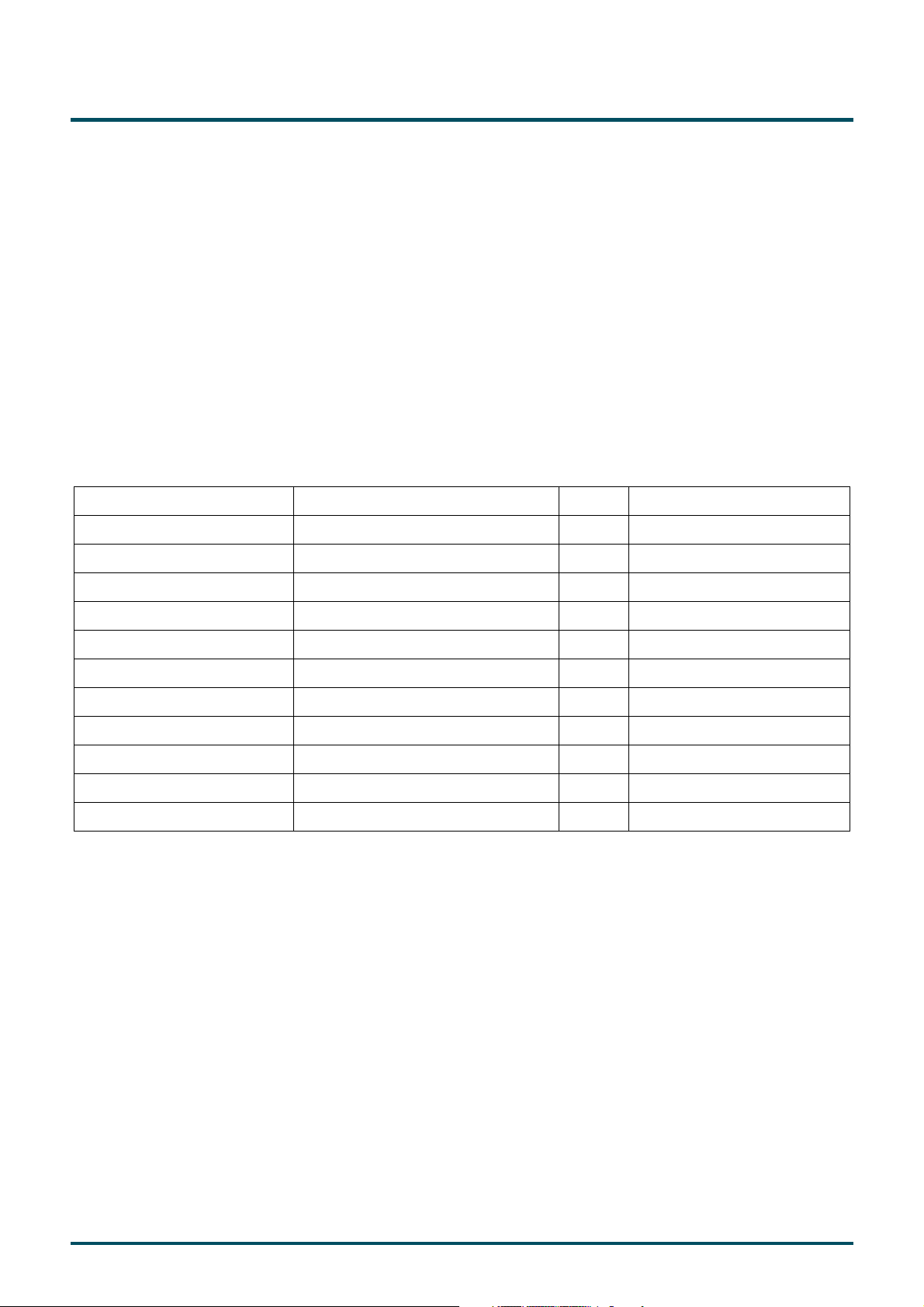
Items Specification Unit Note
Active Screen Size 65.00 inch
Display Area 1428.48 (H) x 803.52 (V) mm
Outline Dimension 1461.98 (H) x 839.24 (V) mm
Driver Element a-Si TFT active matrix
Display Colors 10 bit, 1073.7M Colors
Number of Pixels 1,920x1,080 Pixel
Pixel Pitch 0.744 (H) x 0.744 (W) mm
Pixel Arrangement RGB vertical stripe
Display Operation Mode Normally Black
Surface Treatment SC
Rotate Function Unachievable Note 1
Note 1: Rotate Function refers to LCD display could be able to rotate.
Page 5
2. Absolute Maximum Ratings
The followings are maximum values which, if exceeded, may cause faulty operation or damage to the unit
Item Symbol Min Max Unit Conditions
Logic/LCD Drive Voltage VDD -0.3 14 [Volt] Note 1
Input Voltage of Signal Vin -0.3 4 [Volt] Note 1
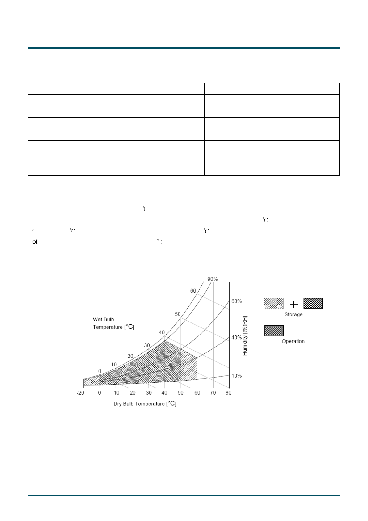
Operating Temperature TOP 0 +50 [oC] Note 2
Operating Humidity HOP 10 90 [%RH] Note 2
Storage Temperature TST -20 +60 [oC] Note 2
Storage Humidity HST 10 90 [%RH] Note 2
Panel Surface Temperature PST 65 [oC] Note 3
Note 1: Duration:50 msec.
Note 2 : Maximum Wet-Bulb should be 39 and No condensation.℃
The relative humidity must not exceed 90% non-condensing at temperatures of 40 or less. At temperatures
greater than 40 , the wet bulb temperature must not exceed 39 .
Note 3: Surface temperature is measured at 50℃ Dry condition
℃ ℃
℃
Page 6
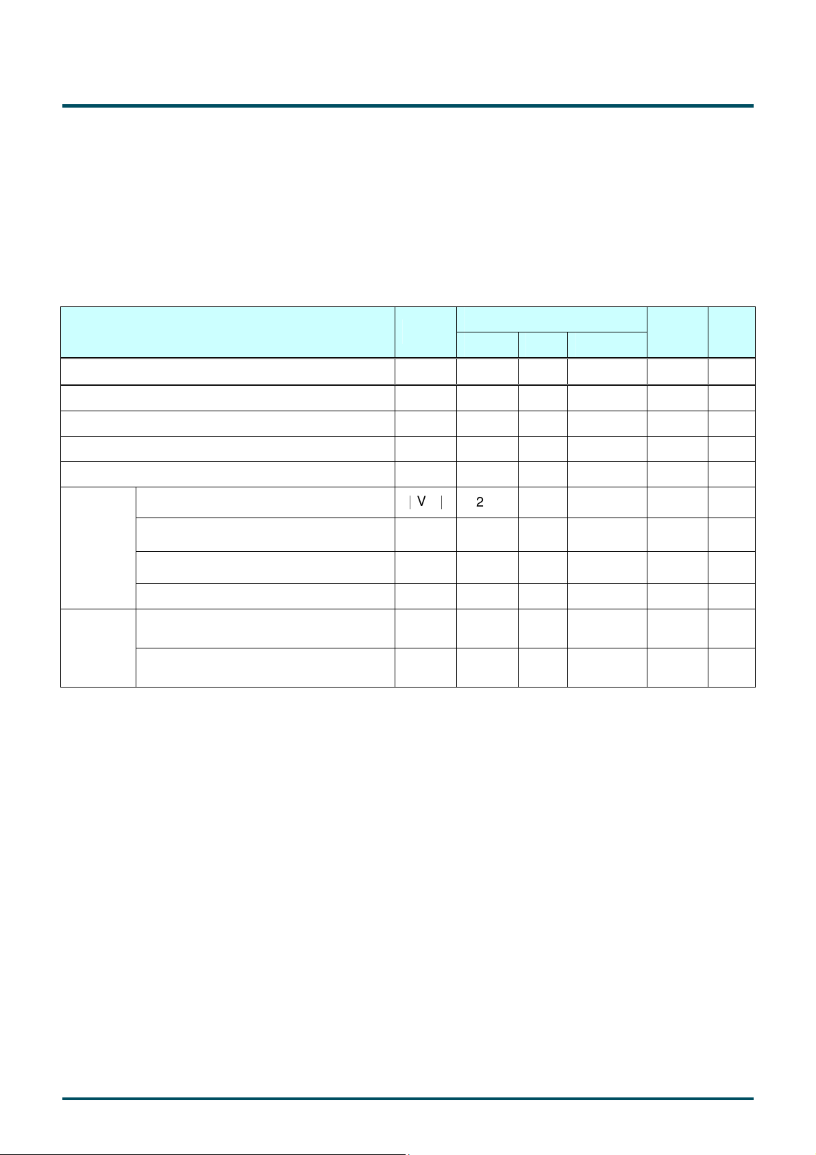
3. Electrical Specification
The T650HVN03.0 requires two power inputs. One is employed to power the LCD electronics and to drive the TFT
array and liquid crystal. The other is to power back light unit.
3.1 Electrical Characteristics
3.1.1: DC Characteristics
Parameter Symbol
Min. Typ.
Max
Unit Note
LCD
Power Supply Input Voltage VDD 10.8 12 13.2 VDC
Value
Power Supply Input Current IDD -- 0.61
Inrush Current I
-- -- 7.5 A 2
RUSH
Permissible Ripple of Power Supply Input Voltage VRP -- -- V
∣
V
∣
ID
200 400 600 mVDC 4
VTH +100 -- +300 mVDC 4
VTL -300 -- -100 mVDC 4
1.1 1.25
ICM
VIH
(High)
VIL
(Low)
2.7 -- 3.3 VDC 5
0 -- 0.6 VDC 5
LVDS
Interface
CMOS
Interface
Input Differential Voltage
Differential Input High Threshold Voltage
Differential Input Low Threshold Voltage
Input Common Mode Voltage V
Input High Threshold Voltage
Input Low Threshold Voltage
0.75 A 1
DD
* 5% mV
pk-pk
1.4 VDC 4
3
LED lightbar and LED Backlight structure are designed by customers, AUO can not guarantee life time and
backlight power consumption.
Page 7
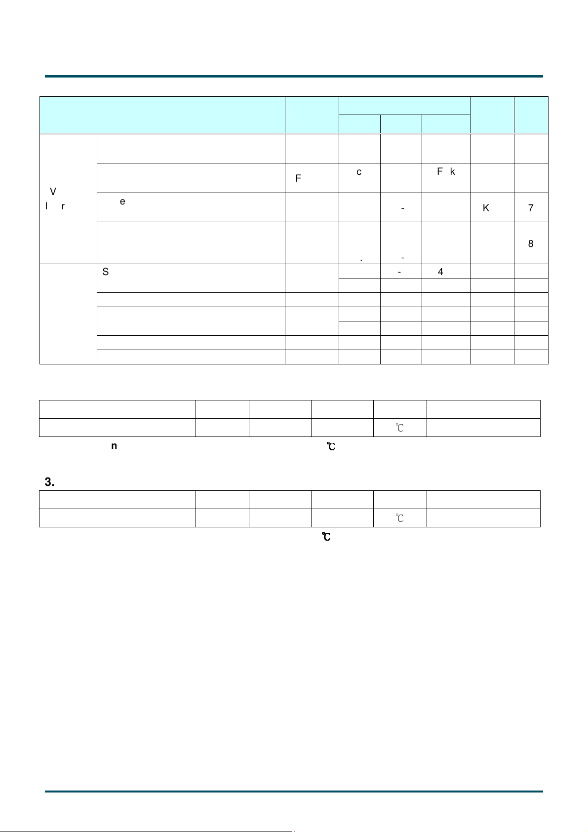
3.1.2: AC Characteristics
LVDS
Interface
I2C
Interface
Parameter Symbol
Input Channel Pair Skew Margin t
Receiver Clock : Spread Spectrum
Modulation range
Receiver Clock : Spread Spectrum
Modulation frequency
Receiver Data Input Margin
Fclk = 85 MHz
Fclk = 65 MHz
I2C clock high level
I2C clock low level T
I2C data hold time
SDA and SCL rise time TR -- -- 1000 ns
SDA and SCL fall time TF -- -- 300 ns
SKEW (CP)
Fclk_ss
Fss
tRMG
F
SCL
T
SCHi
SCLo
T
SDS
T
SDH
Min. Typ. Max
-500 -- +500 ps 6
Fclk
-3%
30
-0.4
-0.5
1.2 -- -- us
0 -- 400 KHZ SCL clock frequency
0.6 --
100 -- -- ns I2C data setup time
0 -- 900 ns
Value
--
--
--
--
Fclk
+3%
200
0.4
0.5
-- us
Unit Note
MHz
KHz
ns
7
7
8
3.1.3: Driver Characteristics
Item Symbol Min Max Unit condition
Driver Surface Temperature DST 100
Note : Any point on the driver surface must be less than 100
3.1.4: TCON Characteristics
Item Symbol Min Max Unit condition
TCON Surface Temperature TST 85
Note : Any point on the TCON surface must be less than 85
[℃]
℃℃℃℃
under any conditions.
[℃]
℃℃℃℃
under any conditions.
Note
Note
Page 8

Note :
s
µ
1. Test Condition:
(1) V
= 12.0V
DD
(2) Fv = 60Hz
(3) Fclk= 82MHz
(4) Temperature = 25 ℃
(5) Typ. Input current : White Pattern
Max. Input current: Heavy loading pattern defined by AUO
2. Measurement condition : Rising time = 400us
90%
VVVV
DD
DD
DDDD
GND
GND
GNDGND
10%
3. Test Condition:
(1) The measure point of V
is in LCM side after connecting the System Board and LCM.
RP
(2) Under Max. Input current spec. condition.
4. V
= 1.25V
ICM
L V D S -
V
IC M
L V D S +
G N D
0 V
400
400
400400
|VID|
V
T H
|VID|
V
T L
|VID|
5. The measure points of V
and V
IH
are in LCM side after connecting the System Board and LCM.
IL
Page 9

6. Input Channel Pair Skew Margin.
Note: x = 0, 1, 2, 3, 4
7. LVDS Receiver Clock SSCG (Spread spectrum clock generator) is defined as below figures.
1111////FFFF
SS
SS
SSSS
Fclk
Fclk____ss
FclkFclk
ss((((max
max))))
ssss
maxmax
Fclk
Fclk
FclkFclk
Fclk
Fclk____ss
FclkFclk
ss((((min
min))))
ssss
minmin
Page 10
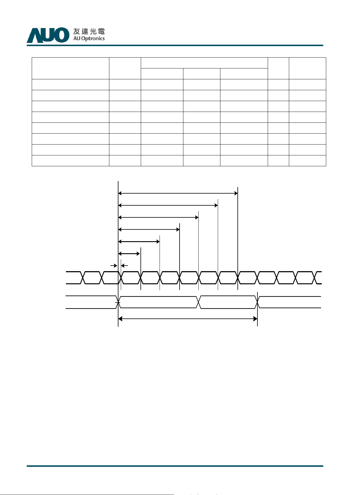
8. Receiver Data Input Margin
T650HVN03.2 SKD Product Specification
Rev. 01
Parameter Symbol
Min Type Max
Input Clock Frequency Fclk Fclk (min) -- Fclk (max) MHz
Input Data Position0 tRIP1 -|tRMG| 0 |tRMG| ns
Input Data Position1 tRIP0 T/7-|tRMG| T/7 T/7+|tRMG| ns
Input Data Position2 tRIP6 2T/7-|tRMG|
Input Data Position3 tRIP5 3T/7-|tRMG|
Input Data Position4 tRIP4 4T/7-|tRMG|
Input Data Position5 tRIP3 5T/7-|tRMG|
Input Data Position6 tRIP2 6T/7-|tRMG|
Rating
Unit
2T/7 2T/7+|tRMG| ns
3T/7 3T/7+|tRMG| ns
4T/7 4T/7+|tRMG| ns
5T/7 5T/7+|tRMG| ns
6T/7 6T/7+|tRMG| ns
tRIP2
tRIP3
tRIP4
tRIP5
Note
T=1/Fclk
LVDS-Rx
Input Data
LVDS-Rx
Input Clock
tRIP6
tRIP0
tRIP1
Rx1 Rx0 Rx6 Rx5 Rx4 Rx3 Rx2 Rx1 Rx0 Rx6Rx2Rx3
VVVV
=
= 0000VVVV
= =
diff
diff
diff diff
1/Fclk=T
© Copyright AUO Optronics Corp. 2013 All Rights Reserved. Page 10 /
28
10
Page 11
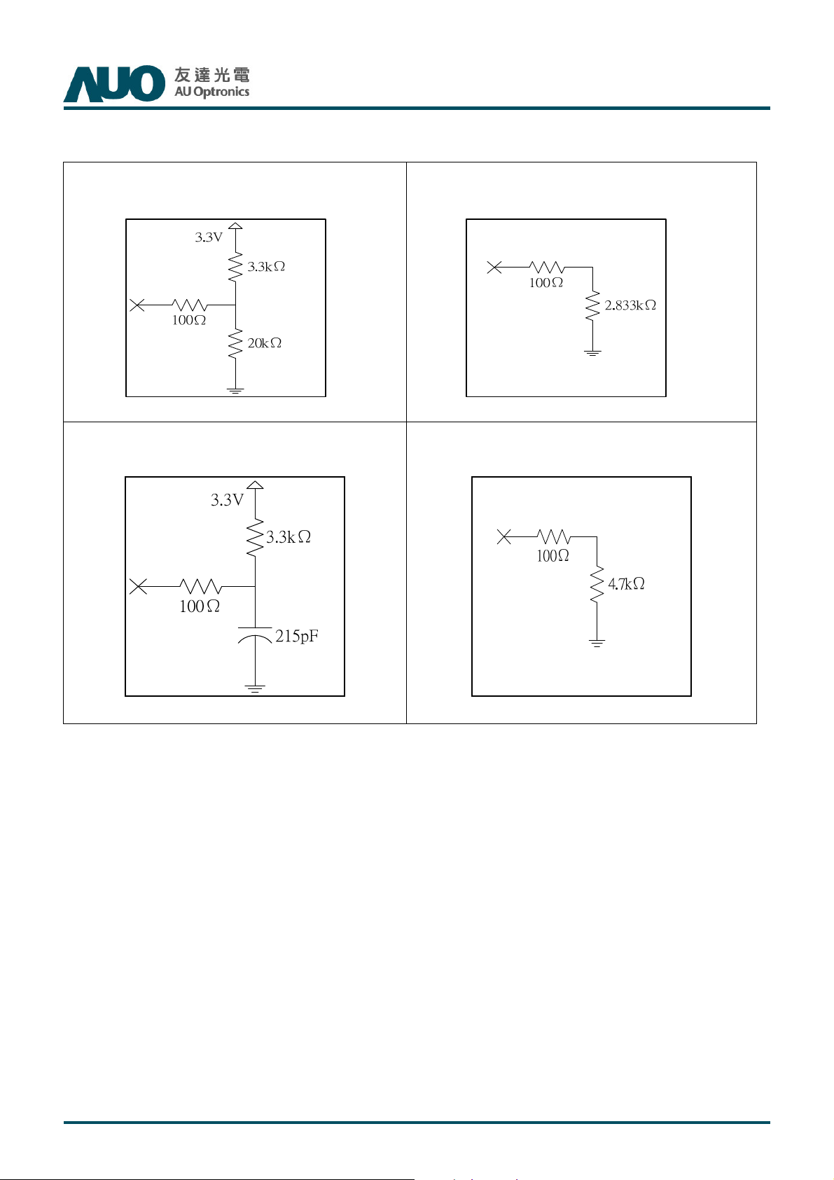
T650HVN03.2 SKD Product Specification
3.2 Interface Connections
3.2.1: LVDS connector control and I2C pin description
Rev. 01
Note * : Open/High(3.3V)
Note **** : SCL/SDA
Note ** : Open/Low(GND)
Note ***** : WP
© Copyright AUO Optronics Corp. 2013 All Rights Reserved. Page 11 / 28
Page 12
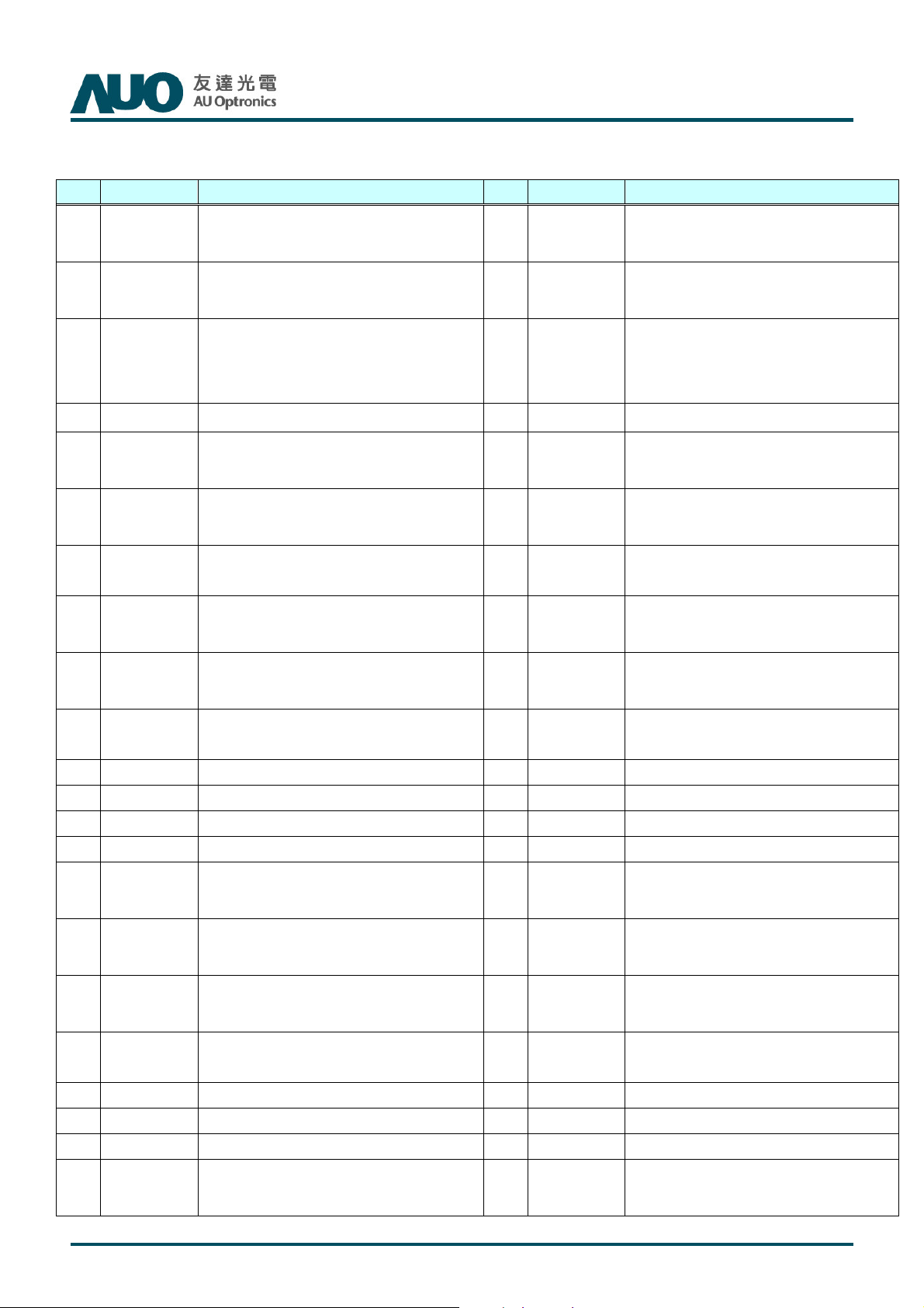
No connection (for AUO test only. Do not
No connection (for AUO test only. Do not
. Do not
No connection (for AUO test only. Do not
tion (for AUO test only. Do not
No connection (for AUO test only. Do not
3.2.2:
LCD connector: FI-RE51S-HF (JAE, LVDS connector)
T650HVN03.2 SKD Product Specification
Rev. 01
PIN
1
2
3
4
5
6
7 LVDS_SEL
8
Symbol Description PIN
N.C.
SCL EEPROM Serial Clock
WP
SDA EEPROM Serial Data
N.C.
N.C.
N.C.
connect)
EEPROM Write Protection
High(3.3V) for Writable,
Low(GND) for Protection
connect)
No connection (for AUO test only
connect)
Open/High(3.3V) for NS,
Low(GND) for JEIDA
connect)
26
27
28
29
30
31
32
33
Symbol Description
No connection (for AUO test only. Do
N.C.
not connect)
No connection (for AUO test only. Do
N.C.
not connect)
CH2_0- LVDS Channel 2, Signal 0-
CH2_0+ LVDS Channel 2, Signal 0+
CH2_1- LVDS Channel 2, Signal 1-
CH2_1+ LVDS Channel 2, Signal 1+
CH2_2- LVDS Channel 2, Signal 2-
CH2_2+ LVDS Channel 2, Signal 2+
9
10
11
12
13
14
15
16
17
18
19 CH1_CLK-
20 CH1_CLK+
21
22
N.C.
N.C.
GND Ground 36 CH2_CLK+
CH1_0- LVDS Channel 1, Signal 0- 37
CH1_0+ LVDS Channel 1, Signal 0+ 38
CH1_1- LVDS Channel 1, Signal 1- 39
CH1_1+ LVDS Channel 1, Signal 1+ 40
CH1_2- LVDS Channel 1, Signal 2- 41
CH1_2+ LVDS Channel 1, Signal 2+ 42
GND Ground 43
GND Ground 46
CH1_3- LVDS Channel 1, Signal 3- 47
No connec
LVDS Channel 1, Clock - 44
LVDS Channel 1, Clock + 45
connect)
connect)
34
35 CH2_CLK-
GND Ground
GND Ground
CH2_3- LVDS Channel 2, Signal 3-
CH2_3+ LVDS Channel 2, Signal 3+
CH2_4-
CH2_4+
N.C.
N.C.
GND Ground
GND Ground
GND Ground
N.C.
LVDS Channel 2, Clock -
LVDS Channel 2, Clock +
LVDS Channel 2,Signal 4-(for 10bit
input)
LVDS Channel 2,Signal 4+(for 10bit
input)
No connection (for AUO test only. Do
not connect)
No connection (for AUO test only. Do
not connect)
No connection (for AUO test only. Do
not connect)
© Copyright AUO Optronics Corp. 2013 All Rights Reserved. Page 12 / 28
Page 13
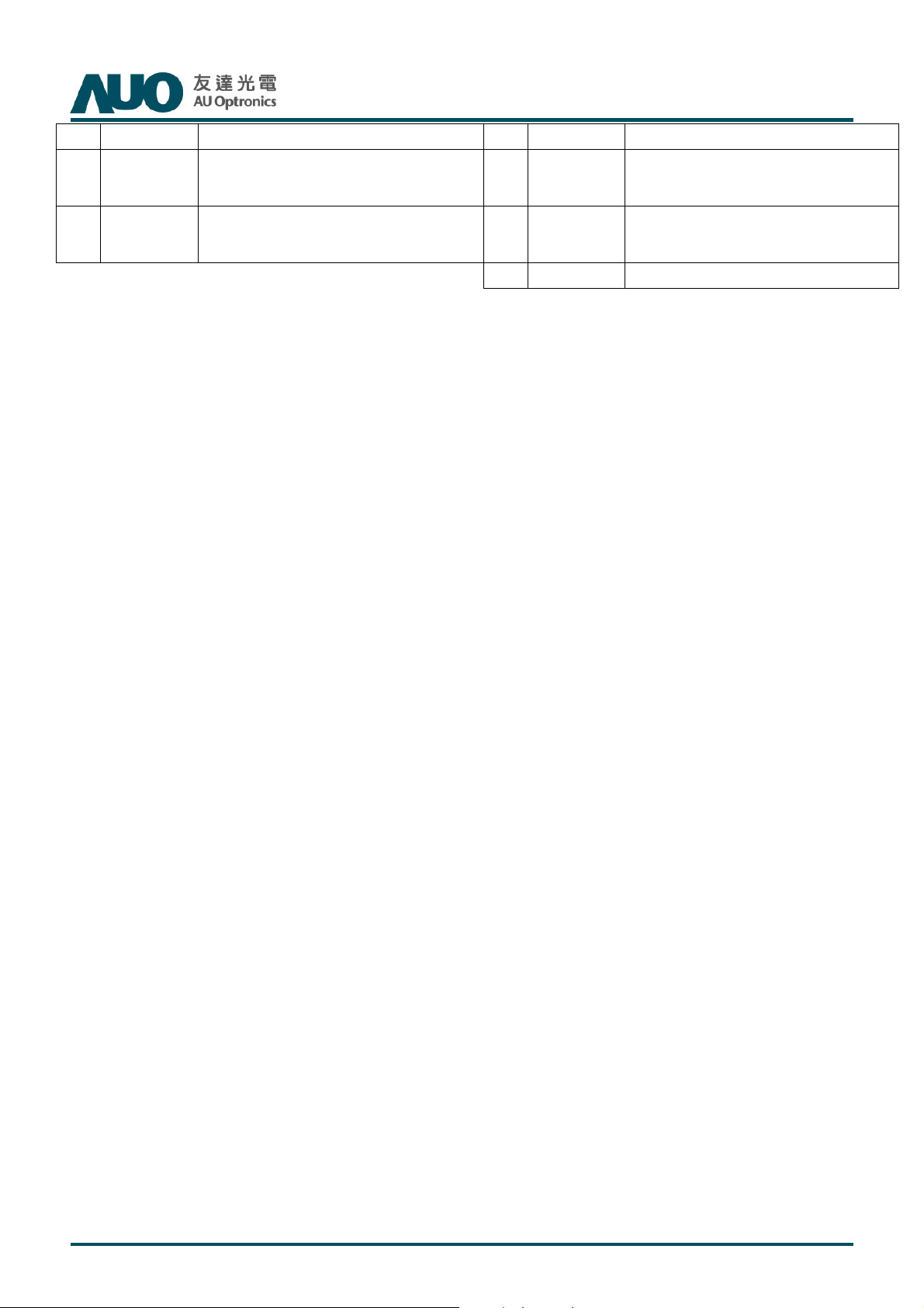
23
24
CH1_3+ LVDS Channel 1, Signal 3+ 48
CH1_4-
LVDS Channel 1,Signal 4-(for 10bit
input)
49
T650HVN03.2 SKD Product Specification
Rev. 01
V
DD
V
DD
Power Supply, +12V DC Regulated
Power Supply, +12V DC Regulated
LVDS Channel 1,Signal 4+(for 10bit
input)
51
50
V
DD
V
DD
Power Supply, +12V DC Regulated
Power Supply, +12V DC Regulated
25
CH1_4+
Note: N.C. : please leave this pin unoccupied. It can not be connected by any signal
(Low/GND/High). Note: Open / High(3.3V) / Low(GND)/ WP / SDA / SCL described in 3.2.1
© Copyright AUO Optronics Corp. 2013 All Rights Reserved. Page 13 / 28
Page 14
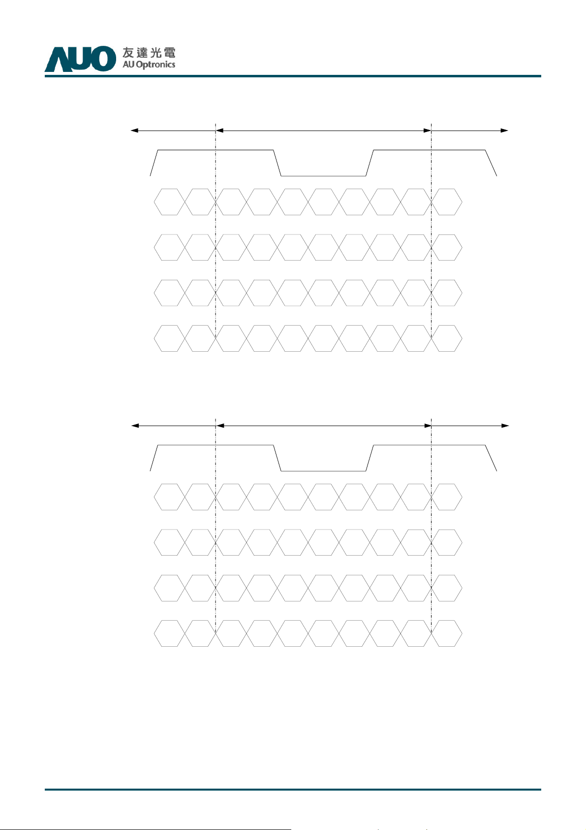
3.2.3: LVDS Option for 8bit
LVDS Option = High/OpenNS
P re v io u s C ycle C urrent C ycle N e x t C yc le
P re v io u s C ycle C urrent C ycle N e x t C yc le
P re v io u s C ycle C urrent C ycle N e x t C yc le P re v io u s C ycle C urrent C ycle N e x t C yc le
C loc k
C loc k
C loc kClo ck
C H x
C H x____ 0000 ++++
C H xC H x
C H x
C H x____ 0000 ----
C H xC H x
C H x
C H x____ 1111 ++++
C H xC H x
C H x
C H x____ 1111 ----
C H xC H x
C H x
C H x____ 2222 ++++
C H xC H x
C H x
C H x____ 2222 ----
C H xC H x
C H x
C H x____ 3333 ++++
C H xC H x
C H x
C H x____ 3333 ----
C H xC H x
Note: x = 1, 2, 3, 4…
T650HVN03.2 SKD Product Specification
D EBBBB 2222BBBB 3333 BBBB 4444BBBB 5555N A
D ED E
N ARRRR 6666RRRR 7777 GGGG 6666GGGG 7777BBBB 6666 RRRR 7777
N AN A
N A D E
N AN A
N A BBBB 3333
N AN A
RRRR 0000RRRR 5555 GGGG 0000GGGG 0000RRRR 0000RRRR 1111 RRRR 2222RRRR 3333RRRR 4444 RRRR 1111
GGGG 1111BBBB 0000 BBBB 1111BBBB 1111GGGG 1111GGGG 2222 GGGG 3333GGGG 4444GGGG 5555 GGGG 2222
BBBB 2222N A
RRRR 6666BBBB 7777 N A
D ED E
D ED E
N AN A
N AN A
Rev. 01
LVDS Option = LowJEIDA
P re v io u s C ycle C urre nt C ycle N ex t C ycle
P re v io u s C ycle C urre nt C ycle N ex t C ycle
P re v io u s C ycle C urre nt C ycle N ex t C ycle P re vio u s C yc le C u r re n t C y c l e N ext C ycle
C loc k
C loc k
C loc kClo ck
C H x
C H x ____ 0000 ++++
C H xCH x
C H x
C H x ____ 0000 ----
C H xCH x
C H x
C H x ____ 1111 ++++
C H xCH x
C H x
C H x ____ 1111 ----
C H xCH x
C H x
C H x ____ 2222 ++++
C H xCH x
C H x
C H x ____ 2222 ----
C H xCH x
C H x
C H x ____ 3333 ++++
C H xCH x
C H x
C H x ____ 3333 ----
C H xCH x
Note: x = 1, 2, 3, 4…
D EBBBB 4444BBBB 5555 BBBB 6666BBBB 7777N A
D ED E
N ARRRR 0000RRRR 1111 GGGG 0000GGGG 1111BBBB 0000 RRRR 1111
N AN A
N A D E
N AN A
N A BBBB 5555
N AN A
RRRR 2222RRRR 7777 GGGG 2222GGGG 2222RRRR 2222RRRR 3333 RRRR 4444RRRR 5555RRRR 6666 RRRR 3333
GGGG 3333BBBB 2222 BBBB 3333BBBB 3333GGGG 3333GGGG 4444 GGGG 5555GGGG 6666GGGG 7777 GGGG 4444
BBBB 4444N A
RRRR 0000BBBB 1111 N A
D ED E
D ED E
N AN A
N AN A
© Copyright AUO Optronics Corp. 2013 All Rights Reserved. Page 14 / 28
Page 15
T650HVN03.2 SKD Product Specification
Rev. 01
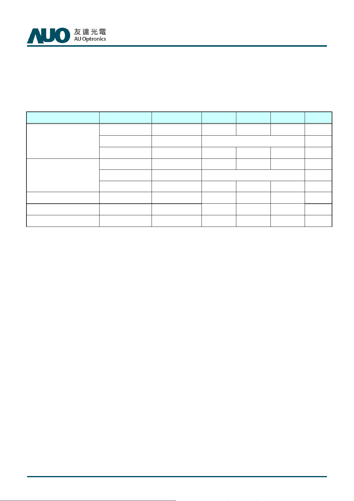
3.3 Signal Timing Specification
This is the signal timing required at the input of the user connector. All of the interface signal timing should be
satisfied with the following specifications for its proper operation.
Timing Table (DE only Mode)
Signal Item Symbol Min. Typ. Max Unit
Period Tv 1100 1125 1480 Th
Vertical Section
Active Tdisp (v) 1080
Blanking Tblk (v) 20 45 400 Th
Period Th 1040 1100 1328 Tclk
Horizontal Section
Active Tdisp (h) 960
Blanking Tblk (h) 80 140 368 Tclk
Clock Frequency Fclk=1/Tclk 50 74.25 82 MHz
Vertical Frequency Frequency Fv 47 60 63 Hz
Horizontal Frequency
Frequency Fh 60 67.5 73 KHz
Notes:
(1) Display position is specific by the rise of DE signal only.
Horizontal display position is specified by the rising edge of 1st DCLK after the rise of 1st DE, is displayed on the
left edge of the screen.
(2) Vertical display position is specified by the rise of DE after a “Low” level period equivalent to eight times of
horizontal period. The 1st data corresponding to one horizontal line after the rise of 1st DE is displayed at the top
line of screen.
(3) If a period of DE “High” is less than 1920 DCLK or less than 1080 lines, the rest of the screen displays black.
(4) The display position does not fit to the screen if a period of DE “High” and the effective data period do not
synchronize with each other.
© Copyright AUO Optronics Corp. 2013 All Rights Reserved. Page 15 / 28
Page 16
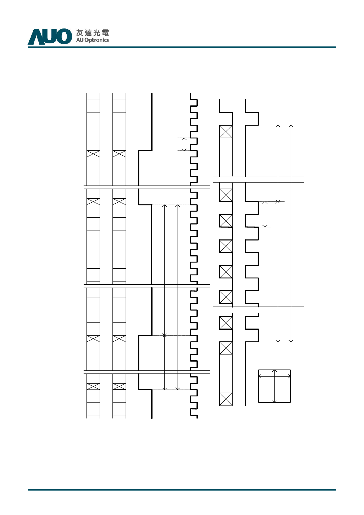
3.4 Signal Timing Waveforms
T650HVN03.2 SKD Product Specification
Rev. 01
CH2
Pixel
M-6
Pixel
M-4
Pixel
M-2
Pixel
M
Invalid Data
Pixel
2
Pixel
4
Pixel
6
Pixel
8
Pixel
10
Pixel
12
CH1
Pixel
M-7
Pixel
M-5
Pixel
M-3
Pixel
M-1
Invalid Data
Pixel
1
Pixel
3
Pixel
5
Pixel
7
Pixel
9
Pixel
11
DE
Tdisp(h) Tblk(h)
CLK
RGB
Data
Line
N
Tclk
Invalid Data Invalid Data
Line
1
Line
2
Th
Line
3
Line
4
DE
Th
Tv
Tdisp(v)Tblk(v)
Pixel
M-4
Pixel
M-2
Pixel
M
Invalid Data
Pixel
2
Pixel
4
Pixel
M-5
Pixel
M-3
Pixel
M-1
Invalid Data
Pixel
1
Pixel
3
Line
N
N L in e
N L in e
N L in eN L in e
M
M
M
M
p
p
p
p
i
i
i
i
x
x
x
x
e
e
e
e
l
l
l
l
© Copyright AUO Optronics Corp. 2013 All Rights Reserved. Page 16 / 28
Page 17
T650HVN03.2 SKD Product Specification
Rev. 01
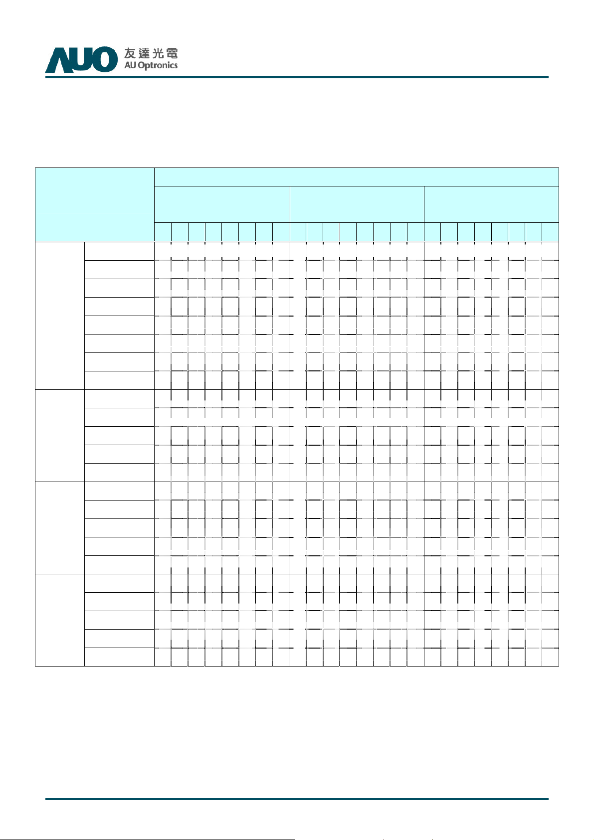
3.5 Color Input Data Reference
The brightness of each primary color (red, green and blue) is based on the 8 bit gray scale data input for the color;
the higher the binary input, the brighter the color. The table below provides a reference for color versus data input.
COLOR DATA REFERENCE
Input Color Data
Basic
Color
R
Color
MSB LSB
R7 R6 R5 R4 R3 R2 R1 R0 G7 G6 G5 G4 G3 G2 G1 G0 B7 B6 B5 B4 B3 B2 B1 B0
Black 0 0 0 0 0 0 0 0 0 0 0 0 0 0 0 0 0 0 0 0 0 0 0 0
Red(255) 1 1 1 1 1 1 1 1 0 0 0 0 0 0 0 0 0 0 0 0 0 0 0 0
Green(255) 0 0 0 0 0 0 0 0 1 1 1 1 1 1 1 1 0 0 0 0 0 0 0 0
Blue(255) 0 0 0 0 0 0 0 0 0 0 0 0 0 0 0 0 1 1 1 1 1 1 1 1
Cyan 0 0 0 0 0 0 0 0 1 1 1 1 1 1 1 1 1 1 1 1 1 1 1 1
Magenta 1 1 1 1 1 1 1 1 0 0 0 0 0 0 0 0 1 1 1 1 1 1 1 1
Yellow 1 1 1 1 1 1 1 1 1 1 1 1 1 1 1 1 0 0 0 0 0 0 0 0
White 1 1 1 1 1 1 1 1 1 1 1 1 1 1 1 1 1 1 1 1 1 1 1 1
RED(000) 0 0 0 0 0 0 0 0 0 0 0 0 0 0 0 0 0 0 0 0 0 0 0 0
RED(001) 0 0 0 0 0 0 0 1 0 0 0 0 0 0 0 0 0 0 0 0 0 0 0 0
----
RED(254) 1 1 1 1 1 1 1 0 0 0 0 0 0 0 0 0 0 0 0 0 0 0 0 0
RED(255) 1 1 1 1 1 1 1 1 0 0 0 0 0 0 0 0 0 0 0 0 0 0 0 0
RED
MSB LSB
GREEN
BLUE
MSB LSB
GREEN(000) 0 0 0 0 0 0 0 0 0 0 0 0 0 0 0 0 0 0 0 0 0 0 0 0
GREEN(001) 0 0 0 0 0 0 0 0 0 0 0 0 0 0 0 1 0 0 0 0 0 0 0 0
G
----
GREEN(254) 0 0 0 0 0 0 0 0 1 1 1 1 1 1 1 0 0 0 0 0 0 0 0 0
GREEN(255) 0 0 0 0 0 0 0 0 1 1 1 1 1 1 1 1 0 0 0 0 0 0 0 0
BLUE(000) 0 0 0 0 0 0 0 0 0 0 0 0 0 0 0 0 0 0 0 0 0 0 0 0
BLUE(001) 0 0 0 0 0 0 0 0 0 0 0 0 0 0 0 0 0 0 0 0 0 0 0 1
B
----
BLUE(254) 0 0 0 0 0 0 0 0 0 0 0 0 0 0 0 0 1 1 1 1 1 1 1 0
BLUE(255) 0 0 0 0 0 0 0 0 0 0 0 0 0 0 0 0 1 1 1 1 1 1 1 1
© Copyright AUO Optronics Corp. 2013 All Rights Reserved. Page 17 / 28
Page 18
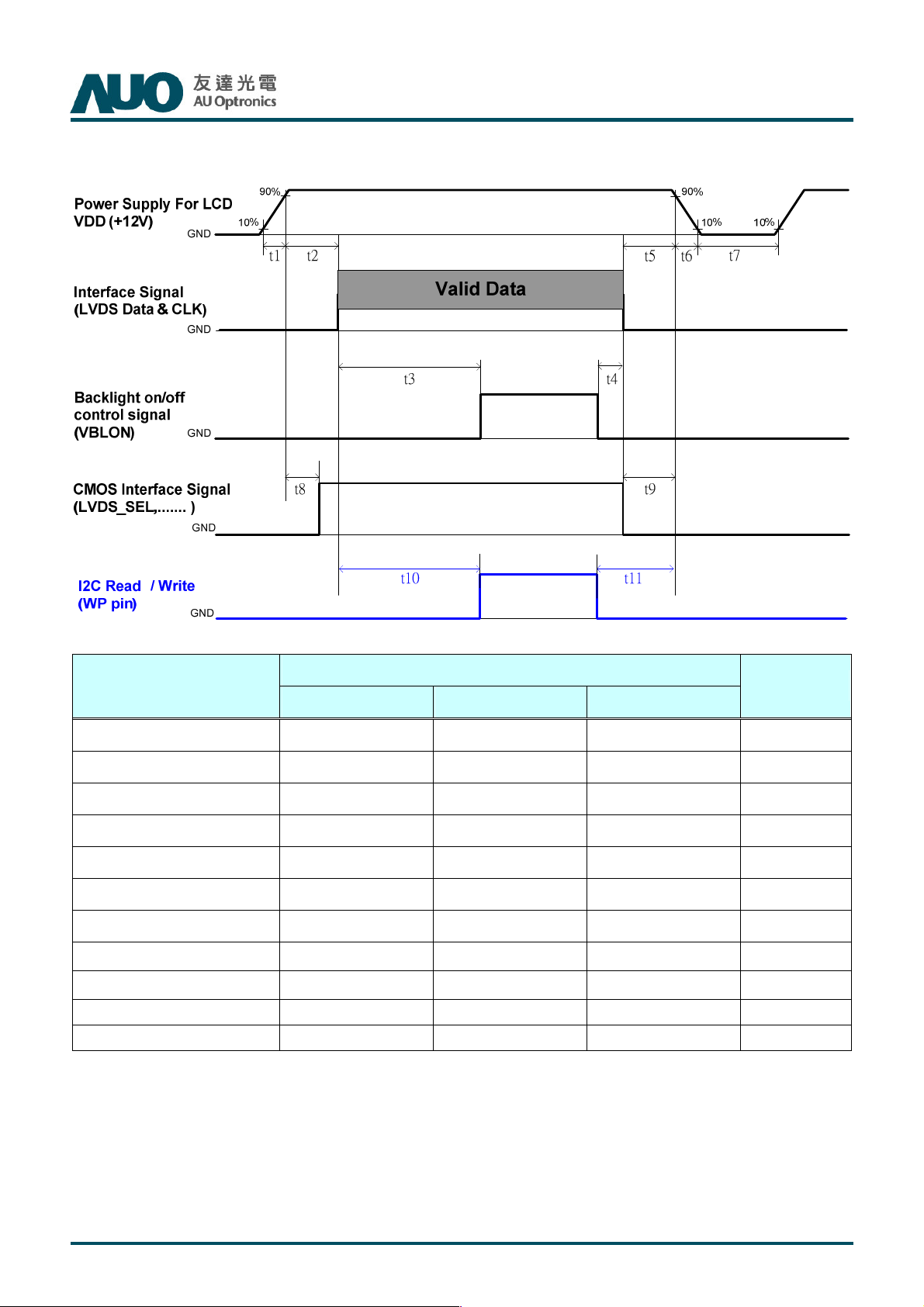
3.6 Power Sequence for LCD
T650HVN03.2 SKD Product Specification
Rev. 01
Values
Parameter
Unit
Min. Type. Max.
t1 0.4 --- 30 ms
t2 0.1 --- 50 ms
t3 450 --- --- ms
t4 0*1 --- --- ms
t5 0 --- --- ms
t6 --- --- ---*2 ms
t7 500 --- --- ms
t8
10*3
--- 50 ms
t9 0 --- --- ms
t10 450 --- --- ms
t11 150 --- --- ms
Note:
(1) t4=0 : concern for residual pattern before BLU turn off.
(2) t6 : voltage of VDD must decay smoothly after power-off. (customer system decide this value)
(3) When CMOS Interface signal is N.C. (no connection), opened in Transmitted end, t8 timing spec can be
negligible.
© Copyright AUO Optronics Corp. 2013 All Rights Reserved. Page 18 / 28
Page 19
T650HVN03.2 SKD Product Specification
Rev. 01
4. Optical Specification
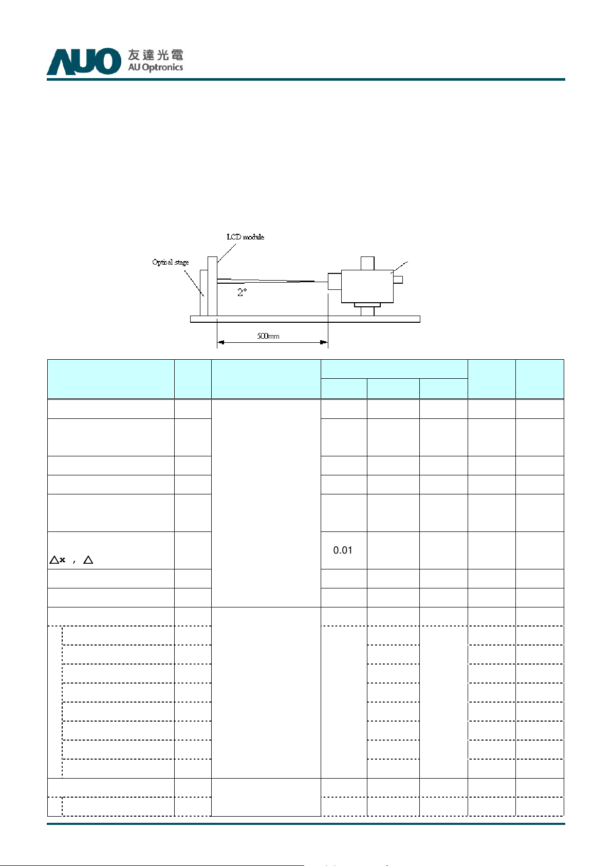
Optical characteristics are determined after the unit has been ‘ON’ and stable for approximately 45 minutes in a
dark environment at 25°C. The values specified are at an approximate distance 50cm from the LCD surface at a
viewing angle of φ and θ equal to 0°.
Fig.1 presents additional information concerning the measurement equipment and method.
SR3 or equivalent
Parameter Symbol
Contrast Ratio CR 4000 5000 -- 1
Surface Luminance
(White)
256 Gray Gamma(Center)
L/R Gamma -0.25 Center +0.25 3
Low Gray Uniformity
(Center 5nits)
Color Uniformity (9 point)
△△△△
x ,
△△△△
y
Response Time (G to G) Tγ -- 8 -- Ms 4
Center Transmittance T%
Color Chromaticity 5
Red RX 0.650
LWH
1.9 2.2 2.5 3
-- -- 55% 3
-0.011
Condition
Min. Typ. Max
--
*
4.35 % 7
Values
300 -- cd/m2 2
0 0.011 3
Unit Notes
RY 0.329
Green GX 0.313
GY 0.638
Blue BX 0.153
BY 0.036
White WX 0.276
W
Viewing Angle 6
x axis, right(φ=0°) θr
Y
With AUO Module
*
Typ.-0.03
-- 89 -- degree
0.292
Typ.+0.03
© Copyright AUO Optronics Corp. 2013 All Rights Reserved. Page 19 / 28
Page 20
2 3
7
T650HVN03.2 SKD Product Specification
x axis, left(φ=180°) θl -- 89 -- degree
Rev. 01
y axis, up(φ=90°) θu -- 89 -- degree
y axis, down (φ=270°) θd -- 89 -- degree
1. Light source here is the BLU of AUO T645HW05 V0 module.
*
The typical values of contrast ratio, surface luminance, luminance variation, and color chromaticity are
based on the average value of DVT samples with T645HW05 V0 backlight.
*
T650HW05 V0 LED lightbar and LED backlight structure are designed by customers, AUO can not
guarantee the typical value of NTSC, RGBW, contrast ratio, luminance, and maximum value of luminance
variation.
2. Contrast Ratio (CR) is defined mathematically as:
Surface Luminance of
Contrast Ratio=
Surface Luminance of
3. The criteria is for reference. When condition about out of criteria happened, to clarify root cause due to open
cell or back light unit is necessary.
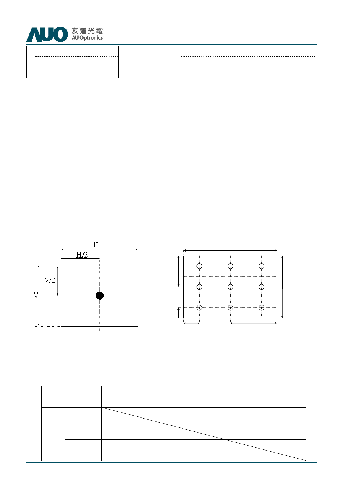
FIG. 2 Luminance
L
on5
L
off5
V
H/2
H/6
1
H
V/2 V/6
4. The variation in surface luminance, δWHITE is defined (center of Screen) as:
δ
WHITE(9P)
= Maximum(L
on1
, L
on2
,…,L
)/ Minimum(L
on9
on1
, L
on2
,…L
on9
)
5. Response time Tγ is the average time required for display transition by switching the input signal for five
luminance ratio (0%,25%,50%,75%,100% brightness matrix) and is based on Fv=240Hz to optimize.
Target Measured
Response Time
0% 25% 50% 75% 100%
Start
0%
25%
50%
75%
100%
0% to 25% 0% to 50% 0% to 75% 0% to 100%
25% to 0% 25% to 50% 25% to 75% 25% to 100%
50% to 0% 50% to 25%
75% to 0% 75% to 25% 75% to 50%
100% to 0% 100% to 25% 100% to 50% 100% to 75%
50% to 75% 50% to 100%
75% to 100%
© Copyright AUO Optronics Corp. 2013 All Rights Reserved. Page 20 / 28
Page 21
T650HVN03.2 SKD Product Specification
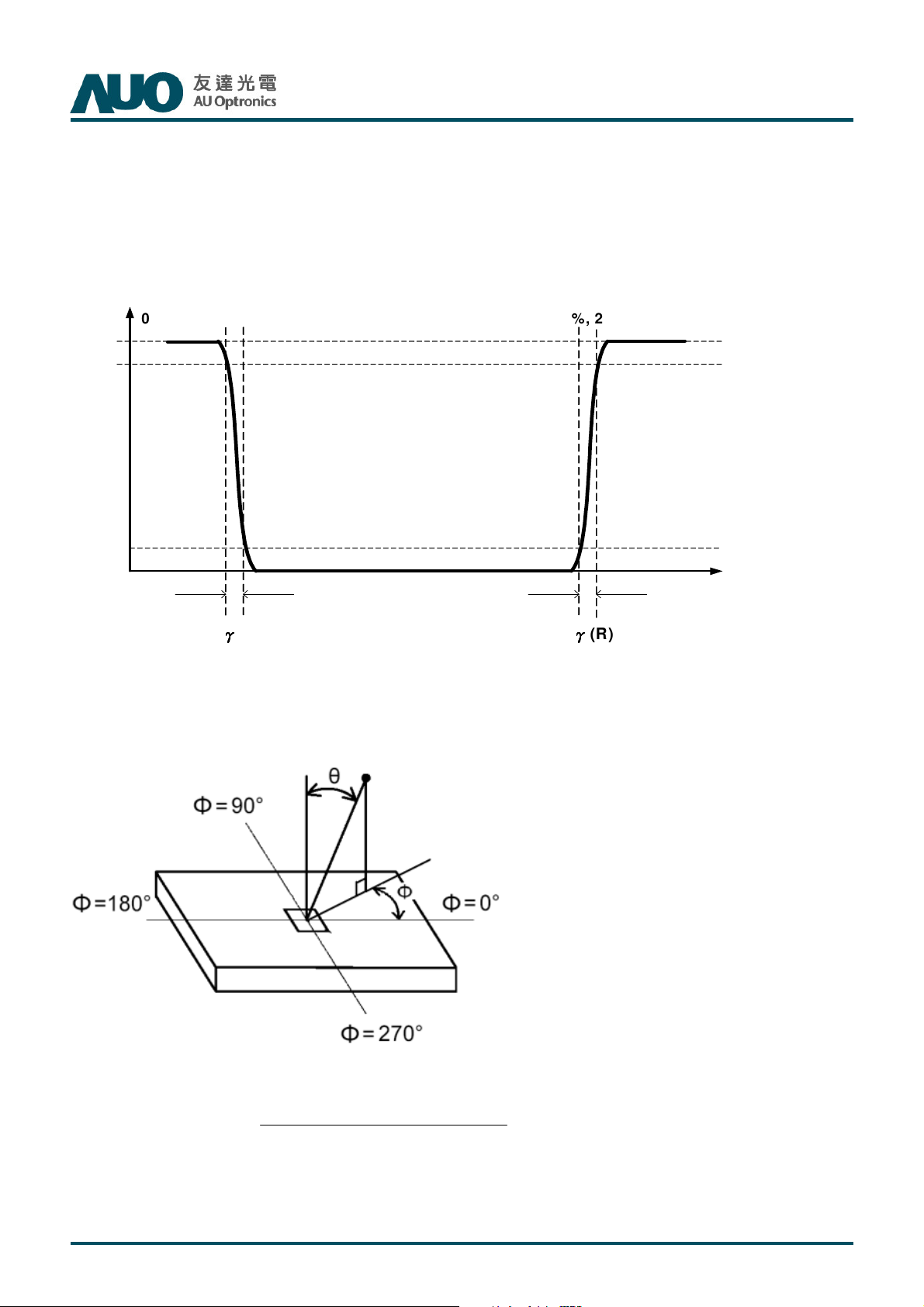
The response time is defined as the following figure and shall be measured by switching the input signal for
“any level of grey(bright) “ and “any level of gray(dark)”.
FIG.3 Response Time
Any level of gray (Bright) Any level of gray (Dark) Any level of gray (Bright)
Rev. 01
0% , 25%, 50% , 75% , 100%
0% , 25%, 50% , 75% , 100%
Photodetector
Output
0% , 25%, 50% , 75% , 100%
Time
T
(F)
γγγγ
6. Viewing angle is the angle at which the contrast ratio is greater than 10. The angles are determined for the
horizontal or x axis and the vertical or y axis with respect to the z axis which is normal to the LCD surface. For
more information see FIG4.
FIG.4 Viewing Angle
T
γγγγ
(R)
7. Definition of Transmittance (T%):
module LCD of Luminance
nceTransmitta ∗=
%001
backlight of Luminance
During transmittance measurement, the backlight of LCD module contains no brightness enhancement film.
Two diffuser sheets which diffuse the light source uniformly are suggested to use for transmittance
measurement.
© Copyright AUO Optronics Corp. 2013 All Rights Reserved. Page 21 / 28
Page 22
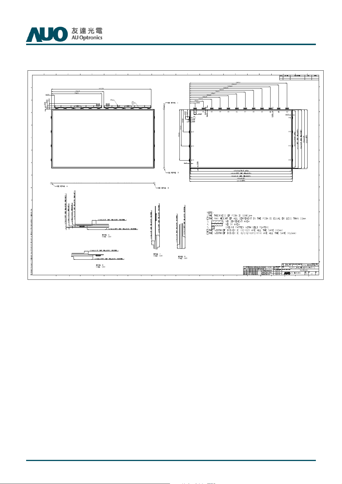
5. Open Cell Drawing
T650HVN03.2 SKD Product Specification
Rev. 01
© Copyright AUO Optronics Corp. 2013 All Rights Reserved. Page 22 / 28
Page 23
T650HVN03.2 SKD Product Specification
Rev. 01
6. Reliability Test Items (Reference Only)
Open cell reliability is based on T645HW04 V0 module RA result, except open cell packing vibration and
drop.
1 High temperature storage test 3 60℃, 300hrs
2 Low temperature storage test 3 -20℃, 300hrs
3 High temperature operation test 3 50℃, 300hrs
4 Low temperature operation test 3 -5℃, 300hrs
5 Vibration test (With carton) 1(PKG)
6 Drop test (With carton) 1(PKG)
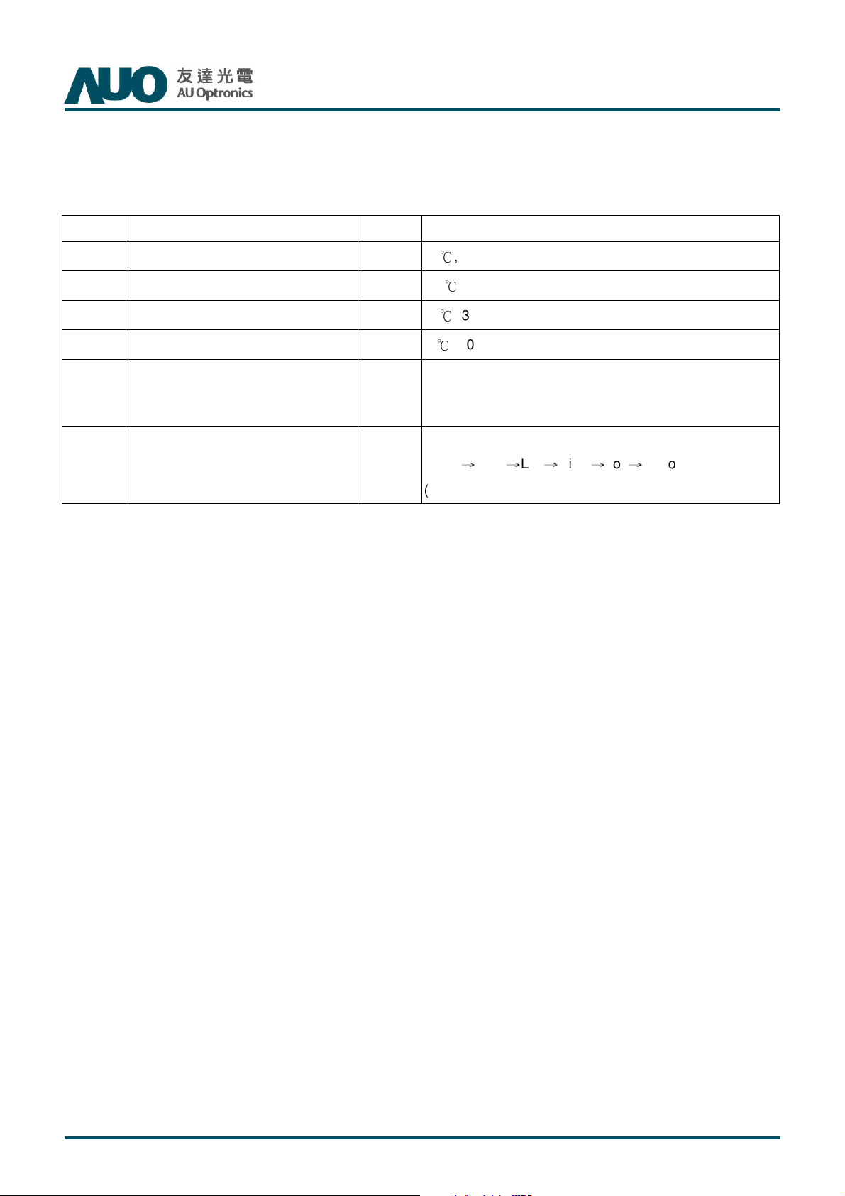
Note: Test item 1~4Test item 1~4 RA tests are done on AUO T645HW04 V0 panels.
Test Item Q’ty Condition
Random wave (1.5G RMS, 10-200Hz)
30mins/ Per each X,Y,Z axes
Drop Height: 10.2 cm, 6 Flats
(Front→Rear→Left→Right→Top→Bottom)
(ASTMD4169-I)
© Copyright AUO Optronics Corp. 2013 All Rights Reserved. Page 23 / 28
Page 24
7. Packing
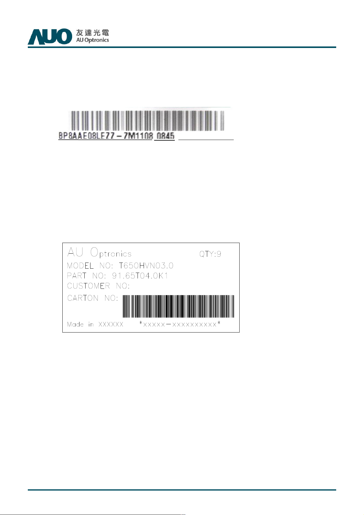
7-1 DEFINITION OF LABEL:
A. Open cell shipping Label:
(1)
AUO internal code
(2)
Manufactured date
(3)
Model name
(1) (2) (3)
T650HVN03.2 SKD Product Specification
TTTT65
650000HVN03.0
HVN03.0
6565
HVN03.0HVN03.0
Rev. 01
B. Carton Label:
© Copyright AUO Optronics Corp. 2013 All Rights Reserved. Page 24 / 28
Page 25
7-2 PACKING METHODS:
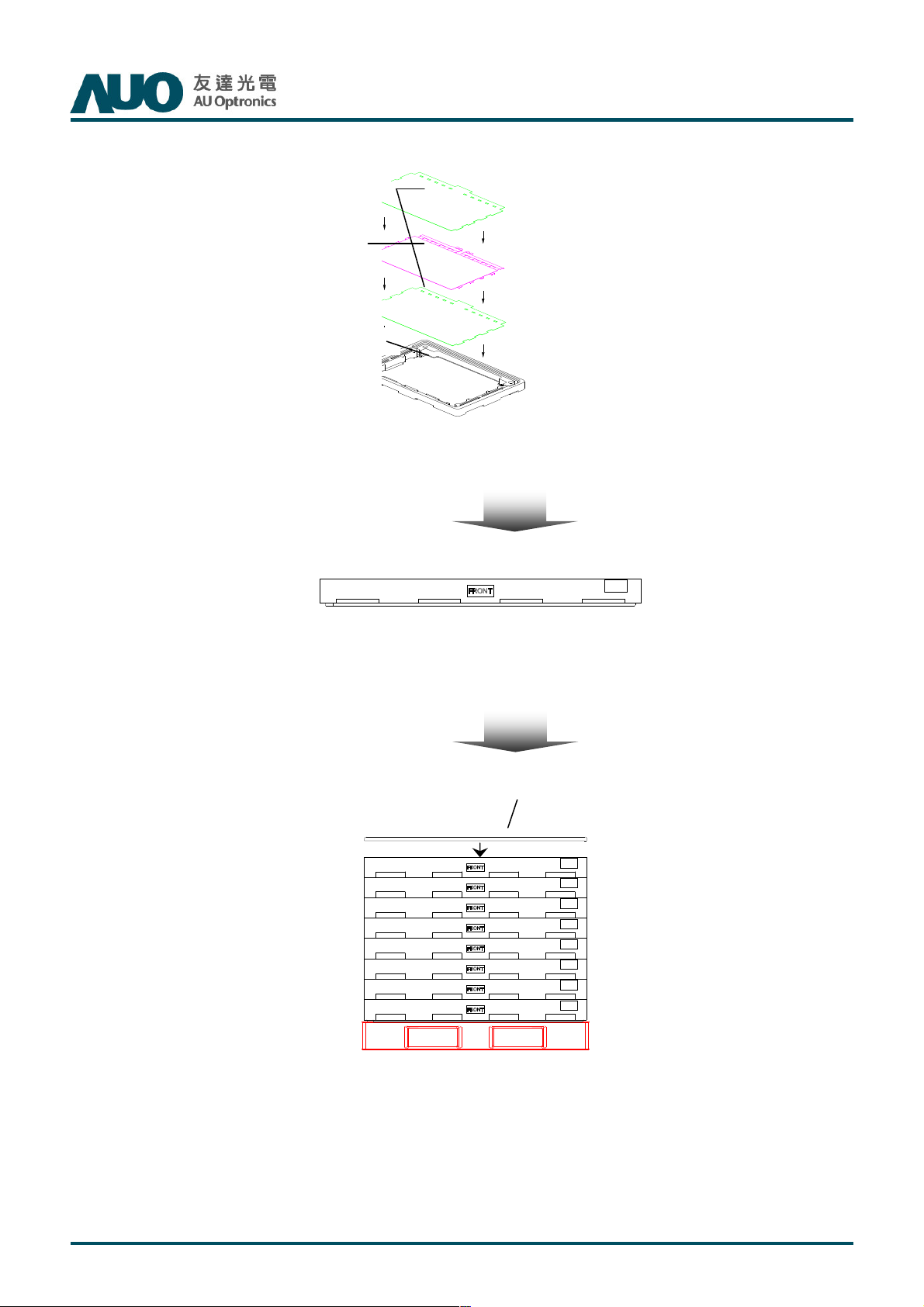
T650HVN03.2 SKD Product Specification
Rev. 01
EPE Spacer
Open Cell
Hybrid Box
1Box for 9 pcs cells & 10 pcs spacers
9 Pcs/Box,
EPP Top Cover
Pallet Dimension:1680*1150*140 mm
8 Boxes/Pallet, after stack 8 boxes, then put EPP top cover on it.
© Copyright AUO Optronics Corp. 2013 All Rights Reserved. Page 25 / 28
Page 26
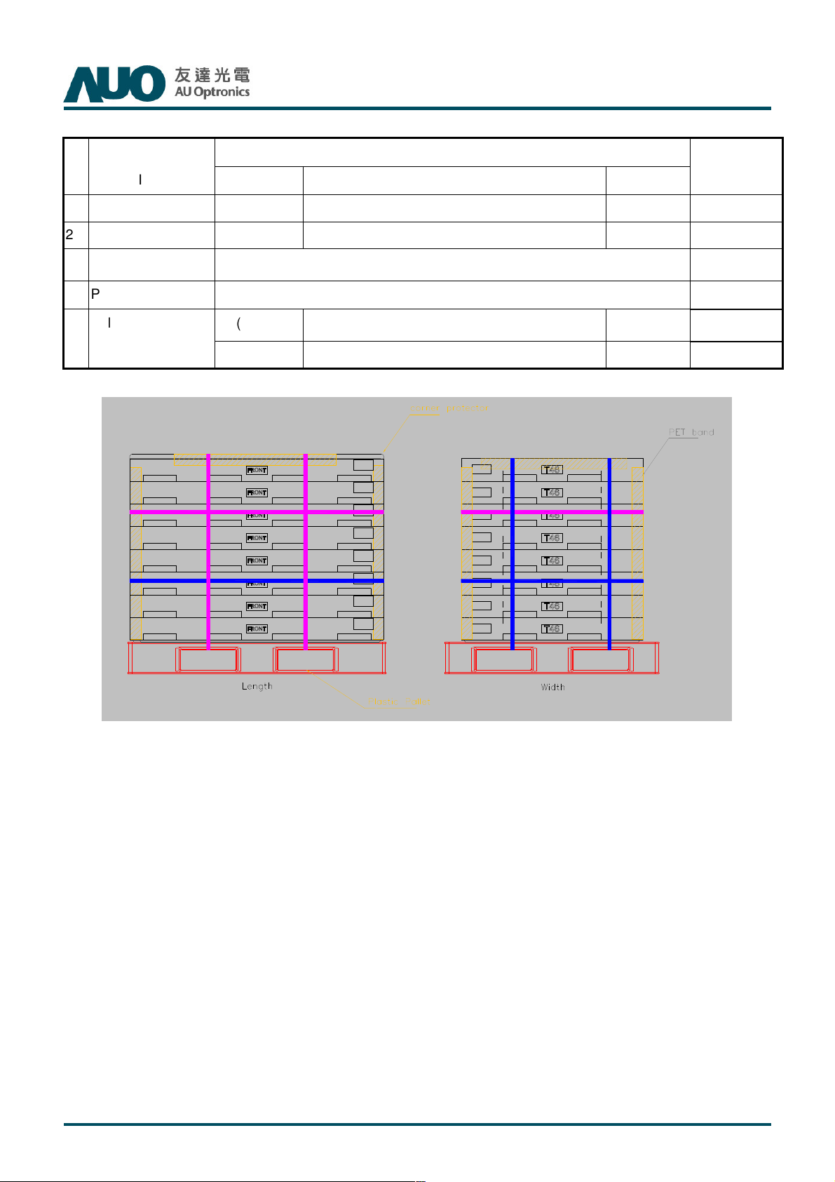
7-3 Pallet and Shipment Information
T650HVN03.2 SKD Product Specification
Rev. 01
Specification
Item
1 Packing Box 9 pcs/box 1650(L)mm*1070(W)mm*123(H)mm 52
2 Pallet 1 1680(L)mm*1150(W)mm*145(H)mm 20
3 Boxes per Pallet 9 boxes/Pallet (By Air) ; 9 Boxes/Pallet*Double Pallet (By Sea)
4 Panels per Pallet 81 pcs/pallet(By Air) ; 81 pcs/Pallet*Double Pallet (By Sea)
after packing
Qty. Dimension Weight (kg)
81 (by Air) 1680(L)mm*1070(W)mm*1079(H)mm (by Air) 438 (by Air)
162(by Sea) 1200(L)mm*1000(W)mm*2158(H)mm (by Sea) 876 (by Sea) 40ft HQ
Packing
Remark
5 Pallet
© Copyright AUO Optronics Corp. 2013 All Rights Reserved. Page 26 / 28
Page 27

T650HVN03.2 SKD Product Specification
8. PRECAUTIONS
Please pay attention to the followings when you use this TFT LCD module.
8-1 MOUNTING PRECAUTIONS
(1) You must mount a module using holes arranged in four corners or four sides.
(2) You should consider the mounting structure so that uneven force (ex. twisted stress) is not applied
to module. And the case on which a module is mounted should have sufficient strength so that
external force is not transmitted directly to the module.
(3) Please attach the surface transparent protective plate to the surface in order to protect the polarizer.
Transparent protective plate should have sufficient strength in order to the resist external force.
(4) You should adopt radiation structure to satisfy the temperature specification.
(5) Acetic acid type and chlorine type materials for the cover case are not desirable because the former
Rev. 01
generates corrosive gas of attacking the polarizer at high temperature and the latter cause circuit
broken by electro-chemical reaction.
(6) Do not touch, push or rub the exposed polarizer with glass, tweezers or anything harder than HB
pencil lead. And please do not rub with dust clothes with chemical treatment. Do not touch the
surface of polarizer for bare hand or greasy cloth. (Some cosmetics are detrimental to the polarizer.)
(7) When the surface becomes dusty, please wipe gently with absorbent cotton or other soft materials
like chamois soaks with petroleum benzene. Normal-hexane is recommended for cleaning the
adhesives used to attach front/ rear polarizer. Do not use acetone, toluene and alcohol because
they cause chemical damage to the polarizer.
(8) Wipe off saliva or water drops as soon as possible. Their long time contact with polarizer causes
deformations and color fading.
(9) Do not open the case because inside circuits do not have sufficient strength.
8-2 OPERATING PRECAUTIONS
(1) The device listed in the product specification sheets was designed and manufactured for TV
application
(2) The spike noise causes the mis-operation of circuits. It should be lower than following voltage:
V=±200mV(Over and under shoot voltage)
(3) Response time depends on the temperature. (In lower temperature, it becomes longer..)
(4) Brightness of CCFL depends on the temperature. (In lower temperature, it becomes lower.) And in
lower temperature, response time (required time that brightness is stable after turned on) becomes
longer.
(5) Be careful for condensation at sudden temperature change. Condensation makes damage to
polarizer or electrical contacted parts. And after fading condensation, smear or spot will occur.
(6) When fixed patterns are displayed for a long time, remnant image is likely to occur.
(7) Module has high frequency circuits. Sufficient suppression to the electromagnetic interference shall
© Copyright AUO Optronics Corp. 2013 All Rights Reserved. Page 27 / 28
Page 28
be done by system manufacturers. Grounding and shielding methods may be important to minimize
the interface.
8-3 ELECTROSTATIC DISCHARGE CONTROL
Since a module is composed of electronic circuits, it is not strong to electrostatic discharge. Make certain
that treatment persons are connected to ground through wristband etc. And don’t touch interface pin
directly.
8-4 PRECAUTIONS FOR STRONG LIGHT EXPOSURE
Strong light exposure causes degradation of polarizer and color filter.
8-5 STORAGE
When storing modules as spares for a long time, the following precautions are necessary.
(1) Store them in a dark place. Do not expose the module to sunlight or fluorescent light. Keep the
T650HVN03.2 SKD Product Specification
Rev. 01
temperature between 5 and 35 at normal humidity.
(2) The polarizer surface should not come in contact with any other object. It is recommended that they
be stored in the container in which they were shipped.
℃ ℃
8-6 HANDLING PRECAUTIONS FOR PROTECTION FILM
(1) The protection film is attached to the bezel with a small masking tape. When the protection film is
peeled off, static electricity is generated between the film and polarizer. This should be peeled off
slowly and carefully by people who are electrically grounded and with well ion-blown equipment or
in such a condition, etc.
(2) When the module with protection film attached is stored for a long time, sometimes there remains a
very small amount of glue still on the bezel after the protection film is peeled off.
(3) You can remove the glue easily. When the glue remains on the bezel or its vestige is recognized,
please wipe them off with absorbent cotton waste or other soft material like chamois soaked with
normal-hexane.
© Copyright AUO Optronics Corp. 2013 All Rights Reserved. Page 28 / 28
 Loading...