

Page 1
Global LCD Panel Exchange Center
www.panelook.com
Product Specification
AU OPTRONICS CORPORATION
M201SP01 V1
( V ) Preliminary Specification
( ) Final Specification
Module
Model Name
20.1” WSXGA+ Color TFT-LCD
M201SP01 V1
Customer Date
Approved by
Note: This Specification is subject to change without
notice.
Checked &
Approved by
Vincent CH Chen
Prepared by
Jack CC Hsu
Desktop Display Business Unit /
AU Optronics corporation
Date
Aug. 7 , 2007
Aug. 7 , 2007
document version 0.1 1/34
One step solution for LCD / PDP / OLED panel application: Datasheet, inventory and accessory!
www.panelook.com
Page 2

Global LCD Panel Exchange Center
www.panelook.com
Product Specification
AU OPTRONICS CORPORATION
M201SP01 V1
Contents
1. Handling Precautions.............................................................................................................. 4
2. General Description ................................................................................................................ 5
2.1 Display Characteristics .......................................................................................................................5
3. Functional Block Diagram .................................................................................................... 10
4. Absolute Maximum Ratings.................................................................................................. 11
4.1 Absolute Ratings of TFT LCD Module ............................................................................................ 11
4.2 Absolute Ratings of Backlight Unit.................................................................................................. 11
4.3 Absolute Ratings of Environment..................................................................................................... 11
5. Electrical characteristics ...................................................................................................... 13
5.1 TFT LCD Module .............................................................................................................................13
5.2 Backlight Unit................................................................................................................................... 14
6. Signal Characteristic............................................................................................................. 15
6.1 Pixel Format Image........................................................................................................................... 15
6.2 Signal Description............................................................................................................................. 16
6.3 The input data format........................................................................................................................ 19
6.4 Signal Electrical Characteristics ....................................................................................................... 21
6.5 Interface Timings .............................................................................................................................. 24
6.6 Power ON/OFF Sequence................................................................................................................. 26
7. Connector & Pin Assignment ............................................................................................... 27
7.1 TFT LCD Module .............................................................................................................................27
7.2 Backlight Unit................................................................................................................................... 30
8. Reliability Test ....................................................................................................................... 31
9. Shipping Label....................................................................................................................... 32
10. Mechanical Characteristics ................................................................................................ 33
document version 0.1 2/34
One step solution for LCD / PDP / OLED panel application: Datasheet, inventory and accessory!
www.panelook.com
Page 3
Global LCD Panel Exchange Center
www.panelook.com
Product Specification
AU OPTRONICS CORPORATION
M201SP01 V1
Record of Revision
Version & Date Page Old Description New Description Remark
0.1 2007/8/6
All First Edition for Customer
document version 0.1 3/34
One step solution for LCD / PDP / OLED panel application: Datasheet, inventory and accessory!
www.panelook.com
Page 4

Global LCD Panel Exchange Center
www.panelook.com
Product Specification
AU OPTRONICS CORPORATION
M201SP01 V1
1. Handling Precautions
1) Since front polarizer is easily damaged, pay attention not to scratch it.
2) Be sure to turn off power supply when inserting or disconnecting from input connector.
3) Wipe off water drop immediately. Long contact with water may cause discoloration or spots.
4) When the panel surface is soiled, wipe it with absorbent cotton or other soft cloth.
5) Since the panel is made of glass, it may break or crack if dropped or bumped on hard surface.
6) Since CMOS LSI is used in this module, take care of static electricity and insure human earth
when handling.
7) Do not open or modify the Module Assembly.
8) Do not press the reflector sheet at the back of the module to any directions.
9) In case if a Module has to be put back into the packing container slot after once it was taken out
from the container, do not press the center of the CCFL reflector edge. Instead, press at the far
ends of the CCFL Reflector edge softly. Otherwise the TFT Module may be damaged.
10) At the insertion or removal of the Signal Interface Connector, be sure not to rotate nor tilt the
Interface Connector of the TFT Module.
11) After installation of the TFT Module into an enclosure, do not twist nor bend the TFT Module even
momentary. At designing the enclosure, it should be taken into consideration that no
bending/twisting forces are applied to the TFT Module from outside. Otherwise the TFT Module
may be damaged.
12) Cold cathode fluorescent lamp in LCD contains a small amount of mercury. Please follow local
ordinances or regulations for disposal.
13) Small amount of materials having no flammability grade is used in the LCD module. The LCD module
should be supplied by power complied with requirements of Limited Power Source (IEC60950 or
UL1950), or be applied exemption.
14) The LCD module is designed so that the CCFL in it is supplied by Limited Current Circuit (IEC60950 or
UL1950). Do not connect the CCFL in Hazardous Voltage Circuit.
document version 0.1 4/34
One step solution for LCD / PDP / OLED panel application: Datasheet, inventory and accessory!
www.panelook.com
Page 5
Global LCD Panel Exchange Center
www.panelook.com
Product Specification
AU OPTRONICS CORPORATION
M201SP01 V1
2. General Description
M201SP01 is a Color Active Matrix Liquid Crystal Display composed of a TFT-LCD panel, a driver circuit,
and backlight system. The screen format is intended to support the WSXGA+ (1680(H) x 1050(V)) screen
and 16.7M colors (RGB 6-bits + Hi-FRC data). The input signals are VESA standard analog RGB and
DVI-D interface compatible.This module does not contain an inverter card for backlight unit.
2.1 Display Characteristics
The following items are characteristics summary on the table under 25 к condition:
Items Unit Specifications
Screen Diagonal [mm] 511.13 (20.1” Wide)
Active Area [mm] 433.44(H) × 270.90(V)
Pixels H x V 1680 × 3(RGB) × 1050
Pixel Pitch [mm] 0.258(per one triad) × 0.258
Pixel Arrangement R.G.B. Vertical Stripe
Display Mode Normally White
White Luminance [cd/m2] 300 (Typ) 1
Contrast Ratio
1000 : 1 (Typ); DCR embeded
4
Optical ResponseTime [msec] 5 ms(on/off); 2ms(GTG)
Nominal Input Voltage VCC [Volt] +5.0 (Typ)
Power Consumption [Watt] 28.6 W (Typ)
Weight [Grams] 2100 (Typ)
Physical Size (H x V x D) [mm] 459.4(H) x 296.4(V) x 18.3(D) (Typ)
Electrical Interface
VESA standard Analog RGB ;
DVI-D ( HDMI1.2)
Surface Treatment Anti-glare type, Harness 3H
Support Color 16.7M colors (RGB 6-bits +Hi-FRC data)
Plug & Play VESA DDC2B/2Bi/2B+/CI 2
Compability PC/MAC
Max. Firmware Code Size [bit] 1M
Max. Pixel Clock [MHz] 165 MHz
6500K White Point (CIE x,y) (0.313,0.329) +/-0.03 2
Auto Adjustment Auto Color, Size & Phase 2
Temperature Range
Operating
Storage (Non-Operating)
o
[
C]
o
[
C]
0 to +50
-20 to +60
RoHS Compliance RoHS Compliance
TCO ‘03 Compliance TCO ‘03 Compliance 3
1
At CCFL= 7.5 mA; 2 With AUO standard firmware; 3 With AUO standard power module & firmware
LIPS specification. Please referr to appendix
document version 0.1 5/34
One step solution for LCD / PDP / OLED panel application: Datasheet, inventory and accessory!
4
;
With specific
www.panelook.com
Page 6
Global LCD Panel Exchange Center
www.panelook.com
2.2 Optical Characteristics
Product Specification
AU OPTRONICS CORPORATION
M201SP01 V1
The optical characteristics are measured under stable conditions at 25к (Room Temperature):
Item Unit Conditions Min. Typ. Max. Note
Horizontal (R+L)
CR = 10
Viewing Angle [degree]
Vertical (U+D)
CR = 10
Luminance Uniformity [%] 9 Points 70 80 - 2, 3
Rising - 3.6 5.7
Falling - 1.4 2.3
Optical Response Time [msec]
Rising + Falling - 5 8
140 170 -
1
140 170 -
4, 6
Grey to Grey (Avg.) 2
Red x 0.61 0.64 0.67
Red y 0.31 0.34 0.37
Green x 0.26 0.29 0.32
Color / Chromaticity
Coordinates
(CIE 1931)
Green y 0.58 0.61 0.64
4
Blue x 0.11 0.14 0.17
Blue y 0.04 0.07 0.10
White x 0.28 0.31 0.34
White y 0.30 0.33 0.36
White Luminance
(At CCFL= 7.5mA)
[cd/m2 ]
240 300 - 4
Contrast Ratio 600 1000 - 4
Cross Talk (At 75Hz) [%] - - 1.5 5
Flicker [dB] - - -20
7
Optical Equipment: BM-5A, BM-7, PR880, or equivalent
document version 0.1 6/34
One step solution for LCD / PDP / OLED panel application: Datasheet, inventory and accessory!
www.panelook.com
Page 7
Global LCD Panel Exchange Center
www.panelook.com
Product Specification
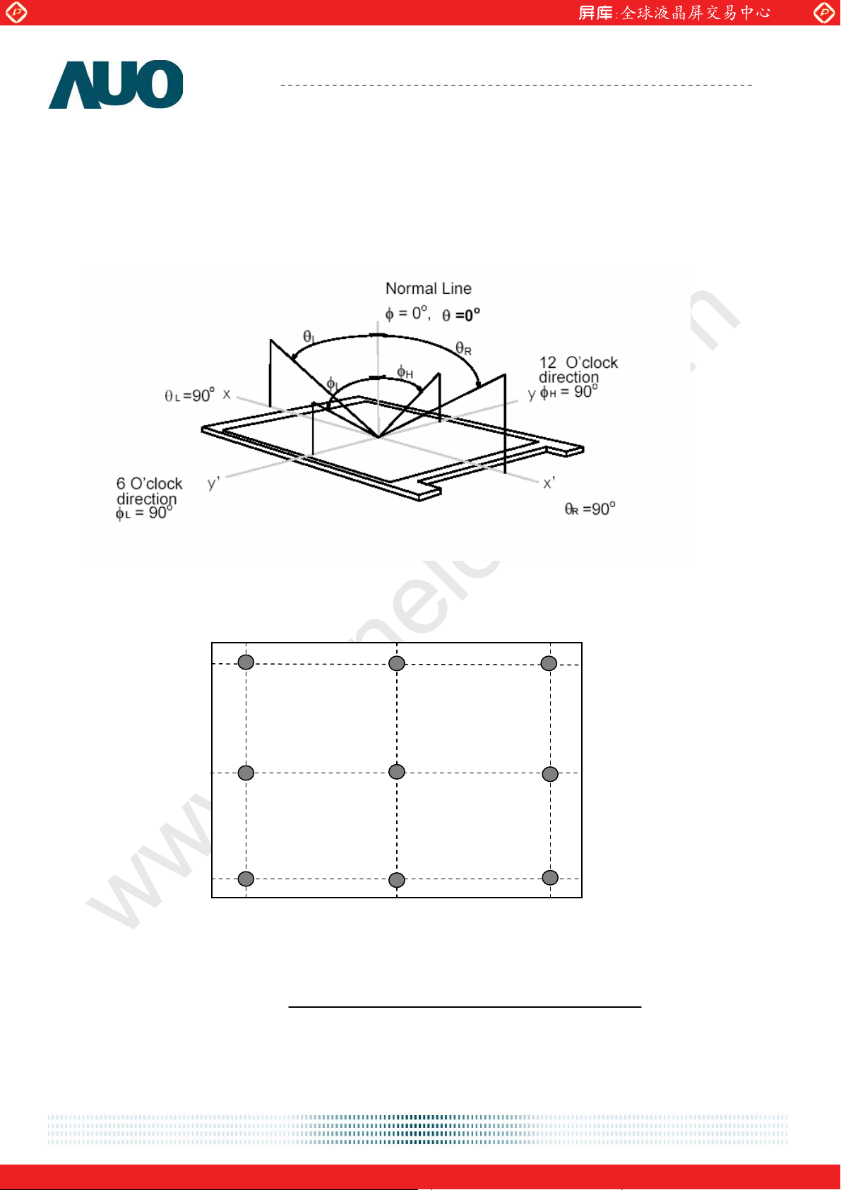
Note 1: Definition of viewing angle
Viewing angle is the measurement of contrast ratio Њ10, at the screen center, over a 180° horizontal and
180° vertical range (off-normal viewing angles). The 180° viewing angle range is broken down as follows;
90° (Ӱ) horizontal left and right and 90° (ӥ) vertical, high (up) and low (down). The measurement
direction is typically perpendicular to the display surface with the screen rotated about its center to
develop the desired measurement viewing angle.
AU OPTRONICS CORPORATION
M201SP01 V1
Note 2: 9 points position
90 %
50 %
10 %
10 %
50 %
90 %
Note 3: The luminance uniformity of 9 points is defined by dividing the maximum luminance values by the
minimum test point luminance
document version 0.1 7/34
One step solution for LCD / PDP / OLED panel application: Datasheet, inventory and accessory!
Ӭ
W9
Minimum Luminance of 9 points
=
Maximum Luminance of 9 points
www.panelook.com
Page 8
Global LCD Panel Exchange Center
www.panelook.com
Product Specification
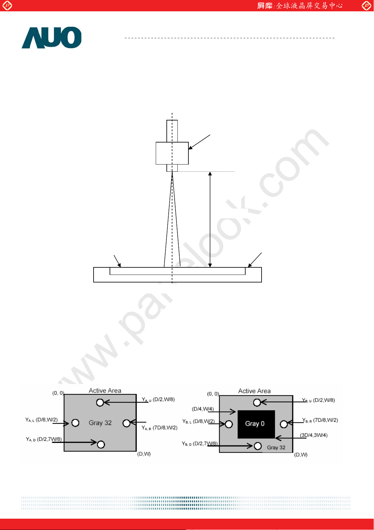
Note 4: Measurement method
The LCD module should be stabilized at given temperature for 30 minutes to avoid abrupt temperature
change during measuring. In order to stabilize the luminance, the measurement should be executed after
lighting Backlight for 30 minutes in a stable, windless and dark room. ʳ
AU OPTRONICS CORPORATION
M201SP01 V1
Photo detector
Field=2
50 cm
Note 5: Definition of Cross Talk (CT)
CT = | YB – YA | / YA Ø 100 (%)
Where
YA = Luminance of measured location without gray level 0 pattern (cd/m2)
YB = Luminance of measured location with gray level 0 pattern (cd/m2)
LCD Panel
Center of the screen
TFT-LCD Module
document version 0.1 8/34
One step solution for LCD / PDP / OLED panel application: Datasheet, inventory and accessory!
www.panelook.com
Page 9
Global LCD Panel Exchange Center
www.panelook.com
Product Specification
AU OPTRONICS CORPORATION
M201SP01 V1
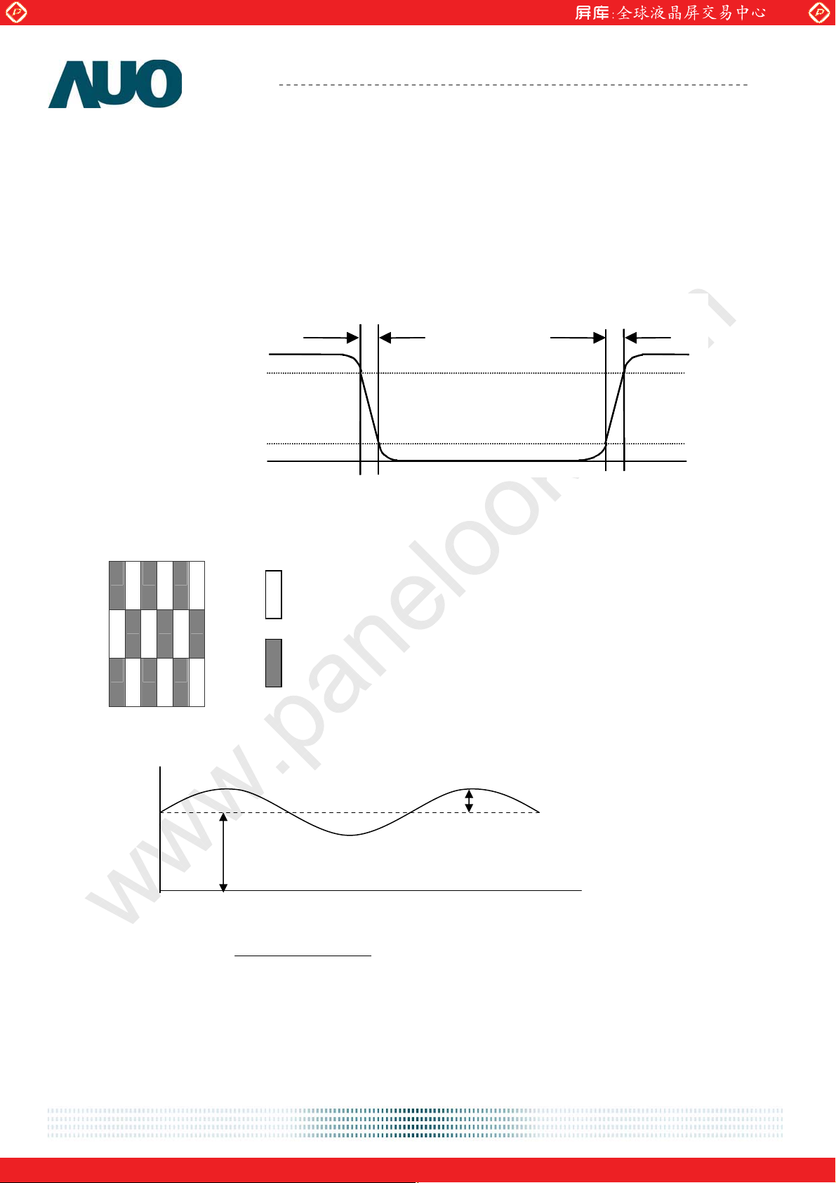
Note 6: Definition of response time:
The output signals of photo detector are measured when the input signals are changed from “Full Black” to
“Full White” (rising time), and from “Full White” to “Full Black ”(falling time), respectively. The response time
is interval between the 10% and 90% of amplitudes. Please refer to the figure as below.
%
Optical
Optical
response
response
100
100
90
90
10
10
%
White Black White
White Black White
0
0
Tr
Tr
Tr
Tr
R
F
F
R
Note 7: Subchecker Pattern
R G B R G B
Gray Level = L127
R G B R G B
R G B R G B
Gray Level = L0
Method: Record dBV & DC value with (WESTAR)TRD-100
Amplitude
AC
DC
Time
Hz) 30Level(at AC
log20(dB)Flicker
Level DC
document version 0.1 9/34
One step solution for LCD / PDP / OLED panel application: Datasheet, inventory and accessory!
www.panelook.com
Page 10
Global LCD Panel Exchange Center
www.panelook.com
Product Specification
AU OPTRONICS CORPORATION
M201SP01 V1
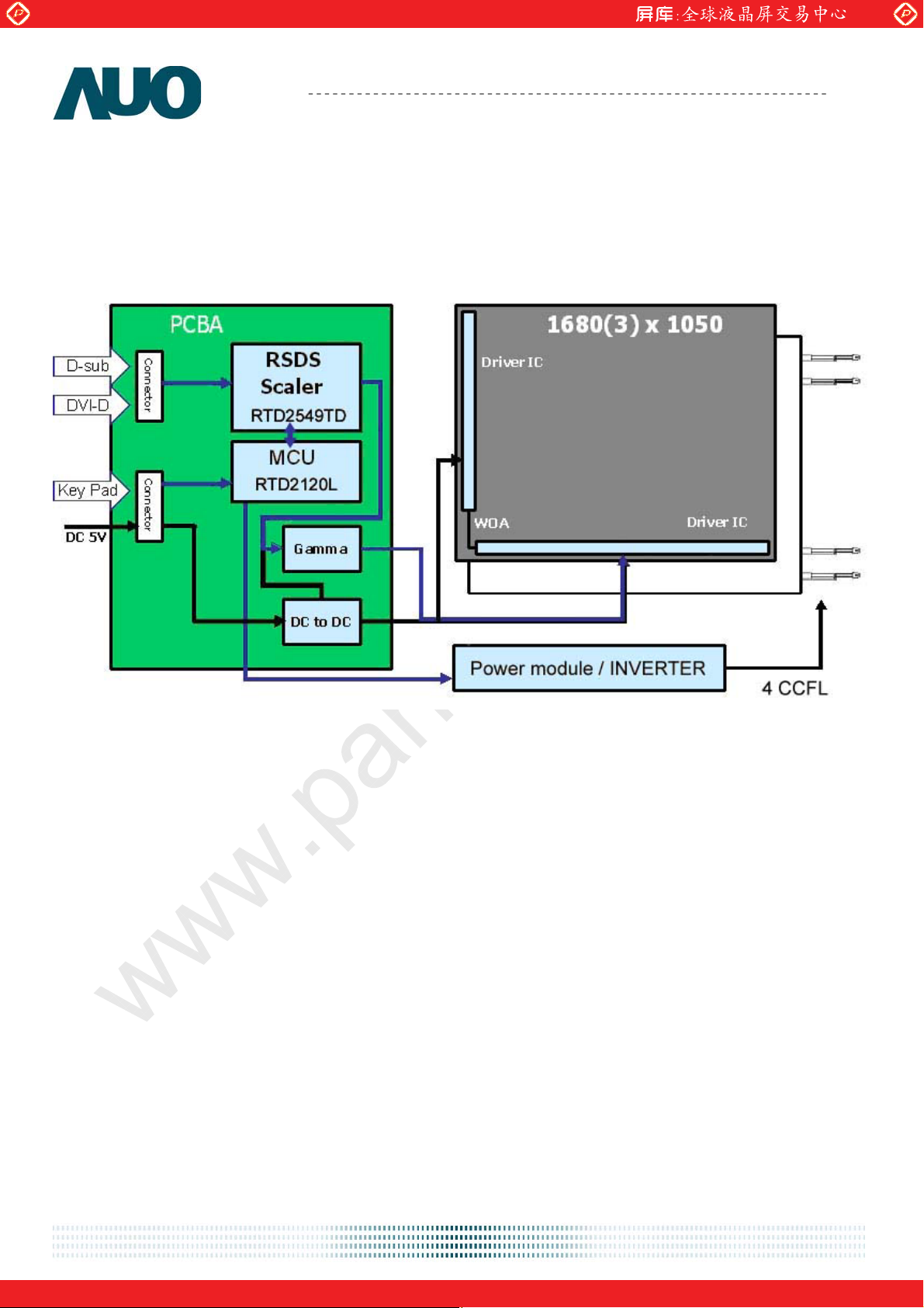
3. Functional Block Diagram
The following diagram shows the functional block of the 20.1 inches wide Color TFT-LCD Module:
document version 0.1 10/34
One step solution for LCD / PDP / OLED panel application: Datasheet, inventory and accessory!
www.panelook.com
Page 11
Global LCD Panel Exchange Center
g
www.panelook.com
Product Specification
AU OPTRONICS CORPORATION
M201SP01 V1
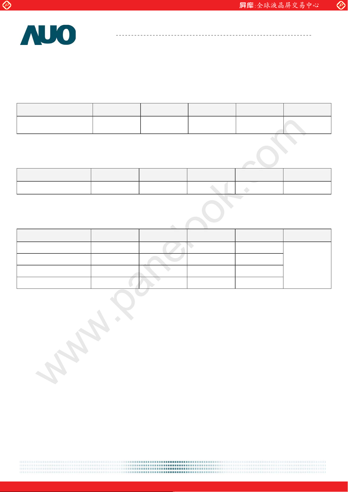
4. Absolute Maximum Ratings
Absolute maximum ratings of the module is as following:
4.1 Absolute Ratings of TFT LCD Module
Item Symbol Min. Max. Unit Conditions
Logic/LCD Drive
Volta
e
VCC -0.3 +5.25 [Volt] Note 1, 2
4.2 Absolute Ratings of Backlight Unit
Item Symbol Min. Max. Unit Conditions
CCFL Current ICFL 0 8.0 [mA] rms Note 1, 2
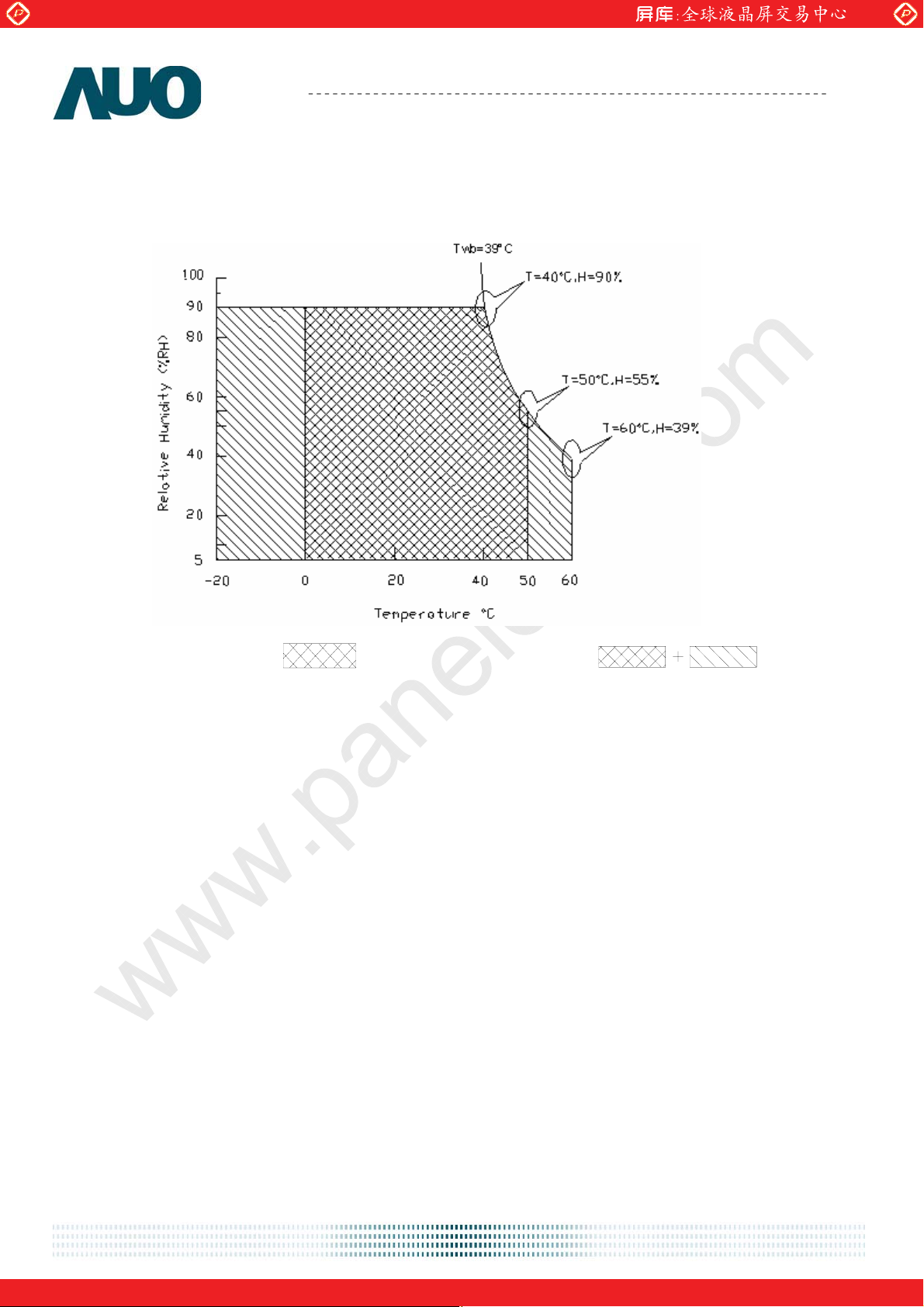
4.3 Absolute Ratings of Environment
Item Symbol Min. Max. Unit Conditions
Operating Temperature TOP 0 +50 [oC]
Operation Humidity HOP 5 90 [%RH]
Storage Temperature TST -20 +60 [oC]
Storage Humidity HST
5 90
[%RH]
Note 3
document version 0.1 11/34
One step solution for LCD / PDP / OLED panel application: Datasheet, inventory and accessory!
www.panelook.com
Page 12
Global LCD Panel Exchange Center
www.panelook.com
Product Specification
AU OPTRONICS CORPORATION
M201SP01 V1
Note 1: With in Ta= 25к
Note 2: Permanent damage to the device may occur if exceed maximum values
Note 3: For quality performance, please refer to AUO IIS (Incoming Inspection Standard).
Operating Range
Storage Range
document version 0.1 12/34
One step solution for LCD / PDP / OLED panel application: Datasheet, inventory and accessory!
www.panelook.com
Page 13
Global LCD Panel Exchange Center
www.panelook.com
Product Specification
AU OPTRONICS CORPORATION
M201SP01 V1
5. Electrical characteristics
5.1 TFT LCD Module
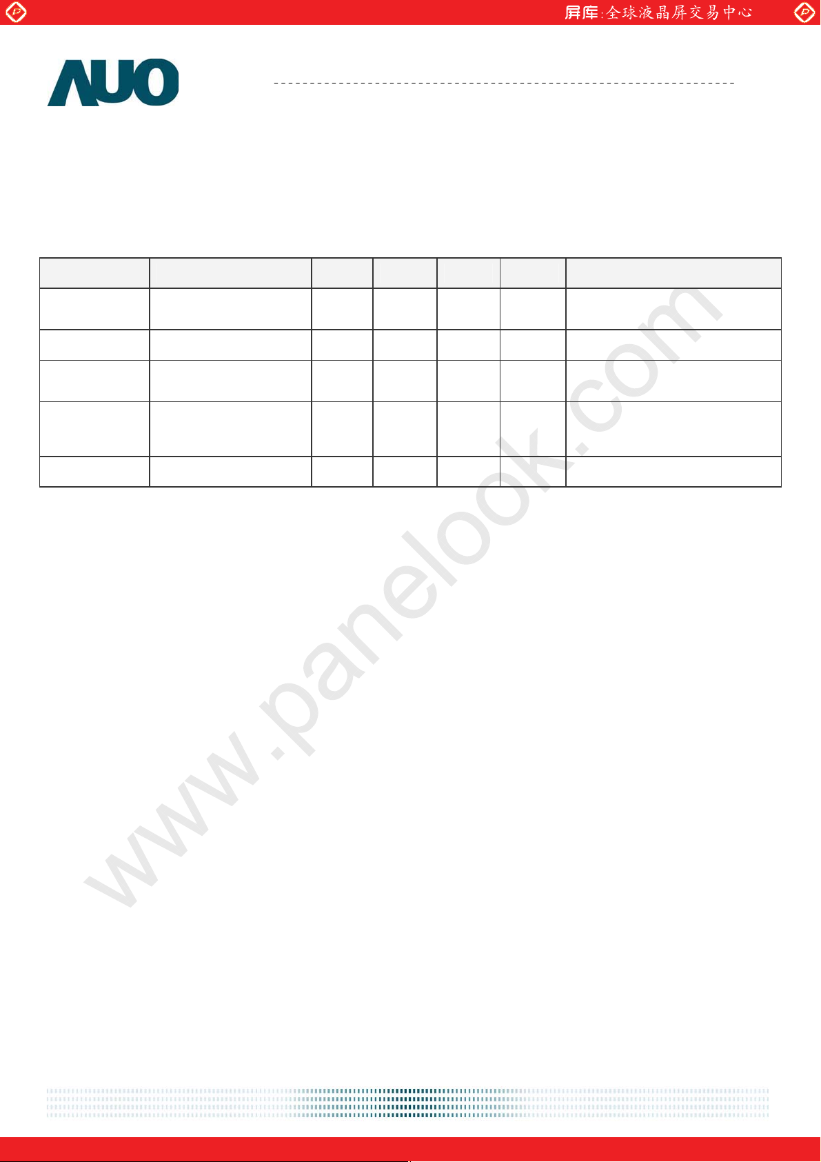
5.1.1 Power Specification
Input power specifications are as follows:
Symble Parameter Min. Typ. Max. Unit Condition
VCC
Logic/LCD Drive
Voltage
ICC Input Current - 1.3 1.6 [A] VCC= 5.0V, All Black Pattern
PCC VCC Power - 6.5 7.15 [Watt]
Allowable
VCCrp
Logic/LCD Drive
Ripple Voltage
4.75 5.0 5.25 [Volt] Load Capacitance 20uF
Note 1,
VCC= 5.0V, All Black Pattern
- - 100
[mV]
p-p
PS Power Saving - 0.3 0.5 [Watt] VCC= 5.0V
Note 1: The variance of VCC power consumption is ±10%.
document version 0.1 13/34
One step solution for LCD / PDP / OLED panel application: Datasheet, inventory and accessory!
www.panelook.com
Page 14
Global LCD Panel Exchange Center
www.panelook.com
Product Specification
AU OPTRONICS CORPORATION
M201SP01 V1
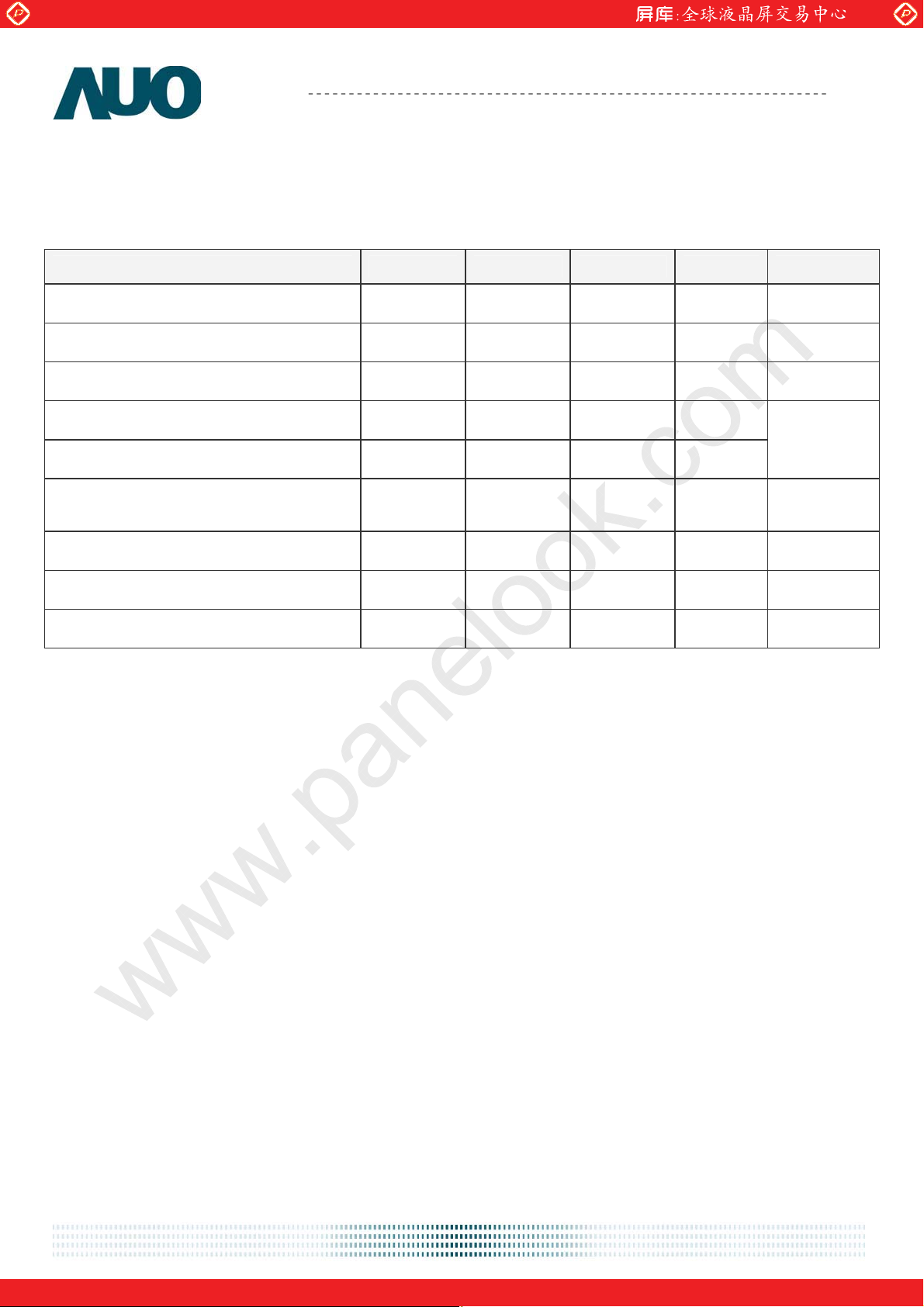
5.2 Backlight Unit
Parameter guideline for CCFL Inverter is under stable conditions at 25 (Room Temperature):к
Parameter Min.
CCFL Standard Current(ISCFL) 7.0 7.5 8.0 [mA] rms Note 2
CCFL Operation Current(IRCFL) 4.0 7.5 8.0 [mA] rms Note 2
CCFL Frequency(FCFL) 40 55 80 [KHz] Note 3,4
CCFL Ignition Voltage(ViCFL, Ta= 0 )к 1700 - - [Volt] rms
CCFL Ignition Voltage(ViCF, Ta= 25 )к 1300 - - [Volt] rms
CCFL Operation Voltage (VCFL) -
Typ. Max.
790
(@ 7.0mA)
920
(@3.0mA)
Unit Condition
Note 5
[Volt] rms Note 6
CCFL Power Consumption(PCFL) - 22.1 24.3 [Watt] Note 6
CCFL Life Time(LTCFL) 40,000 50,000 - [Hour] Note 7
PWM Dimming Ratio 20 100 % @7.5mA
Note 1: Typ. are AUO recommended design points.
*1 All of characteristics listed are measured under the condition using the AUO test inverter.
*2 In case of using an inverter other than listed, it is recommended to check the inverter carefully.
Sometimes, interfering noise stripes appear on the screen, and substandard luminance or flicker
at low power may happen.
*3 In designing an inverter, it is suggested to check safety circuit very carefully. Impedance of
CCFL, for instance, becomes more than 1 [M ohm] when CCFL is damaged.
*4 Generally, CCFL has some amount of delay time after applying kick-off voltage. It is
recommended to keep on applying kick-off voltage for 1 [Sec] until discharge.
*5 Reducing CCFL current increases CCFL discharge voltage and generally increases CCFL
discharge frequency. So all the parameters of an inverter should be carefully designed so as not
to produce too much leakage current from high-voltage output of the inverter.
Note 2: It should be employed the inverter which has “Duty Dimming”, if IRCFL is less than 4mA.
Note 3: CCFL discharge frequency should be carefully determined to avoid interference between inverter
and TFT LCD.
Note 4: The frequency range will not affect to lamp life and reliability characteristics.
Note 5: CCFL inverter should be able to give out a power that has a generating capacity of over 1,700
voltage. Lamp units need 1,700 voltage minimum for ignition.
Note 6: The variance of CCFL power consumption is ±10%. Calculator value for reference (ISCFL × VCFL ×
4 = PCFL)
Note 7: The definition of life time: Brightness becomes under 50%. The Typ. life time of CCFL is on the
condition at 7.5 mA lamp current.
document version 0.1 14/34
One step solution for LCD / PDP / OLED panel application: Datasheet, inventory and accessory!
www.panelook.com
Page 15
Global LCD Panel Exchange Center
www.panelook.com
Product Specification
6. Signal Characteristic
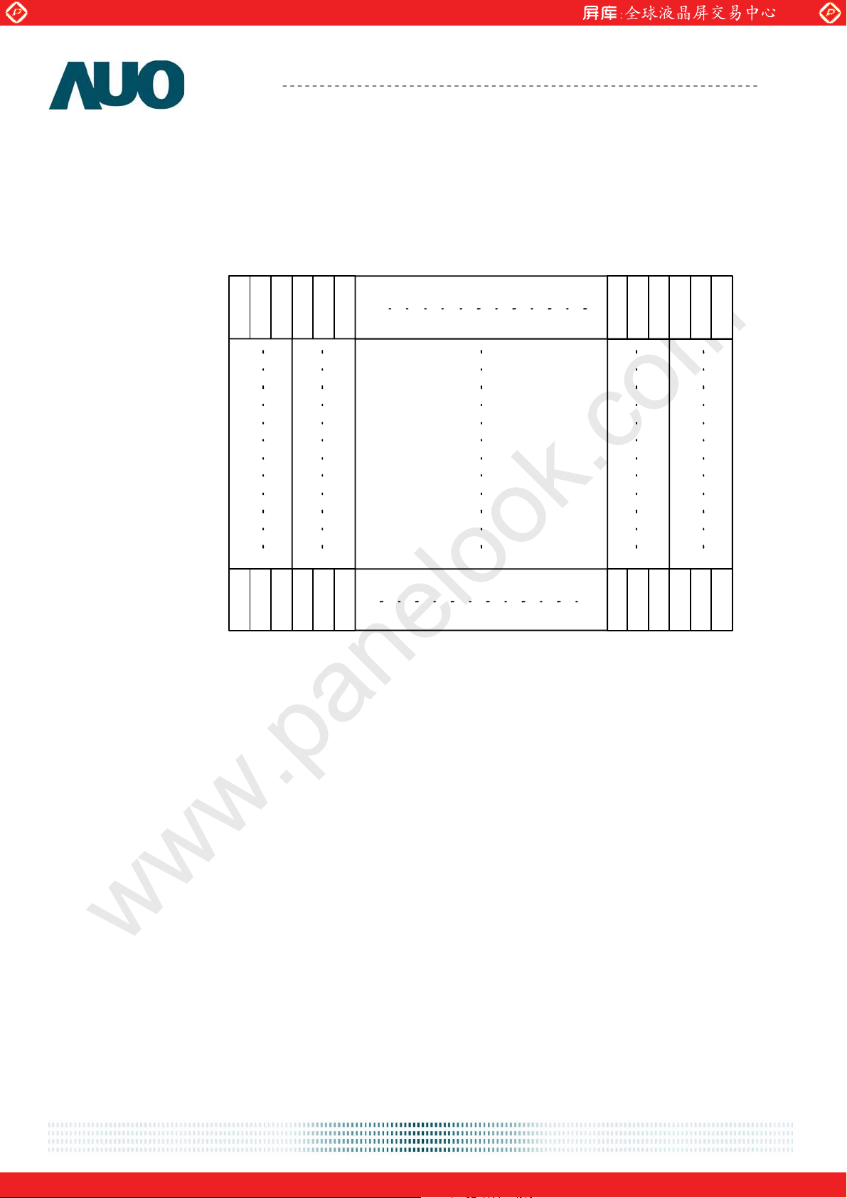
6.1 Pixel Format Image
Following figure shows the relationship of the input signals and LCD pixel format.
1st Line
R G B R G B
AU OPTRONICS CORPORATION
1 2 1679 1680
M201SP01 V1
R G B R G B
1050th Line
R G B R G B
R G B R G B
document version 0.1 15/34
One step solution for LCD / PDP / OLED panel application: Datasheet, inventory and accessory!
www.panelook.com
Page 16
Global LCD Panel Exchange Center
www.panelook.com
Product Specification
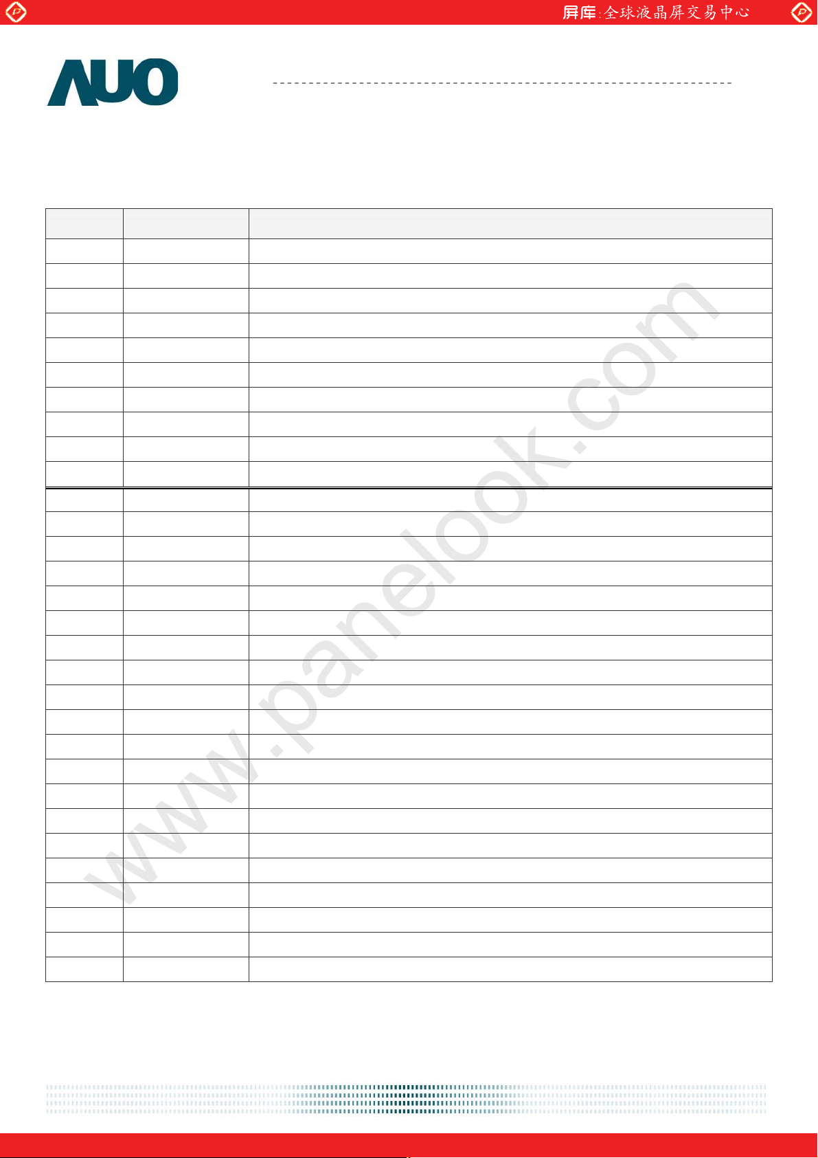
6.2 Signal Description
¾ Power / OSD Connector (J1)
PIN# Signal Name Description
1 VCC DC 5V
2 BKLT_ADJ Light adjust for the DC/AC inverter(PWM)
3 VCC DC 5V
4 BKLT_EN Enable for the DC/AC inverter
5 VCC DC 5V
6 AUDIO _EN Enable audio power control signal
7 VCC DC 5V
8 MUTE Mute audio
9 GND Ground
AU OPTRONICS CORPORATION
M201SP01 V1
10 VOLUME Adjust audio volume (PWM)
11 GND Ground
12 Key_Power Power on/off function
13 GND Ground
14 MENU OSD menu on/off function
15 GND Ground
16 PLUS OSD plus selection function
17 GND Ground
18 MINUS OSD minus selection function
19 NC No Connection
20 DOWN OSD down selection function
21 NC No Connection
22 UP OSD up selection function
23 NC No Connection
24 SELECT OSD item select function
25 NC No Connection
26 SOURCE OSD item source function
27 NC No Connection
28 LED_A LED Amber for the sleep mode
29 NC No Connection
30 LED_G LED Green for the full mode
document version 0.1 16/34
One step solution for LCD / PDP / OLED panel application: Datasheet, inventory and accessory!
www.panelook.com
Page 17
Global LCD Panel Exchange Center
www.panelook.com
Product Specification
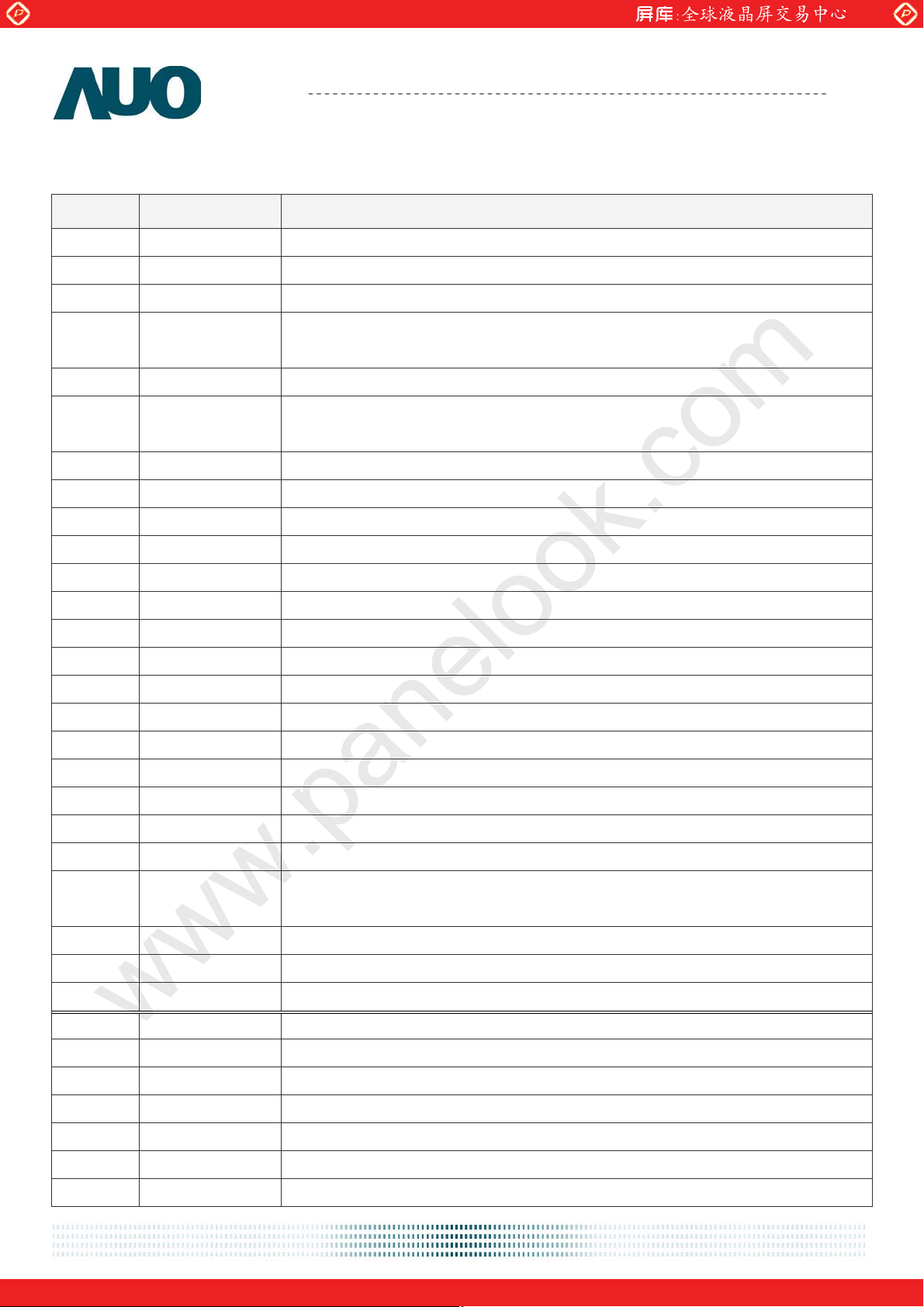
¾ DVI-D / D-sub Connector (J2)
PIN# Signal Name Description
1 DATA2/4 Shield Shared shield for TMDS link #0 channel #2 and link #1 channel #1
2 GND Ground
3 DATA2+ TMDS link #0 channel #2 differential pair
4 DVI_5V
5 DATA2- TMDS link #0 channel #2 differential pair
6 HPD
7 GND Ground
8 GND Ground
9 DATA1+ TMDS link #0 channel #1 differential pair
AU OPTRONICS CORPORATION
+5V signal provided by the system to enable the monitor to provide EDID
data when the monitor circuitry is not powered.
Host Plug Detect ; Signal is driven by monitor to enable the system to
identify the presence of a monitor.
M201SP01 V1
10 DDC Data The clock line for the DDC interface
11 DATA1- TMDS link #0 channel #1 differential pair
12 DDC Clock The data line for the DDC interface
13 DATA1/3 Shield Shared shield for TMDS link #0 channel #1 and link #1 channel #0
14 GND Ground
15 DATA0+ TMDS link #0 channel #0 differential pair
16 NC No Connection
17 DATA0- TMDS link #0 channel #0 differential pair
18 NC No Connection
19 DATA0/5 Shield Shared shield for TMDS link #0 channel #0 and link #1 channel #2
20 GND Ground
21 Clock+ TMDS clock differential pair
22 GND (for +5V)
Ground reference for +5V power pin. Used as return by HSync & VSync
signals.
23 Clock- TMDS clock differential pair
24 GND Ground
25 Clock Shield Shield for TMDS clock differential pair
26 VSync Vertical synchronization signal for the analog interface
27 B_GND Ground for the analog blue signal
28 HSync Horizontial synchronization signal for the analog interface
29 BIN Analog Blue signal
30 GND Ground
31 G_GND Ground for the analog green signal
32 SDA The data line for the DDC interface
document version 0.1 17/34
One step solution for LCD / PDP / OLED panel application: Datasheet, inventory and accessory!
www.panelook.com
Page 18
Global LCD Panel Exchange Center
www.panelook.com
Product Specification
AU OPTRONICS CORPORATION
M201SP01 V1
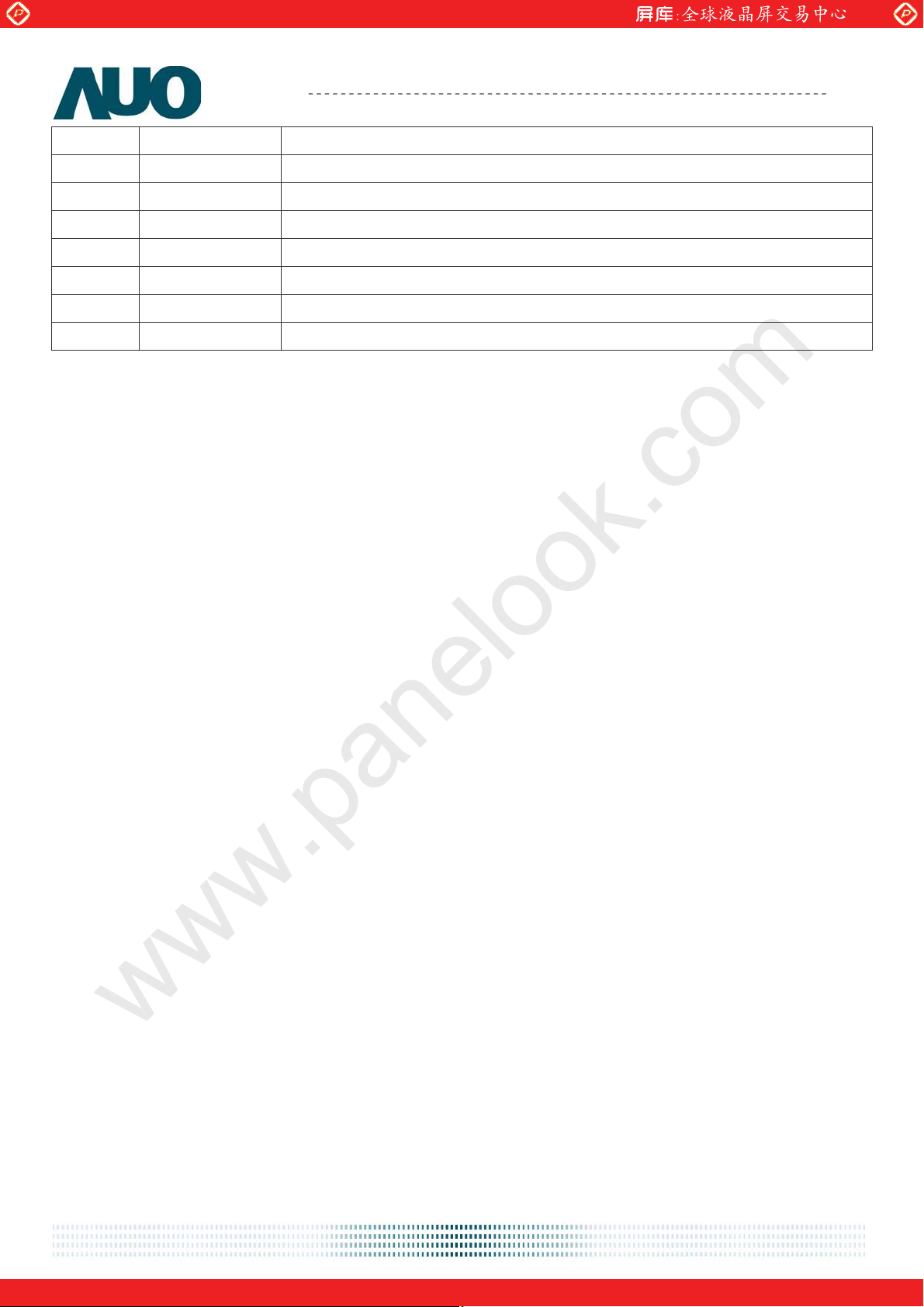
33 GIN Analog Green signal
34 SCL The clock line for the DDC interface
35 R_GND Ground for the analog red signal
36 PC_5V
+5V signal provided by the system to enable the monitor to provide EDID
37 RIN Analog Red signal
38 VGA_CON Video cable connected detect signal (host connect this pin to ground)
39 GND Ground
40 GND Ground
Note 1: For DVI-D cable part:
a. DVI differential pairs (DATA-/+) impedance 100+/-10 Ohm.
b. DVI differential pairs (DATA-/+) should twist wire.
Note 2: For D-sub cable part:
a. R/G/B impedance 75+/-10 Ohm
document version 0.1 18/34
One step solution for LCD / PDP / OLED panel application: Datasheet, inventory and accessory!
www.panelook.com
Page 19
Global LCD Panel Exchange Center
www.panelook.com
Product Specification
AU OPTRONICS CORPORATION
M201SP01 V1
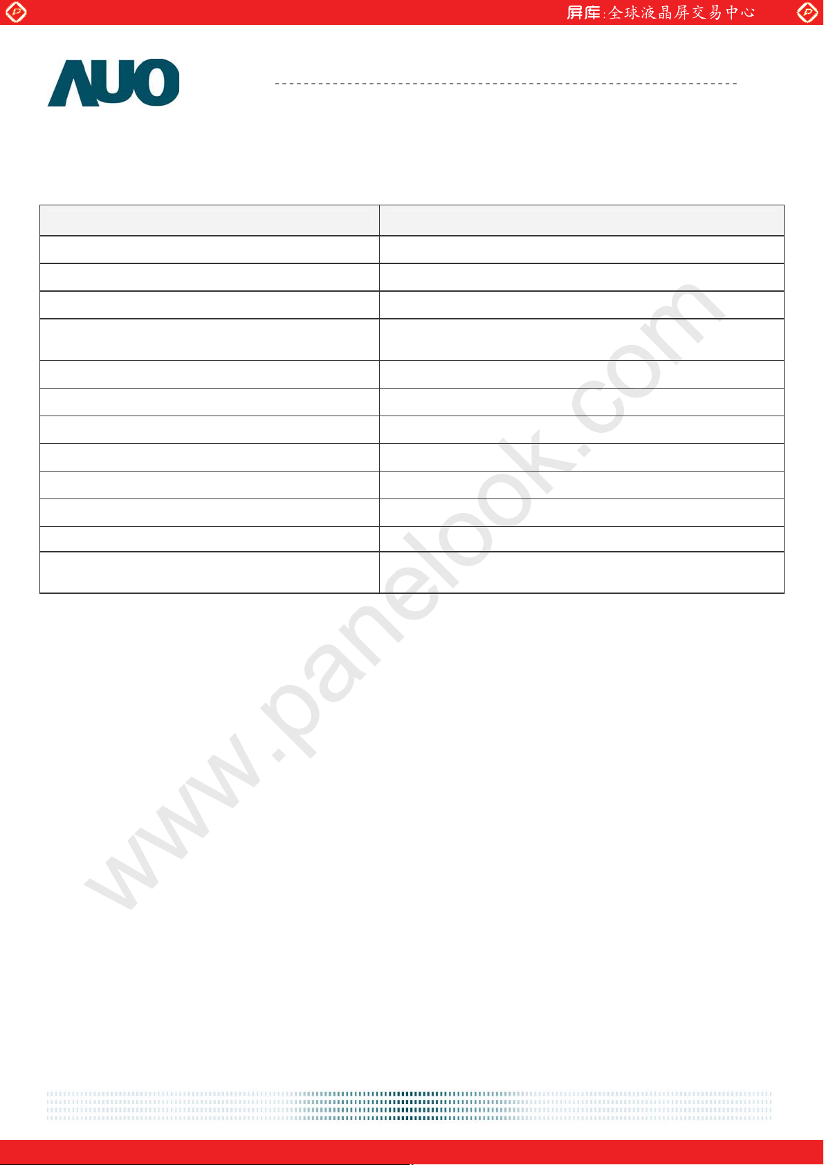
6.3 The input data format
The input data format is followed the VESA Vedio Signal Standard. In each RGB termination is described as
following table.
Values
Max Luminance Voltage Input Data = (FFh) 0.700 Volts +0.070 /-0.035 volts
Min Luminance voltage Input Data = (00h) 0.000 Volts
Video Channel Rise/Fall Time Max 25% of minimum pixel clock period
Maximum Settling Time after
overshoot/undershoot
Monotonic Yes
Resolution 1 LSB
Integral Linearity Error
Differential Linearity Errorʳ
30% of minimum pixel clock period averaged over 100
waveforms to 5% final full-scale value.
1 LSB
1 LSB
Video Channel to Video Channel Mismatch 6% of any video output voltage over the full voltage range
Video Noise injection ratio
2.5 % of Max Luminance Voltage
Video Channel to Video Channel Output Skew 50% of minimum pixel clock period
Overshoot/Undershoot
12% of step function voltage level over the full voltage
range
document version 0.1 19/34
One step solution for LCD / PDP / OLED panel application: Datasheet, inventory and accessory!
www.panelook.com
Page 20
Global LCD Panel Exchange Center
www.panelook.com
Product Specification
AU OPTRONICS CORPORATION
M201SP01 V1
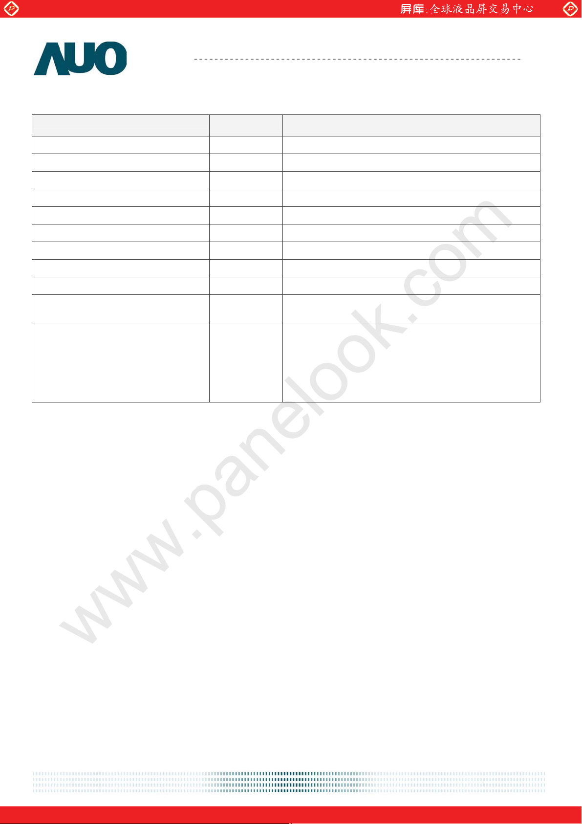
The Synchronization (Hsync and Vsync) Signal format is described as following table.
Min. Max.
Driver Logic Level “1” 2.4 Volts 5.5 Volts
Driver Logic Level “0” 0.0 Volts 0.5 Vots
Driver High Level Output Current 8mA
Driver Low Level Output Current 8mA
Receiver Logic Level “1” 2.0 Volts
Receiver Logic Level “0” 0.8 Volts
Fall Time Max 80% of minimum pixel clock period
Rise Time Max 80% of minimum pixel clock period
Monotonic Rise/Fall Voltage range 0.5-2.4 Volts
Overshoot/Undershoot
30% of high level signal voltage range No signal
excursions allowed in the 0.5-2.4 volt voltage range
Over the frequency spectrum: One half of the
difference between the maximum and minimum
Jitter
(Measured between Hsync pulses)
interval between Hsync pulses measured over
100,000 intervals shall be less than 15% of the pixel
clock, 0Hz to max. horizontal refresh rate at all image
formats, worst-case screen patterns.
LSB : Least Significant Bit
Monotonic
1. The property of either never increasing or never decreasing in reference to the slope of a
transient response.
2. A constant slope value containing no inflection points.
Sync: Synchronization Signals
For more details, please refer to VESA (Video Electronics Standards Association) Video Signal
Standard.
document version 0.1 20/34
One step solution for LCD / PDP / OLED panel application: Datasheet, inventory and accessory!
www.panelook.com
Page 21

Global LCD Panel Exchange Center
www.panelook.com
Product Specification
AU OPTRONICS CORPORATION
M201SP01 V1
6.4 Signal Electrical Characteristics
¾ Power / OSD interface (J1)
Pin# Name Type Min. Typ. Max. Unit Remark
1 VCC 4.75 5.0 5.25 V
2 BKLT_ADJ
High (Max.) VCC V
Low (Min.) 0.3 V
Internal serial 2.2K Ohm
Internal serial 3.2K Ohm
3 VCC 4.75 5.0 5.25 V
4 BKLT_EN
High (On) VCC V
Low (Off) 0.3 V
Internal serial 10K Ohm
5 VCC 4.75 5.0 5.25 V
6 AUDIO _EN
High (On) 2.65 3.3 V -4mA
Low (Off) GND 0.45 V 5mA
7 VCC 4.75 5.0 5.25 V
8 MUTE
High (On) 2.65 3.3 V -4mA
Low (Off) GND 0.45 V 5mA
9 GND
10 VOLUME
High (Max.) 3.2 V
Low (Min.) 0.1 V 4mA
11 GND
12 Key_Power Active 0 V
13 GND
14 MENU Active 0 V
15 GND
16 PLUS Active 0 V
17 GND
18 MINUS Active 0 V
19 NC
20 DOWN Active 0 V
21 NC
22 UP Active 0 V
23 NC
24 SELECT Active 0 V
25 NC
26 SOURCE Active 0 V
27 NC
28 LED_A
LED Amber for
the sleep mode
3.1 V Internal serial 68 Ohm
29 NC
30 LED_G
document version 0.1 21/34
LED Green for
the full mode
3.1 V Internal serial 68 Ohm
One step solution for LCD / PDP / OLED panel application: Datasheet, inventory and accessory!
www.panelook.com
Page 22
Global LCD Panel Exchange Center
www.panelook.com
Product Specification
AU OPTRONICS CORPORATION
M201SP01 V1
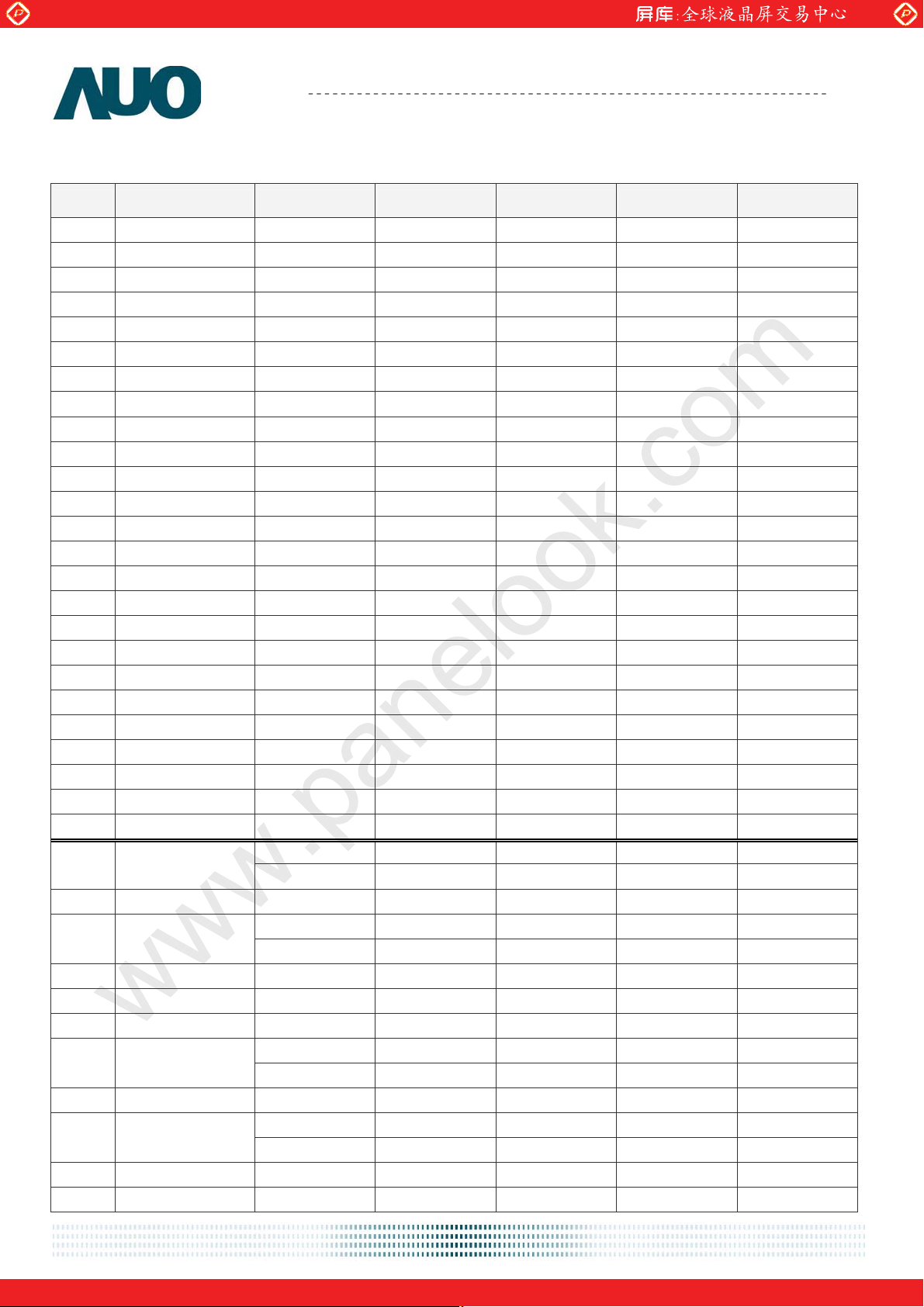
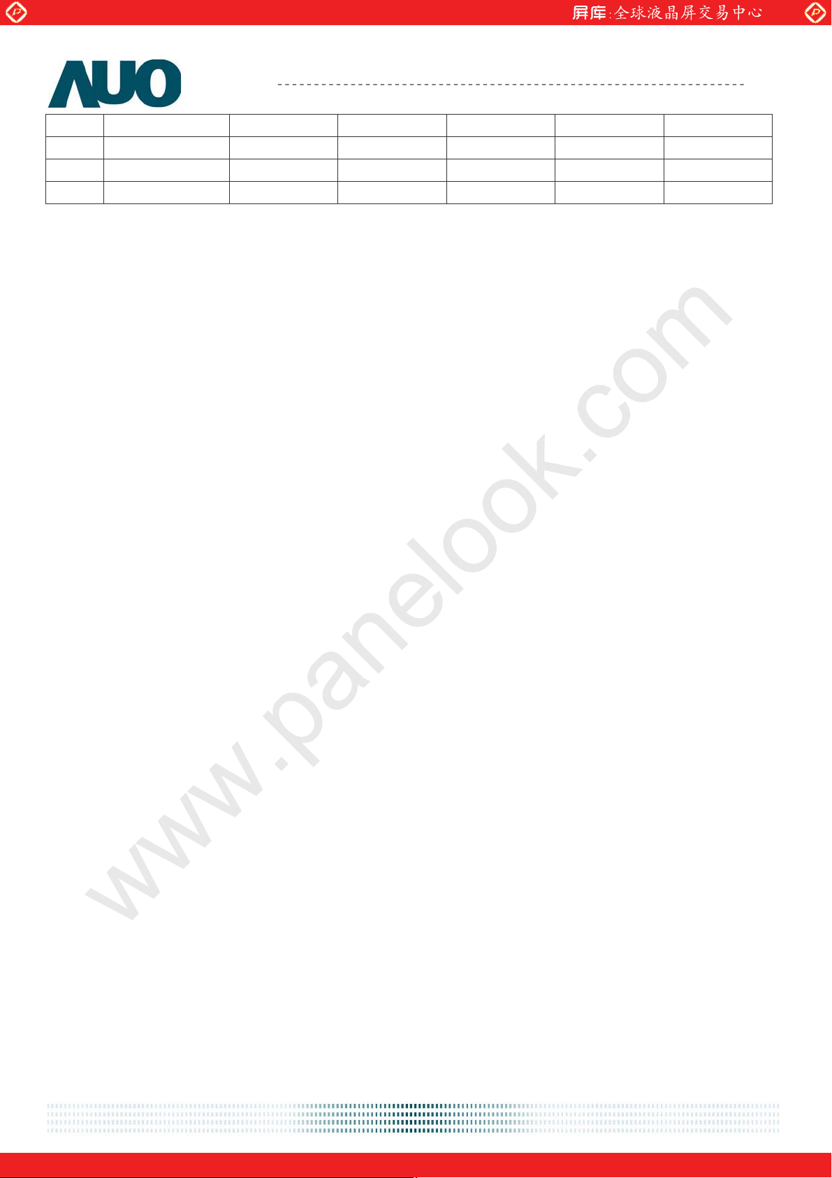
¾ DVI-D / D-sub interface (J2)
Pin# Name Type Min. Typ. Max. Unit
DATA2/4 Shield
1
2
3
4
5
6
7
8
9
10
11
12
13
14
15
16
17
18
19
20
21
22
23
24
25
GND
DATA2+
DVI_5V
DATA2-
HPD
GND
GND
DATA1+
DDC Data
DATA1-
DDC Clock
DATA1/3 Shield
GND
DATA0+
NC
DATA0-
NC
DATA0/5 Shield
GND
Clock+
DVI CON
Clock-
GND
Clock Shield
26
VSync
High 2.0 5.0 V
Low GND 0.8 V
27
28
B_GND
HSync
High 2.0 5.0 V
Low GND 0.8 V
29
30
31
32
BIN
GND
G_GND
SDA
700 mV
High 2.0 5.0 V
Low GND 0.8 V
33
34
GIN
SCL
700 mV
High 2.0 5.0 V
Low GND 0.8 V
35
36
document version 0.1 22/34
R_GND
PC_5V
One step solution for LCD / PDP / OLED panel application: Datasheet, inventory and accessory!
www.panelook.com
Page 23
Global LCD Panel Exchange Center
www.panelook.com
Product Specification
37
38
39
40
RIN
VGA_CON
GND
GND
AU OPTRONICS CORPORATION
700 mV
M201SP01 V1
document version 0.1 23/34
One step solution for LCD / PDP / OLED panel application: Datasheet, inventory and accessory!
www.panelook.com
Page 24
Global LCD Panel Exchange Center
www.panelook.com
Product Specification
AU OPTRONICS CORPORATION
M201SP01 V1
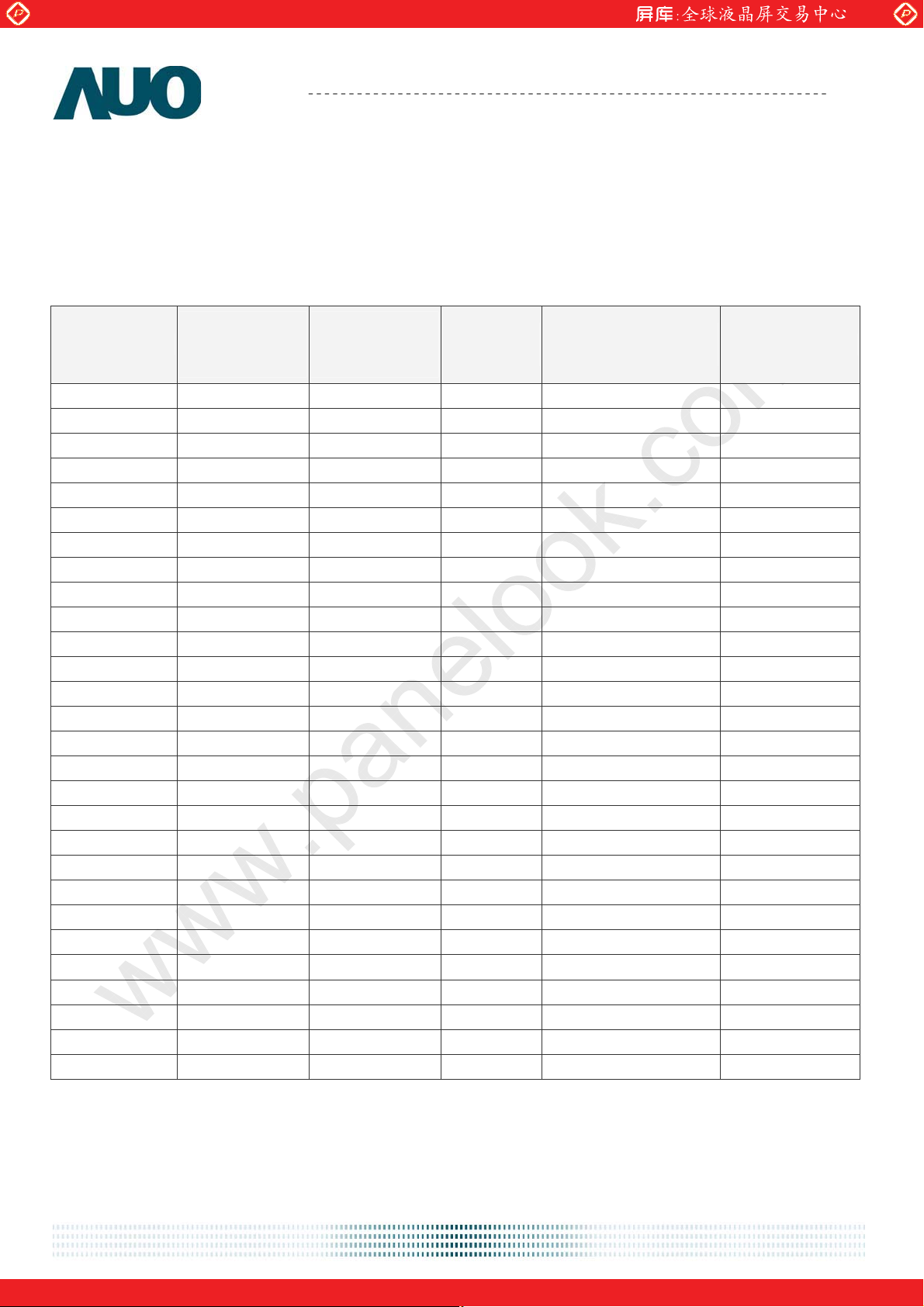
6.5 Interface Timings
The signal interface of the TFT-LCD module is analog RGB compatible.
6.5.1 Timing Characteristics
The timings are supported by the signal interface of M201SP01 are listed as following table.
Horizontal
Resolution
Frequency
(KHz)
640x350 31.47(P) 70.08(N) 25.17 1680 x1050 DOS
720x400 31.47(N) 70.08(P) 28.32 1680 x1050 DOS
640x480 31.47(N) 60.00(N) 25.18 1680 x1050 DOS
640x480 35.00(N) 67.00(N) 30.24 1680 x1050 Macintosh
640x480 37.86(N) 72.80(N) 31.5 1680 x1050 VESA
640x480 37.50(N) 75.00(N) 31.5 1680 x1050 VESA
800x600 37.88(P) 60.32(P) 40 1680 x1050 VESA
800x600 48.08(P) 72.19(P) 50 1680 x1050 VESA
800x600 46.86(P) 75.00(P) 49.5 1680 x1050 VESA
832X624 49.72(N) 74.55(N) 57.29 1680 x1050 Macintosh
1024x768 48.36(N) 60.00(N) 65 1680 x1050 VESA
1024x768 56.48(N) 70.10(N) 75 1680 x1050 VESA
1024x768 60.02(P) 75.00(P) 78.75 1680 x1050 VESA
1024X768 60.24(N) 74.93(N) 80 1680 x1050 Macintosh
1152x864 67.50(P) 75.00(P) 108 1680 x1050 VESA
1152x870 68.68(N) 75.06(N) 100 1680 x1050 Macintosh
1152x900 61.80(N) 66.00(N) 94.5 1680 x1050 SUN 66
1152x900 71.81(N) 76.14(N) 108 1680 x1050 SUN
1280x1024 64.00(P) 60.00(P) 108 1680 x1050 VESA
1280x1024 75.83(N) 71.53(N) 128 1680 x1050 IBM1
1280x1024 80.00(P) 75.00(P) 135 1680 x1050 VESA
1280x1024 81.18(N) 76.16(N) 135.09 1680 x1050 SPARC2
1680 x1050 64.7(P) 59.883(N) 119 1680 x1050 VESA
1680 x1050 65.29(N) 59.954(P) 146.25 1680 x1050 VESA
480p - - - 1680 x1050 HDMI/DVI
576p - - - 1680 x1050 HDMI/DVI
720p - - - 1680 x1050 HDMI/DVI
1080p - - - 1680 x1050 HDMI/DVI
Vertical
Frequency
(Hz)
Dot Clock
(MHz)
Actually Display
Resolution
Remark
Note-1: Depend on firmware setting. For D-sub, It can support other resolution when Dot Clock <210MHZ.
And DVI for Dot Clock <165MHZ
Note-2: “P”, “N” stands for “Positive”, “Negative” polarity of incoming H-sync/V-sync (input timing)
document version 0.1 24/34
One step solution for LCD / PDP / OLED panel application: Datasheet, inventory and accessory!
www.panelook.com
Page 25
Global LCD Panel Exchange Center
www.panelook.com
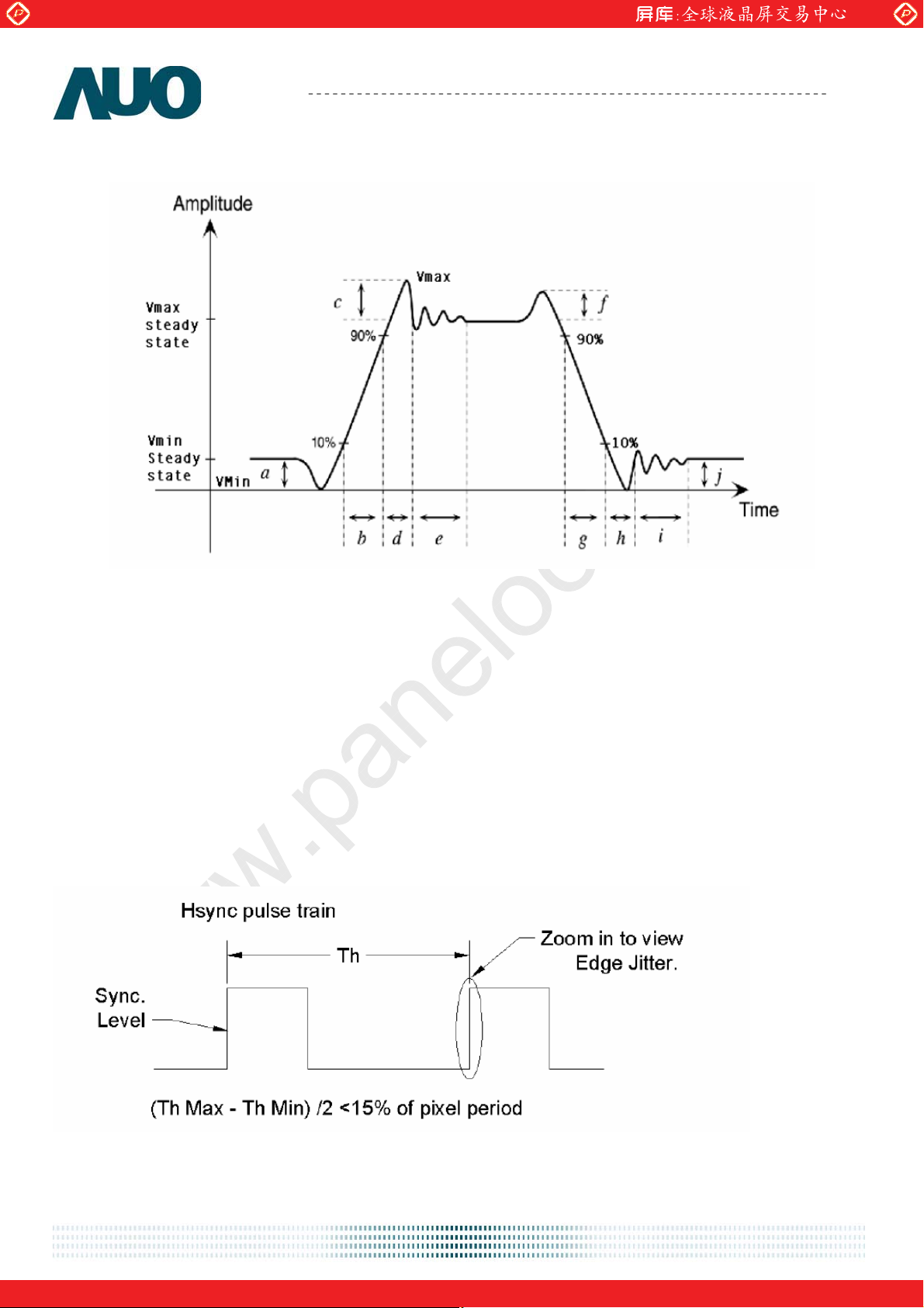
6.5.2 Definition of terms
¾ Video Signal Definition
Product Specification
AU OPTRONICS CORPORATION
M201SP01 V1
a) Vmin steady state Amplitude before transition
b) Video Rise Time Delta (t), (measured from the 10% to 90% points of Vmin Steady State to Vmax Steady
State)
c) Overshoot Amplitude
d) Undefined
e) Settling Time - Measured from the end of the overshoot to the point where the amplitude of the video
ringing is down to 5% of the final steady state value
f) Undefined
g) Video Fall Time Delta (t), (measured from the 90% to 10% points of Vmax Steady State to Vmin Steady
State)
h) Undefined here, Note: Undershoot is within this period and with an Amplitude of (j)
i) Settling Time - Measured from the end of the undershoot to the point where the amplitude of the video
ringing is down to 5% of the final steady state value
j) Vmin steady state Amplitude after transition
¾ Synchronization Signal Definition
document version 0.1 25/34
One step solution for LCD / PDP / OLED panel application: Datasheet, inventory and accessory!
www.panelook.com
Page 26
Global LCD Panel Exchange Center
www.panelook.com
Product Specification
AU OPTRONICS CORPORATION
M201SP01 V1
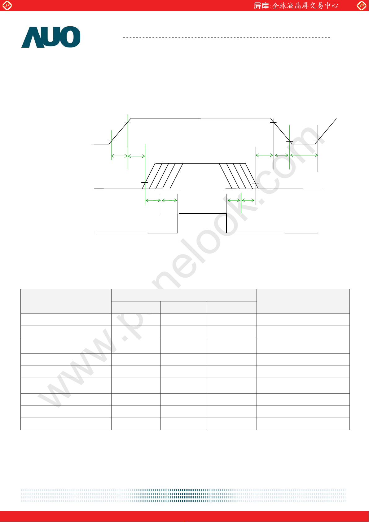
6.6 Power ON/OFF Sequence
VCC power and lamp on/off sequence is as follows. Interface signals are also shown in the chart. Signals
from any system shall be Hi-Z state or low level when VCC is off.
90%
Power Supply VCC
Input Signal
10%
T1
T2
VALID
DATA
T3
T4
T5
T6
T7
90%
T8
10%
T9
10%
Backlight On
Parameter
(Black pattern only)
(White pattern only)
Power Sequence Timing
Value
Unit
Min. Typ. Max.
T1 - - 10 [ms]
T2 10 - 50 [ms]
T3
T4 200 - - [ms]
T5 200 - - [ms]
T6
T7 0 16 50 [ms]
30 - 50 [ms]
50 - 100 [ms]
T8 - - 100 [ms]
T9 1000 - - [ms]
document version 0.1 26/34
One step solution for LCD / PDP / OLED panel application: Datasheet, inventory and accessory!
www.panelook.com
Page 27
Global LCD Panel Exchange Center
www.panelook.com
Product Specification
AU OPTRONICS CORPORATION
M201SP01 V1
7. Connector & Pin Assignment
Physical interface is described as for the connector on module.These connectors are capable of
accommodating the following signals and will be following components
.
7.1 TFT LCD Module
7.1.1 Connector
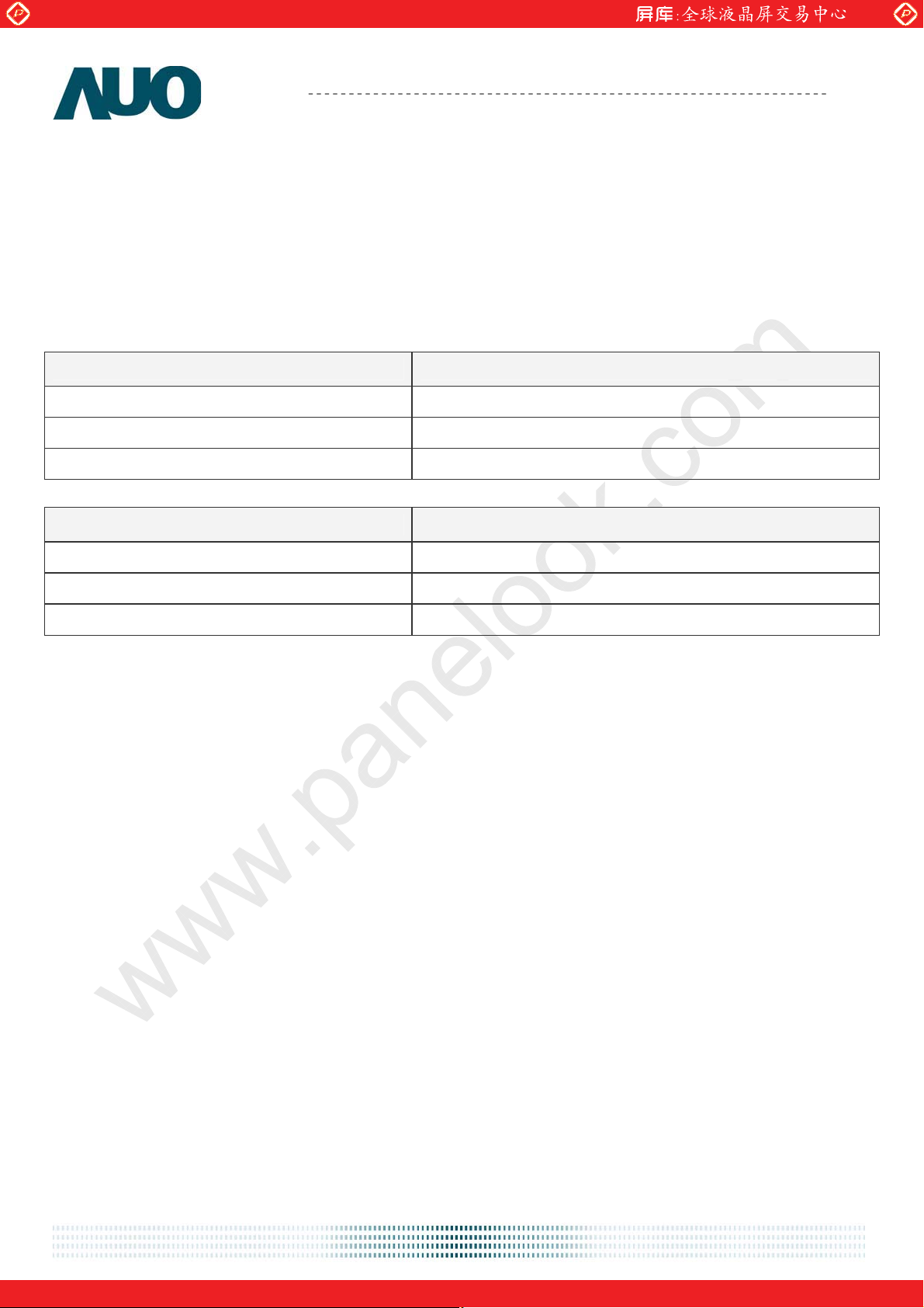
Connector Name / Designation Power / OSD Connector / J1
Manufacturer STM or compatiable
Type / Part Number STM-MDS240315A
Mating Housing / Part Number STM-PD240315
Connector Name / Designation DVI-D / D-sub Connector / J2
Manufacturer STM or compatiable
Type / Part Number STM-MDS240320A
Mating Housing / Part Number STM-PD24320-2
document version 0.1 27/34
One step solution for LCD / PDP / OLED panel application: Datasheet, inventory and accessory!
www.panelook.com
Page 28
Global LCD Panel Exchange Center
www.panelook.com
Product Specification
AU OPTRONICS CORPORATION
M201SP01 V1
7.1.2 Pin Assignment
¾ Power / OSD Connector (J1)
Pin# Signal Name Pin# Signal Name
1 VCC 2 BKLT_ADJ
3 VCC 4 BKLT_EN
5 VCC 6 AUDIO _EN
7 VCC 8 MUTE
9 GND 10 VOLUME
11 GND 12 Key_Power
13 GND 14 MENU
15 GND 16 PLUS
17 GND 18 MINUS
19 NC 20 DOWN
21 NC 22 UP
23 NC 24 SELECT
25 NC 26 SOURCE
27 NC 28 LED_A
29 NC 30 LED_G
document version 0.1 28/34
One step solution for LCD / PDP / OLED panel application: Datasheet, inventory and accessory!
www.panelook.com
Page 29
Global LCD Panel Exchange Center
www.panelook.com
Product Specification
AU OPTRONICS CORPORATION
M201SP01 V1
¾ DVI-D / D-sub Connector (J2)
Pin# Signal Name Pin# Signal Name
1 DATA2/4 Shield 2 GND
3 DATA2+ 4 DVI_5V
5 DATA2- 6 HPD
7 GND 8 GND
9 DATA1+ 10 DDC Data
11 DATA1- 12 DDC Clock
13 DATA1/3 Shield 14 GND
15 DATA0+ 16 NC
17 DATA0- 18 NC
19 DATA0/5 Shield 20 GND
21 Clock+ 22 GND (for +5V)
23 Clock- 24 GND
25 Clock Shield 26 VSync
27 B_GND 28 HSync
29 BIN 30 GND
31 G_GND 32 SDA
33 GIN 34 SCL
35 R_GND 36 PC_5V
37 RIN 38 VGA_CON
39 GND 40 GND
document version 0.1 29/34
One step solution for LCD / PDP / OLED panel application: Datasheet, inventory and accessory!
www.panelook.com
Page 30
Global LCD Panel Exchange Center
www.panelook.com
Product Specification
AU OPTRONICS CORPORATION
M201SP01 V1
7.2 Backlight Unit
Physical interface is described as for the connector on module. These connectors are capable of
accommodating the following signals and will be following components.
Connector Name / Designation Lamp Connector / Backlight Lamp
Manufacturer YEONHO or compatiable
Type / Part Number 35001TS-L
Mating Type / Part Number 35001HS-02L
7.2.1 Signal for Lamp connector
Pin # Cable color Signal Name
1 Pink High Voltage
2 Black Low Voltage
Upper
3 Blue High Voltage
4 Dark Blue Low Voltage
Pin # Cable color Signal Name
1 Pink High Voltage
2 Black Low Voltage
Lower
3 Blue High Voltage
4 Dark Blue Low Voltage
document version 0.1 30/34
One step solution for LCD / PDP / OLED panel application: Datasheet, inventory and accessory!
www.panelook.com
Page 31
Global LCD Panel Exchange Center
www.panelook.com
Product Specification
8. Reliability Test
Environment test conditions are listed as following table.
Items Required Condition
Temperature Humidity Bias (THB) Ta= 50 , к 80%RH, 300hours
High Temperature Operation (HTO) Ta= 50 , к 50%RH, 300hours
Low Temperature Operation (LTO) Ta= 0 , 300hoursк
High Temperature Storage (HTS) Ta= 60 , 300hoursк
Low Temperature Storage (LTS) Ta= -20 , 300hoursк
Vibration Test
(Non-operation)
Shock Test
(Non-operation)
AU OPTRONICS CORPORATION
Acceleration: 1.5 G
Wave: Random
Frequency: 10 - 200 - 10 Hz
Sweep: 30 Minutes each Axis (X, Y, Z)
Acceleration: 50 G
Wave: Half-sine
Active Time: 20 ms
Direction: X,ʳY,ʳZ (one time for each Axis)
M201SP01 V1
Note
Drop Test Height: 60 cm, package test
Thermal Shock Test (TST) -20к/30min, 60к/30min, 100 cycles
On/Off Test On/10sec, Off/10sec, 30,000 cycles
Contact Discharge: ± 8KV, 150pF(330 ) 1sec,
8 points, 25 times/ point.
ESD (ElectroStatic Discharge)
Air Discharge: ± 15KV, 150pF(330 ) 1sec
8 points, 25 times/ point.
Altitude Test
Note 1: The TFT-LCD module will not sustain damage after being subjected to 100 cycles of rapid
temperature change. A cycle of rapid temperature change consists of varying the temperature from
-2˃к to 6˃к, and back again. Power is not applied during the test. After temperature cycling, the
unit is placed in normal room ambient for at least 4 hours before power on.
Note 2: According to EN61000-4-2 , ESD class B: Some performance degradation allowed. No data lost.
Self-recoverable. No hardware failures.
Operation:10,000 ft
Non-Operation:30,000 ft
1
2
document version 0.1 31/34
One step solution for LCD / PDP / OLED panel application: Datasheet, inventory and accessory!
www.panelook.com
Page 32
Global LCD Panel Exchange Center
www.panelook.com
Product Specification
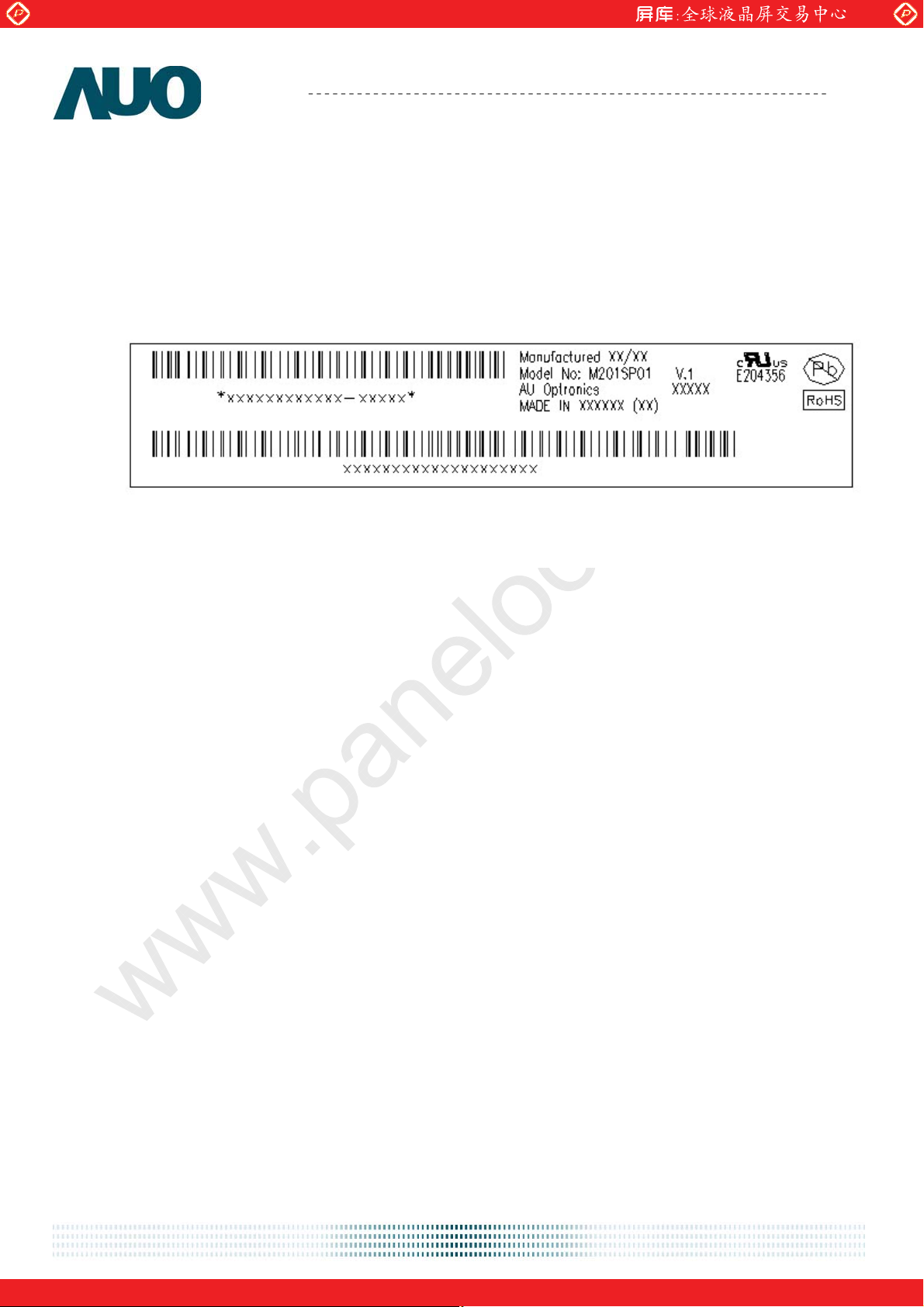
9. Shipping Label
The shipping label format is shown as below.
AU OPTRONICS CORPORATION
M201SP01 V1
document version 0.1 32/34
One step solution for LCD / PDP / OLED panel application: Datasheet, inventory and accessory!
www.panelook.com
Page 33
Global LCD Panel Exchange Center
www.panelook.com
Product Specification
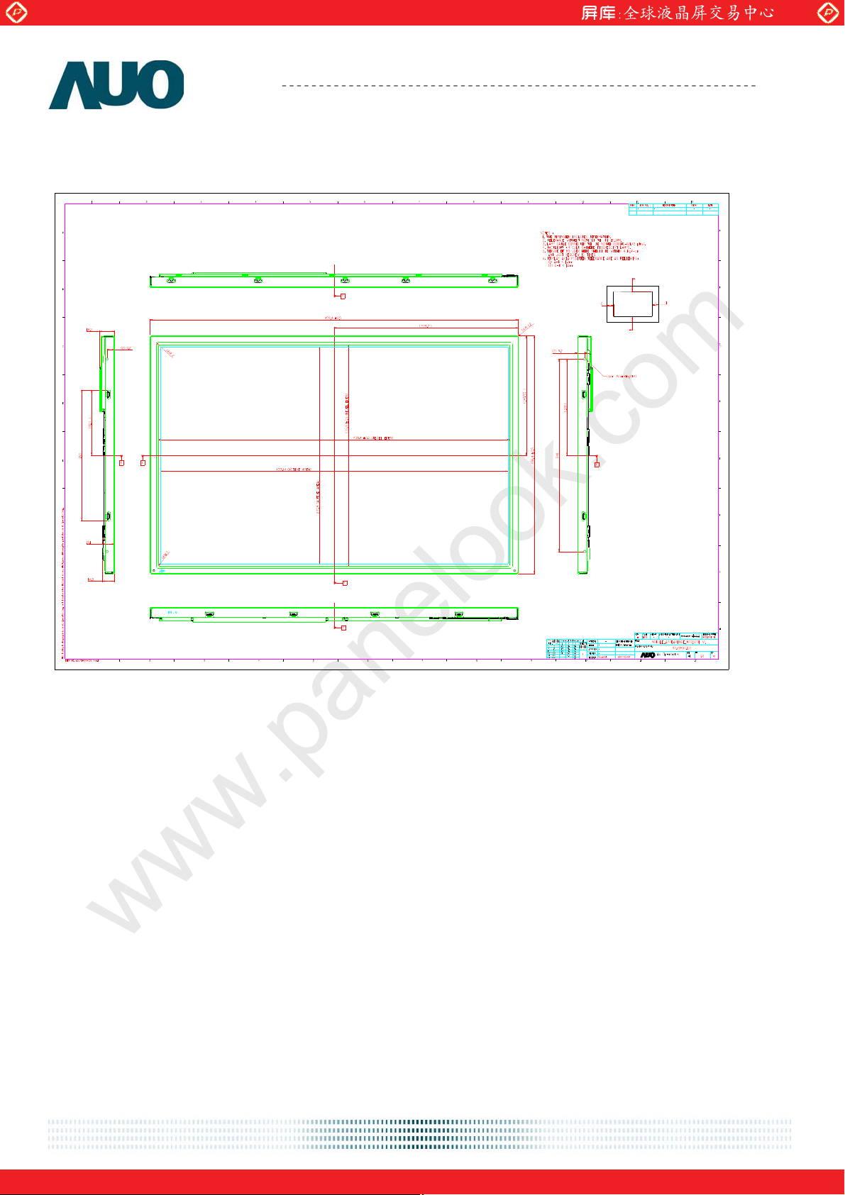
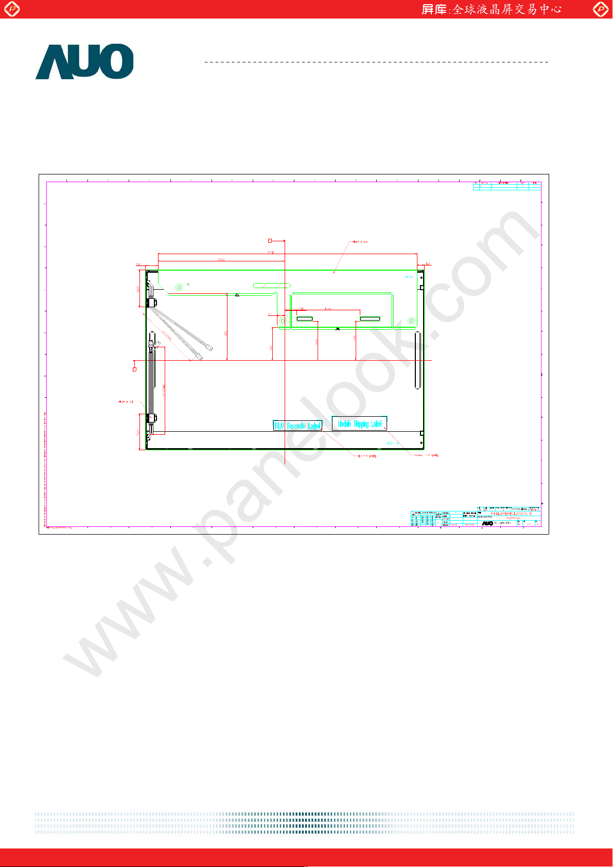
10. Mechanical Characteristics
AU OPTRONICS CORPORATION
M201SP01 V1
document version 0.1 33/34
One step solution for LCD / PDP / OLED panel application: Datasheet, inventory and accessory!
www.panelook.com
Page 34
Global LCD Panel Exchange Center
www.panelook.com
Product Specification
AU OPTRONICS CORPORATION
M201SP01 V1
document version 0.1 34/34
One step solution for LCD / PDP / OLED panel application: Datasheet, inventory and accessory!
www.panelook.com
 Loading...