

Page 1
Global LCD Panel Exchange Center
www.panelook.com
Product Specification
AU OPTRONICS CORPORATION
M185XTN01.0
() Preliminary Specification
(V) Final Specification
Module
18.5” Color TFT-LCD
Model Name
M185XTN01.0
Customer Date
Approved by
Approved by Date
ChiYin Wu
Prepared by
2011/11/18
Note: This Specification is subject to
change without notice.
document version 1.0 1
One step solution for LCD / PDP / OLED panel application: Datasheet, inventory and accessory!
Derec Yang
Desktop Display Business Group /
AU Optronics corporation
2011/11/17
www.panelook.com
Page 2
Global LCD Panel Exchange Center
www.panelook.com
Product Specification
AU OPTRONICS CORPORATION
Contents
M185XTN01.0
1.0 Handling Precautions ............................................................ 4
2.0 General Description ............................................................... 5
2.1 Display Characteristics ...................................................................................................................5
2.2 Optical Characteristics ....................................................................................................................6
3.0 Functional Block Diagram .................................................... 10
4.0 Absolute Maximum Ratings......................................................... 11
4.1 TFT LCD Module .............................................................................................................................11
4.2 Backlight Unit ................................................................................................................................... 11
4.3 Absolute Ratings of Environment..................................................................................................... 11
5.0 Electrical characteristics...................................................... 12
5.1 TFT LCD Module............................................................................................................................ 12
5.1.1 Power Specification.............................................................................................. 12
5.1.2 Signal Electrical Characteristics .............................................................................. 13
5.2 Backlight Unit ...................................................................................................................................15
6.0 Signal Characteristic............................................................ 16
6.1 Pixel Format Image ....................................................................................................................... 16
6.2 The input data format ....................................................................................................................17
6.3 Signal Description.......................................................................................................................... 18
6.4 Timing Characteristics ......................................................................................................................20
6.5 Timing diagram............................................................................................................................... 21
6.6 Power ON/OFF Sequence ...........................................................................................................22
7.0 Connector & Pin Assignment ............................................... 23
7.1 TFT LCD Module............................................................................................................................ 23
7.1.1 LVDS Connector Pin Assignment............................................................................. 23
7.2 Recommend connector for Backlight Unit .......................................................................................24
7.2.1 Light Bar Connector Pin assignment ........................................................................ 24
7.2.2 Light Bar Connector Dimension .............................................................................. 24
8.0 Reliability Test..................................................................... 25
9.0 Shipping Label ..................................................................... 26
10.0 Mechanical Characteristics ................................................ 27
11. Packing Specification........................................................... 28
document version 1.0 2
One step solution for LCD / PDP / OLED panel application: Datasheet, inventory and accessory!
www.panelook.com
Page 3
Global LCD Panel Exchange Center
www.panelook.com
Version and
Date
0.1
2011/10/7
1.0
2011/10/7
Pag
All
All
e
Old description New Description Remark
First Edition for Customer
Preliminary)
(
First Edition for Customer
Product Specification
AU OPTRONICS CORPORATION
Record of Revision
N/A
N/A
M185XTN01.0
document version 1.0 3
One step solution for LCD / PDP / OLED panel application: Datasheet, inventory and accessory!
www.panelook.com
Page 4
Global LCD Panel Exchange Center
www.panelook.com
Product Specification
AU OPTRONICS CORPORATION
M185XTN01.0
1.0 Handling Precautions
1) Since front polarizer is easily damaged, pay attention not to scratch it.
2) Be sure to turn off power supply when inserting or disconnecting from input connector.
3) Wipe off water drop immediately. Long contact with water may cause discoloration or spots.
4) When the panel surface is soiled, wipe it with absorbent cotton or other soft cloth.
5) Since the panel is made of glass, it may break or crack if dropped or bumped on hard surface.
6) Since CMOS LSI is used in this module, take care of static electricity and insure human earth
when handling.
7) Do not open or modify the Module Assembly.
8) Do not press the reflector sheet at the back of the module to any directions.
9) In case if a Module has to be put back into the packing container slot after once it was taken
out from the container, do not press the center of the LED lightbar edge. Instead, press at the
far ends of the LED light bar edge softly. Otherwise the TFT Module may be damaged.
10) At the insertion or removal of the Signal Interface Connector, be sure not to rotate nor tilt the
Interface Connector of the TFT Module.
11) After installation of the TFT Module into an enclosure, do not twist nor bend the TFT Module
even momentary. At designing the enclosure, it should be taken into consideration that no
bending/twisting forces are applied to the TFT Module from outside. Otherwise the TFT
Module may be damaged.
12) Small amount of materials having no flammability grade is used in the LCD module. The LCD
module should be supplied by power complied with requirements of Limited Power Source
(IEC60950 or UL1950), or be applied exemption.
13) Please avoid touching COF position while you are doing mechanical design.
14) When storing modules as spares for a long time, the following precaution is necessary:
Store them in a dark place. Do not expose the module to sunlight or fluorescent light. Keep
the temperature between ˈкʳ ˴˷ʳˆˈкʳ ˴ʳ˴˿ʳ˻˼˷˼ˁ
document version 1.0 4
One step solution for LCD / PDP / OLED panel application: Datasheet, inventory and accessory!
www.panelook.com
Page 5
Global LCD Panel Exchange Center
www.panelook.com
Product Specification
AU OPTRONICS CORPORATION
M185XTN01.0
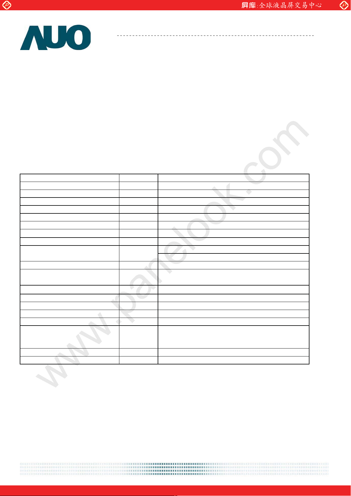
2.0 General Description
This specification applies to the 18.5 inch-wide Color a-Si TFT-LCD Module M185XW01.The
display supports the WXGA - 1366(H) x 768(V) screen format and 16.7M colors (RGB 6-bits +
Hi-FRC data). All input signals are 1-channel LVDS interface and this module doesn’t contain an
inverter board for backlight.
2.1 Display Characteristics
The following items are characteristics summary on the table under 25к condition:
ITEMS Unit SPECIFICATIONS
Screen Diagonal [mm]
Active Area [mm] 409.8 (H) x 230.4 (V)
Pixels H x V 1366(x3) x 768
Pixel Pitch [um] 300 (per one triad) × 300
Pixel Arrangement R.G.B. Vertical Stripe
Display Mode TN Mode, Normally White
White Luminance ( Center ) [cd/m2]
Contrast Ratio 700 (Typ.)
Optical Response Time [msec] 5ms (Typ., on/off)
Nominal Input Voltage VDD [Volt] +5.0 V (Typ)
Power Consumption
[Watt]
(VDD line + LED line)
Weight [Grams]
Physical Size [mm] 430.4 (W) x 254.6 (H) Typ. x 9.8 (D) Typ
Interface One channel LVDS
Support Color 16.7M colors (RGB 6-bit + Hi_FRC )
Surface Treatment Anti-Glare, 3H
Temperature Range
Operating
Storage (Shipping)
o
[
C]
o
[
C]
TCO5.1 Compliance N/A
RoHS Compliance RoHS Compliance
470.1(18.51”)
200 cd/m
2
(Typ.)
7.8 (Typ.)
(without inverter, all black pattern)
12907\S
0 to +50
-20 to +60
document version 1.0 5
One step solution for LCD / PDP / OLED panel application: Datasheet, inventory and accessory!
www.panelook.com
Page 6
Global LCD Panel Exchange Center
www.panelook.com
Product Specification
AU OPTRONICS CORPORATION
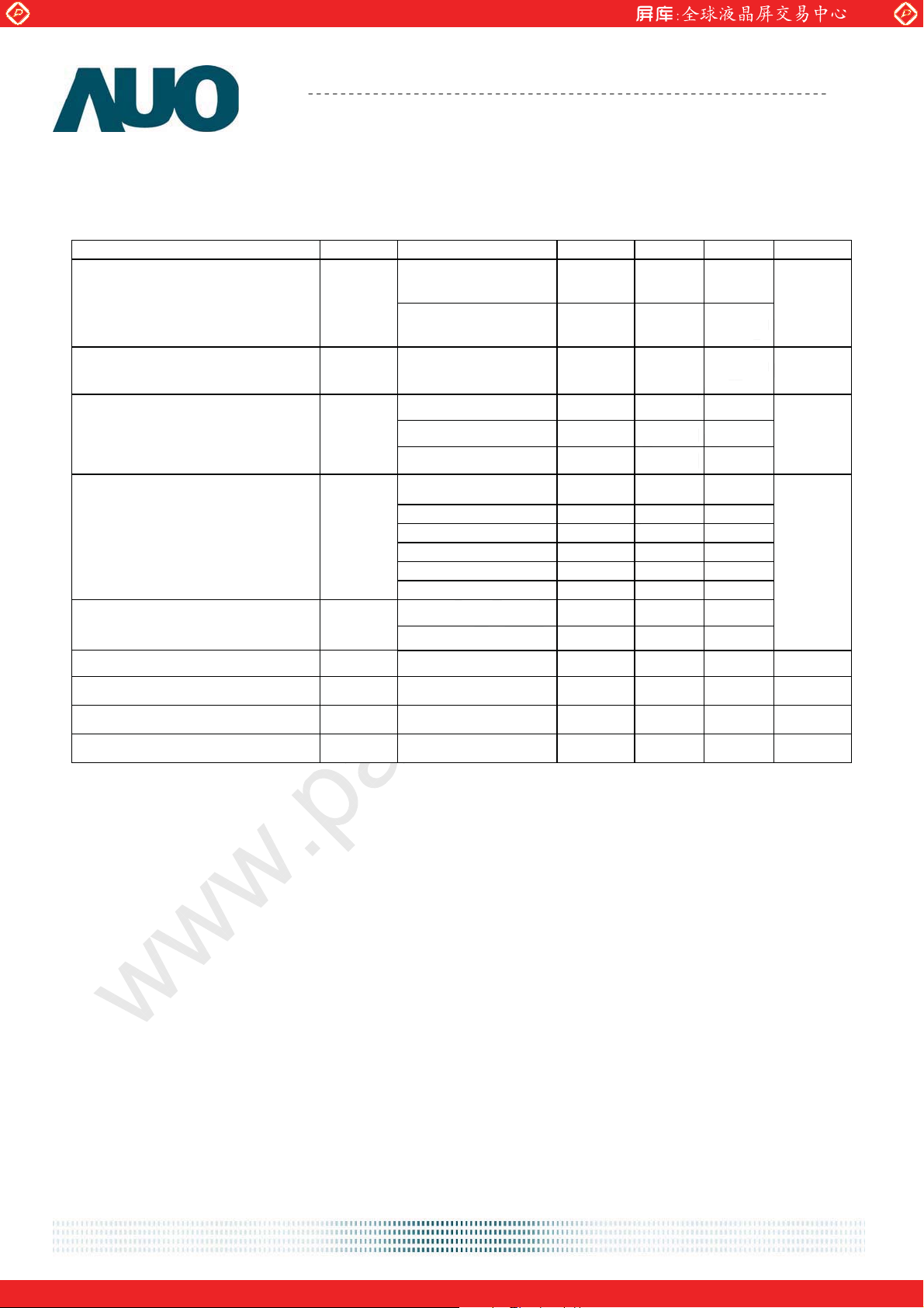
2.2 Optical Characteristics
The optical characteristics are measured under stable conditions at 25к:
Item Unit Conditions Min. Typ. Max. Note
Viewing Angle [degree]
Contrast ratio Normal Direction
Response Time [msec]
Color / Chromaticity
Coordinates (CIE)
Color Coordinates (CIE) White
Horizontal (Right)
CR = 10 (Left)
Vertical (Up)
CR = 10 (Down)
Raising Time (TrR)
Falling Time (TrF)
Raising + Falling
Red x 0.610 0.640 0.670
Red y 0.301 0.331 0.361
Green x 0.304 0.334 0.364
Green y 0.592 0.622 0.652
Blue x 0.126 0.156 0.186
Blue y 0.019 0.049 0.079
White x 0.280 0.310 0.340
White y 0.296 0.326 0.356
40
40
15
40
420
-
-
-
M185XTN01.0
45
45
20
45
700 -
3.6 5.7
1.4 2.3
5 8
-
-
-
-
2
3
4
5
Central Luminance [cd/m2] 160 200 - 6
Luminance Uniformity
Crosstalk (in 60Hz)
Flicker
[%]
[%]
dB
75 80
-
1.5 8
-20
document version 1.0 6
7
9
One step solution for LCD / PDP / OLED panel application: Datasheet, inventory and accessory!
www.panelook.com
Page 7
Global LCD Panel Exchange Center
www.panelook.com
Product Specification
AU OPTRONICS CORPORATION
M185XTN01.0
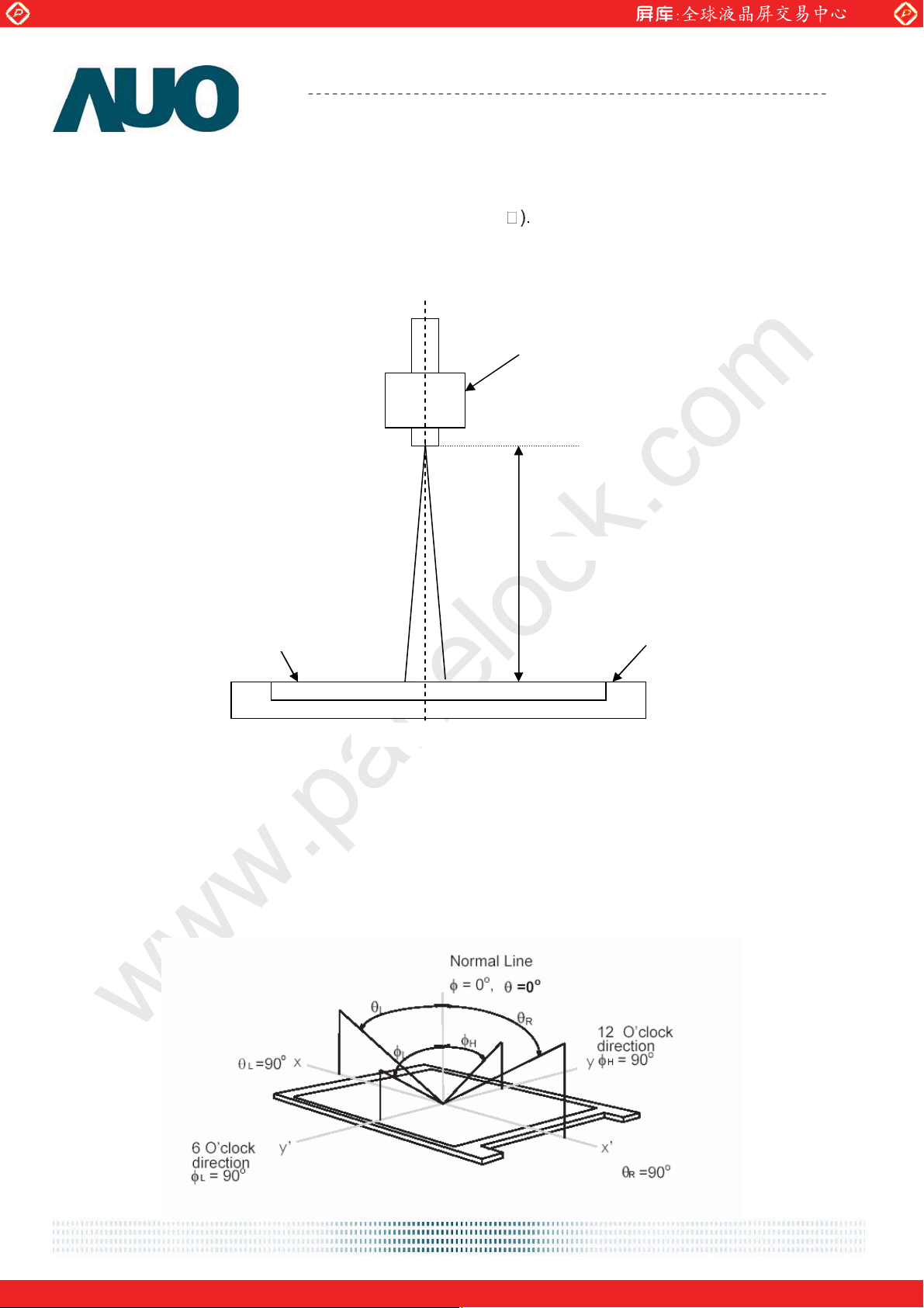
Note 1: Measurement method
The LCD module should be stabilized at given temperature for 30 minutes to avoid abrupt
temperature change during measuring (at surface 35
. In order to stabilize the luminance, the
measurement should be executed after lighting Backlight for 30 minutes in a stable, windless and
dark room. ʳ
Photo detector
Measured distance
LCD Panel
Center of the screen
Note 2: Definition of viewing angle measured by ELDIM (EZContrast 88)
Viewing angle is the measurement of contrast ratio Њ10, at the screen center, over a 180°
horizontal and 180° vertical range (off-normal viewing angles). The 180° viewing angle range is
broken down as follows; 90° (θ) horizontal left and right and 90° (Φ) vertical, high (up) and low
(down). The measurement direction is typically perpendicular to the display surface with the
screen rotated about its center to develop the desired measurement viewing angle.
TFT-LCD Module
document version 1.0 7
One step solution for LCD / PDP / OLED panel application: Datasheet, inventory and accessory!
www.panelook.com
Page 8
Global LCD Panel Exchange Center
www.panelook.com
Product Specification
AU OPTRONICS CORPORATION
M185XTN01.0
Note 3: Contrast ratio is measured by TOPCON SR-3
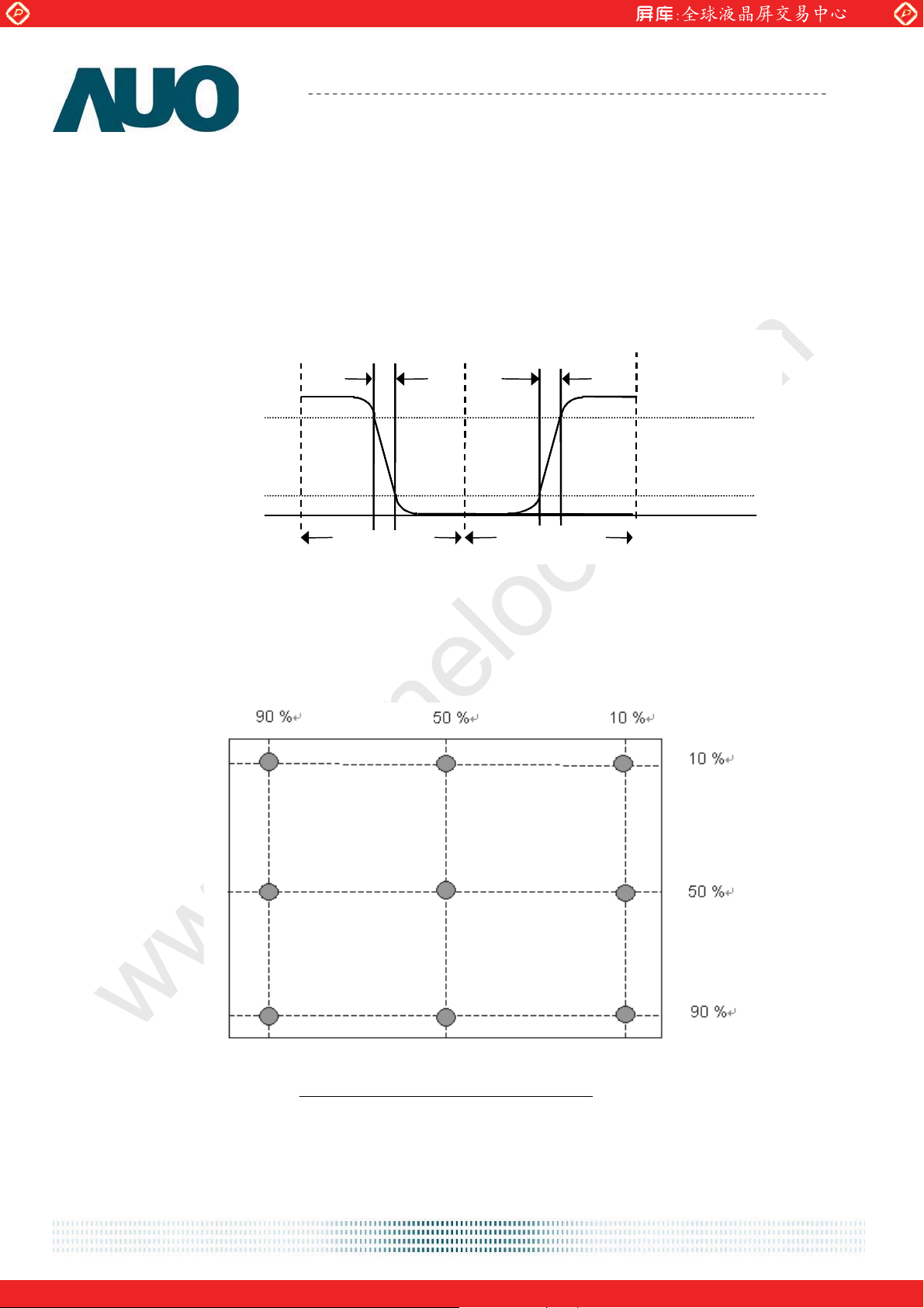
Note 4: Definition of Response time measured by Westar TRD-100A
The output signals of photo detector are measured when the input signals are changed from “Full
Black” to “Full White” (rising time, Tr
), and from “Full White” to “Full Black” (falling time, TfF),
R
respectively. The response time is interval between the 10% and 90% (1 frame at 60 Hz) of
amplitudes.
Optical
Optical
response
response
100
100
90
10
10
%
%
White Black
0
0
Tr
Tr
F
F
Black
1 Frame 1 Frame
Tr
Tr
R
R
White
+ TfF = 5 msec (typ.).
Tr
R
Note 5: Color chromaticity and coordinates (CIE) is measured by TOPCON SR-3
Note 6: Central luminance is measured by TOPCON SR-3
Note 7: Luminance uniformity of these 9 points is defined as below and measured by
TOPCON SR-3
Uniformity =
9)-(1 points 9in LuminanceMinimum
9)-(1 Points 9in LuminanceMaximum
document version 1.0 8
One step solution for LCD / PDP / OLED panel application: Datasheet, inventory and accessory!
www.panelook.com
Page 9
Global LCD Panel Exchange Center
L
www.panelook.com
Product Specification
AU OPTRONICS CORPORATION
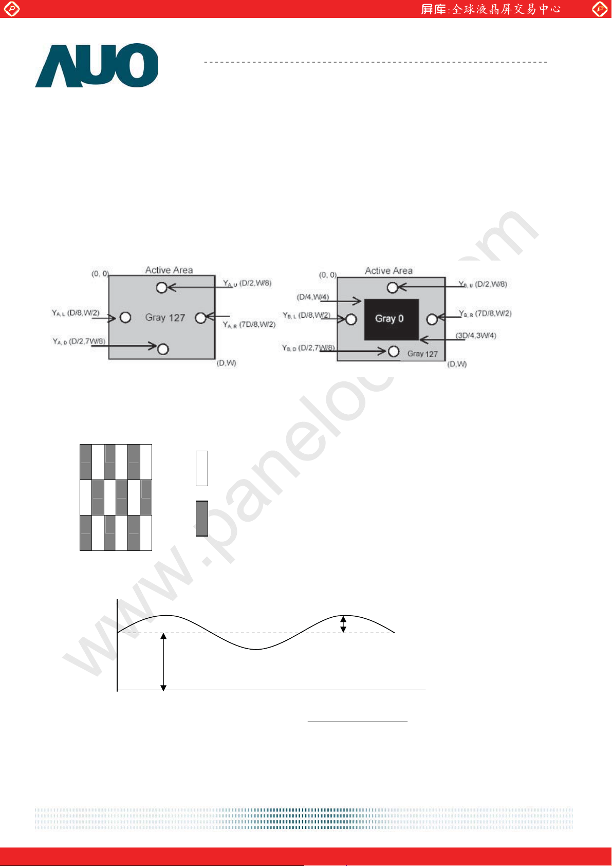
Note 8: Crosstalk is defined as below and measured by TOPCON SR-3
CT = | YB – YA | / YA Ø 100 (%)
Where
YA = Luminance of measured location without gray level 0 pattern (cd/m2)
YB = Luminance of measured location with gray level 0 pattern (cd/m2)
M185XTN01.0
Note 9: Test Patern: Subchecker Pattern measured by TOPCON SR-3
RGBRGB
Gray Level = L127
R GBRGB
RGBRGB
Gray Level = L0
Method: Record dBV & DC value with TRD-100
Amplitude
DC
AC
Time
Hz) 30Level(at AC
log20(dB)Flicker =
evel DC
document version 1.0 9
One step solution for LCD / PDP / OLED panel application: Datasheet, inventory and accessory!
www.panelook.com
Page 10
Global LCD Panel Exchange Center
www.panelook.com
Product Specification
AU OPTRONICS CORPORATION
M185XTN01.0
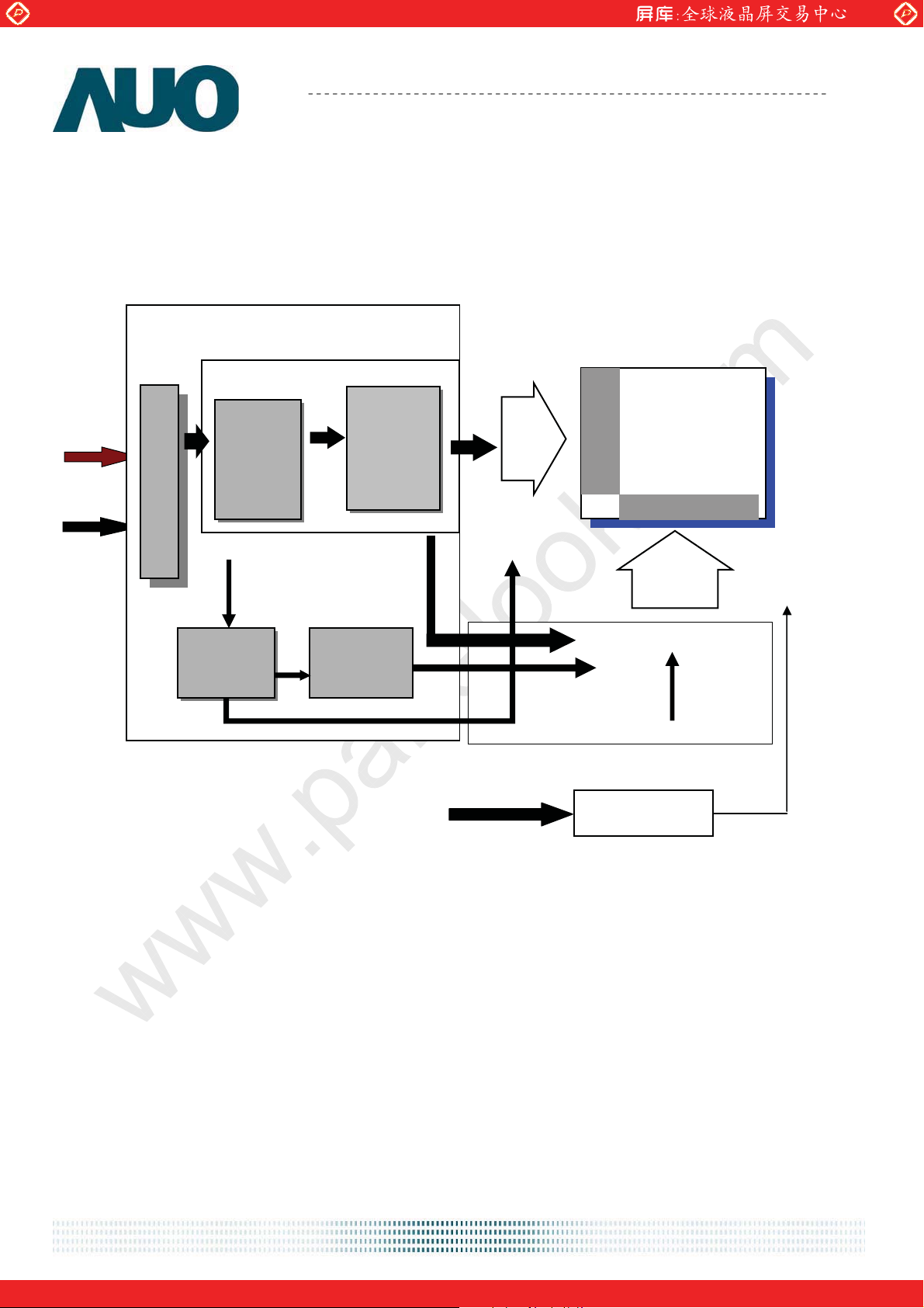
3.0 Functional Block Diagram
The following diagram shows the functional block of the 18.5 inch Color TFT-LCD Module:
LVDS
+5V
LVDS
Receiver
Connector
AUO
ASIC
Timing
Controller
mini
Transmitter
G1
G768
Y-Driver IC
TFT-LCD
1366(x3) x 768
Pixels
-
D1 D4098
LED
DC/DC
Converter
I/F + X-PCB
Gamma
Correction
DC
Driver
I/F PCB Interface:
093F30-00T01A-M4(STARCONN) /01-187121-30091-3(A) (P-TWO)
Mating Type:
FI-X30HL(JAE) (Locked Type)
FI-X30H (JAE)(Unlocked Type)
document version 1.0 10
One step solution for LCD / PDP / OLED panel application: Datasheet, inventory and accessory!
www.panelook.com
Page 11
Global LCD Panel Exchange Center
www.panelook.com
Product Specification
AU OPTRONICS CORPORATION
M185XTN01.0
4.0 Absolute Maximum Ratings
Absolute maximum ratings of the module are as following:
4.1 TFT LCD Module
Item Symbol Min Max Unit Conditions
Logic/LCD Drive
Voltage
VDD 0 +5.5 [Volt] Note 1,2
4.2 Backlight Unit
Item Symbol Min Max Unit Conditions
LED Current ILED
- 63
[mA] Note 1,2
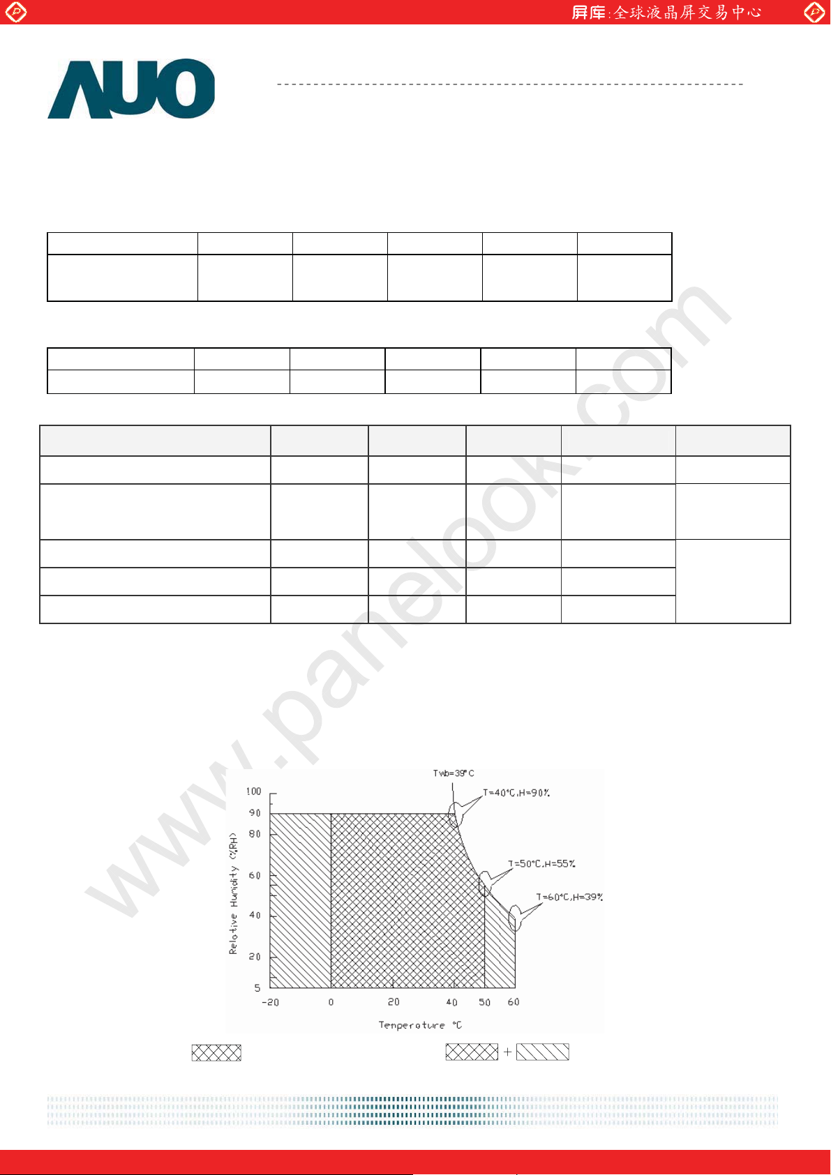
4.3 Absolute Ratings of Environment
Item Symbol Min. Max. Unit Conditions
Operating Temperature TOP 0 +50 [oC] Note 3
Glass surface temperature
(operation)
Operation Humidity HOP 5 90 [%RH]
Storage Temperature TST -20 +60 [oC]
Storage Humidity HST
Note 1: With in Ta (25к)
Note 2: Permanent damage to the device may occur if exceeding maximum values
Note 3: Temperature and relative humidity range are shown as the below figure.
1. 90% RH Max ( Taʳ Љˆˌкʼʳ
2. Max wet-bulb temperature at 39кʳ ʳ˿˸ˁʳʻʳ˧˴ʳ Љˆˌкʼʳ
ʳʳʳʳʳʳʳʳˆˁʳˡʳ˶˷˸˴˼ʳ
Note 4: Function Judged only
TGS 0 +65 [
5 90
o
C] Note 3, Note 4
[%RH]
Note 3
Operating Range
document version 1.0 11
Storage Range
One step solution for LCD / PDP / OLED panel application: Datasheet, inventory and accessory!
www.panelook.com
Page 12
Global LCD Panel Exchange Center
www.panelook.com
Product Specification
M185XTN01.0
AU OPTRONICS CORPORATION
5.0 Electrical characteristics
5.1 TFT LCD Module
5.1.1 Power Specification
Input power specifications are as following:
Symbol Parameter Min Typ Max Unit Conditions
VDD
Logic/LCD Drive
Voltage
IDD Input Current
PDD
VDD Power
4.5
5.0
-
0.35
- 0.42 0.5
-
1.75 2.1
- 2.1 2.5
5.5
0.42
[Volt] +/-10%
VDD= 5.0V, All Black Pattern
At 60Hz,
[A]
VDD= 5.0V, All Black Pattern
At 75Hz
VDD= 5.0V, All Black Pattern
At 60Hz
[Watt]
VDD= 5.0V, All Black Pattern
At 75Hz
IRush Inrush Current
VDDrp
Allowable Logic/LCD
Drive Ripple Voltage
-
-
- 2
- 350
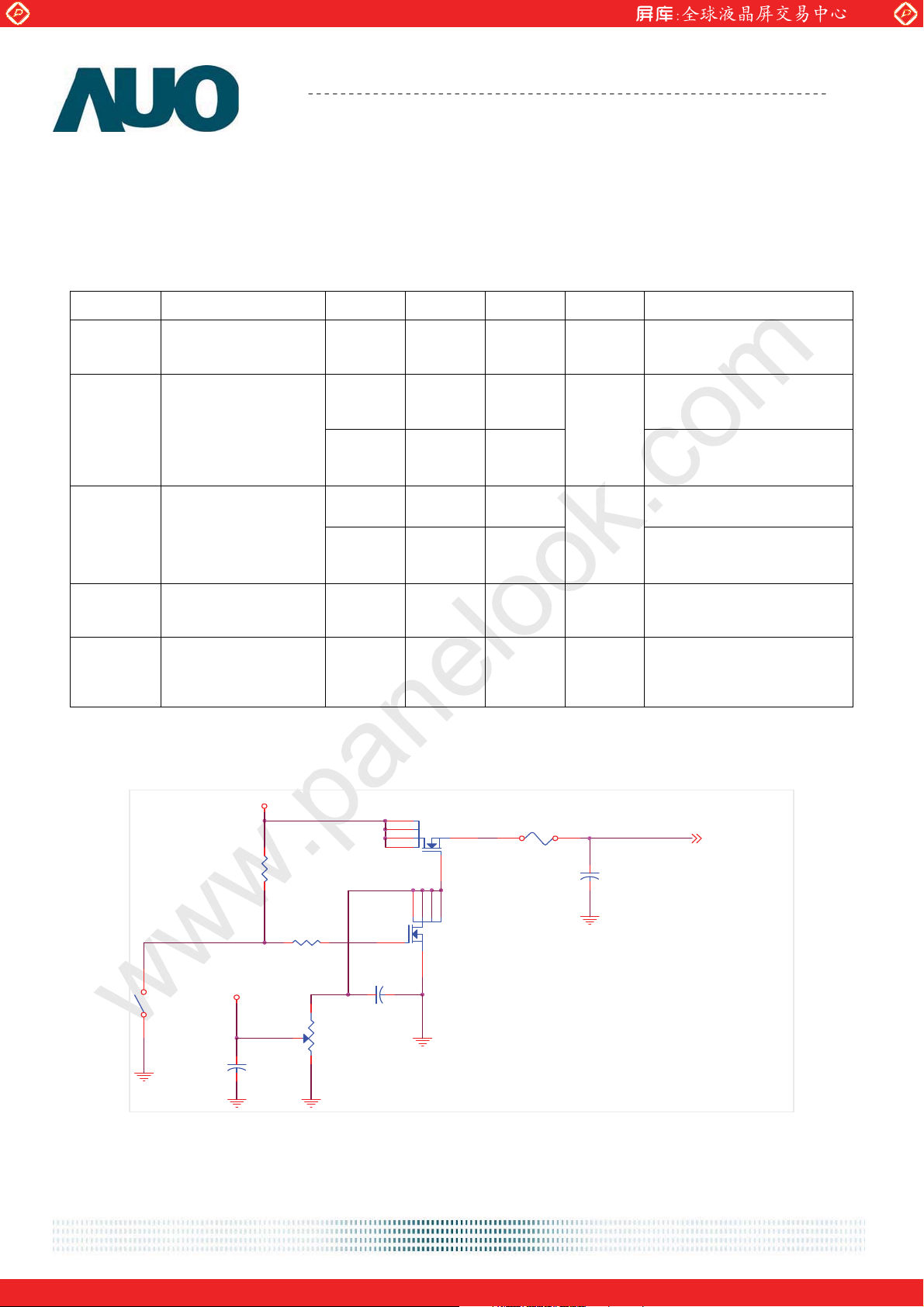
Note 1: Measurement conditions:
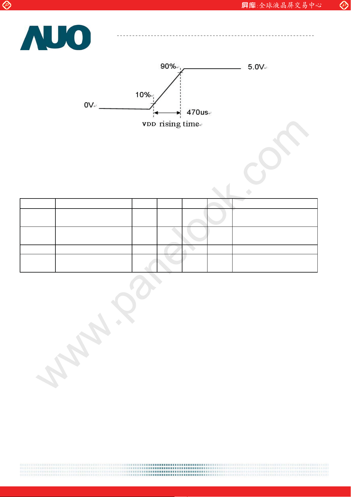
The duration of rising time of power input is 470us.
(High to Low)
Control
Signal
SW1
SW MAG-SPST
1 2
+12.0V
+5.0V
R1
47K
R2
1K
VR1
47K
D6
D5
D2 S
D1
G
C3
0.01uF/25V
Q3
AO6402
D2SD1D5
G
D6
Q3
AO6402
[A] Note 1
[mV] p-p
F1
VDD= 5.0V, All Black Pattern
At 75Hz
VCC
C1
1uF/16V
(LCD Module Input)
C2
1uF/25V
document version 1.0 12
One step solution for LCD / PDP / OLED panel application: Datasheet, inventory and accessory!
www.panelook.com
Page 13
Global LCD Panel Exchange Center
www.panelook.com
Product Specification
M185XTN01.0
AU OPTRONICS CORPORATION
5.1.2 Signal Electrical Characteristics
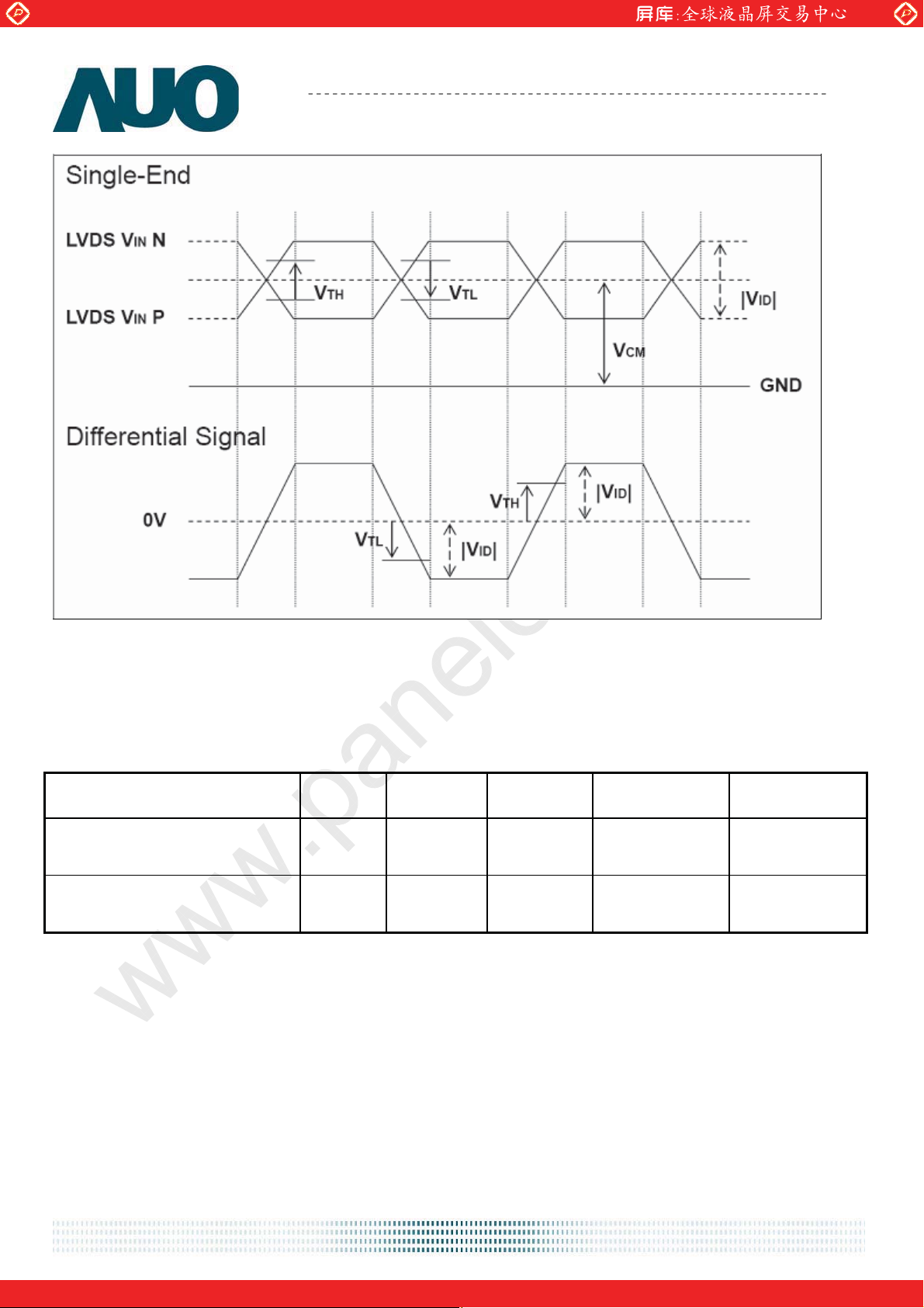
Input signals shall be low or Hi-Z state when VDD is off. Please refer to specifications of
SN75LVDS82DGG (Texas Instruments) in detail.
1. DC Characteristics of each signal are as following:
Symbol Parameter Min Typ Max Units Condition
VTH
VTL
Differential Input High
Threshold
Differential Input Low
Threshold
- - +100 [mV]
-100 - - [mV]
VICM = 1.2V
Note 1
VICM = 1.2V
Note 1
ūVIDū Input Differential Voltage 100 - 600 [mV] Note 1
VICM
Differential Input Common
Mode Voltage
+1.0 +1.2 +1.5 [V]
VTH-VTL = 200MV (max)
Note 1
Note 1: LVDS Signal Waveform
document version 1.0 13
One step solution for LCD / PDP / OLED panel application: Datasheet, inventory and accessory!
www.panelook.com
Page 14
Global LCD Panel Exchange Center
www.panelook.com
Product Specification
M185XTN01.0
AU OPTRONICS CORPORATION
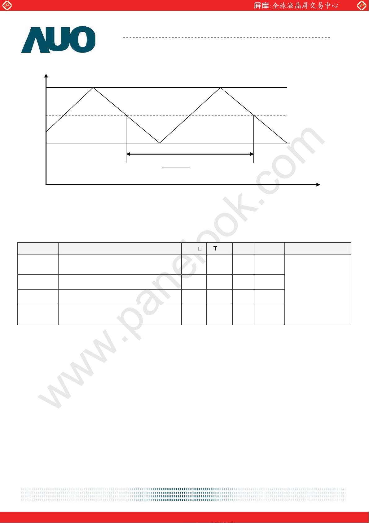
2. AC Characteristics
Description Symbol Min Max Unit Note
Maximum deviation of input
clock frequency during SSC
Maximum modulation frequency
of input clock during SSC
FDEV -
3
%
FMOD - 200 KHz
document version 1.0 14
One step solution for LCD / PDP / OLED panel application: Datasheet, inventory and accessory!
www.panelook.com
Page 15
Global LCD Panel Exchange Center
q
x
r
V
t
www.panelook.com
Fre
Fma
Fcente
Fmin
Product Specification
M185XTN01.0
AU OPTRONICS CORPORATION
Fcenter * FDE
1
F
MOD
< Spread Spectrum>
ime
5.2 Backlight Unit
Parameter guideline for LED driving is under stable conditions at 25к (Room Temperature):
Symbol Parameter Min.
IR
LED Operation Current 57 60 63
LED
VLB
P
BLU Power consumption (for reference)
BLU
LT
LED life Time
LED
Light Bar Operation Voltage
(for reference)
Note 1 :The specified current is input LED chip 100% duty current.
Note 2 : The value showed in the table is one light bar’s operation voltage.
Note 3 : Definition of life time : brightness becomes 50% of its original value. The minimum life time of LED unit is on
the condition of IR
= 60mA and 25±2к(Room temperature).
LED
Note 4: Each LED light bar consists of 40 pcs LED package ( 4 strings x 10 pcs / string ).
Typ. Max. Unit Note
[mA]
Note 1
21 23.8 25.2
[Volt]
Note 2
4.8 5.7 6.4 [Watt]
30000 - -
[Hour]
Note 3
Operating with fixed
driving current
document version 1.0 15
One step solution for LCD / PDP / OLED panel application: Datasheet, inventory and accessory!
www.panelook.com
Page 16
Global LCD Panel Exchange Center
www.panelook.com
Product Specification
AU OPTRONICS CORPORATION
6.0 Signal Characteristic
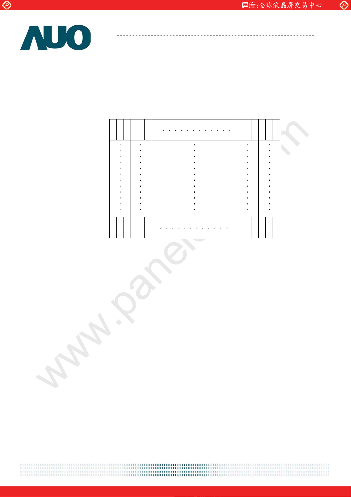
6.1 Pixel Format Image
Following figure shows the relationship of the input signals and LCD pixel format.
1st Line
1 2 1365 1366
R G B R G B
R G B R G B
M185XTN01.0
768 Line
R G B R G B
R G B R G B
document version 1.0 16
One step solution for LCD / PDP / OLED panel application: Datasheet, inventory and accessory!
www.panelook.com
Page 17
Global LCD Panel Exchange Center
www.panelook.com
Product Specification
AU OPTRONICS CORPORATION
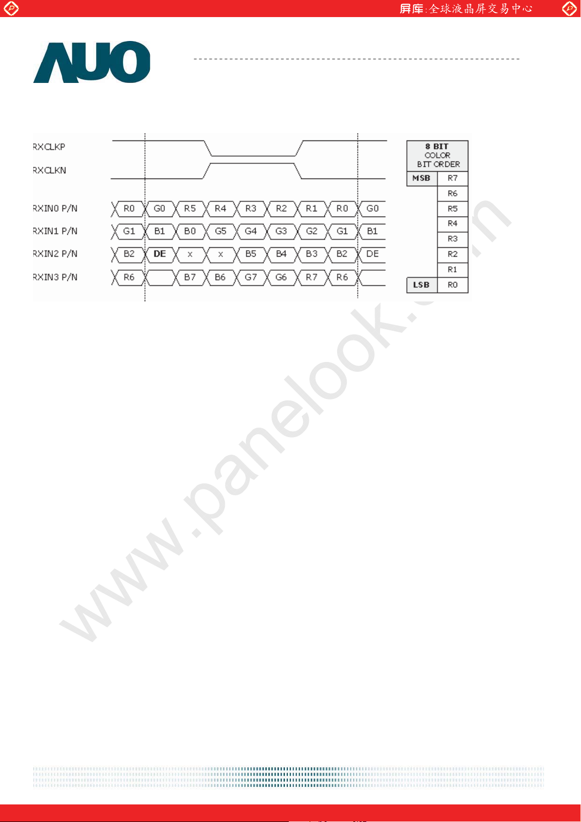
6.2 The input data format
Note1: Normally, DE, VS, HS on EVEN channel are not used.
Note2: 8-bits signal input.
LVDS Data Mapping of NS Format
M185XTN01.0
document version 1.0 17
One step solution for LCD / PDP / OLED panel application: Datasheet, inventory and accessory!
www.panelook.com
Page 18
Global LCD Panel Exchange Center
www.panelook.com
Product Specification
AU OPTRONICS CORPORATION
M185XTN01.0
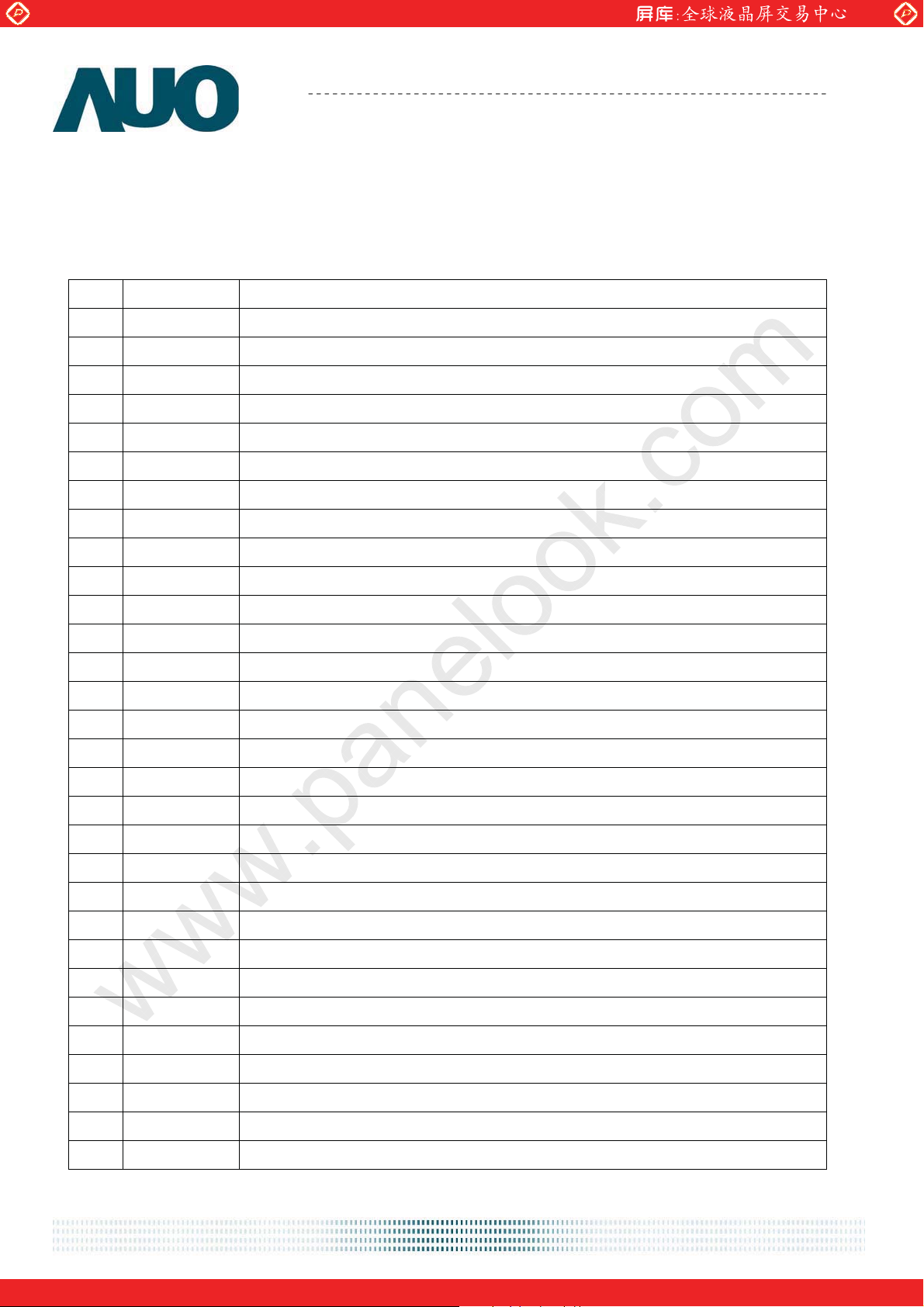
6.3 Signal Description
The module using one LVDS receiver SN75LVDS82(Texas Instruments). LVDS is a
differential signal technology for LCD interface and high speed data transfer device. LVDS
transmitters shall be SN75LVDS83(negative edge sampling). The first LVDS port(RxOxxx)
transmits odd pixels while the second LVDS port(RxExxx) transmits even pixels.
PIN # SIGNAL NAME DESCRIPTION
1 NC No contact (For AUO internal use)
2 NC No contact (For AUO internal use)
3 NC No contact (For AUO internal use)
4 GND Power Ground
5 RXIN0- Negative LVDS differential data input (0)
6 RXIN0+ Positive LVDS differential data input (0)
7 GND Power Ground
8 RXIN1- Negative LVDS differential data input (1)
9 RXIN1+ Positive LVDS differential data input (1)
10 GND Power Ground
11 RXIN2- Negative LVDS differential data input (2)
12 RXIN2+ Positive LVDS differential data input (2)
13 GND Power Ground
14 RXCLKIN- Negative LVDS differential clock input (clock)
15 RXCLKIN+ Positive LVDS differential data input (clock)
16 GND Power Ground
17 RXIN3- Negative LVDS differential data input (3)
18 RXIN3+ Positive LVDS differential data input (3)
19 GND Power Ground
20 NC No contact (For AUO internal use)
21 NC No contact (For AUO internal use)
22 NC No contact (For AUO internal use)
23 GND Power Ground
24 GND Power Ground
25 GND Power Ground
26 VCC +5V power supply
27 VCC +5V power supply
28 VCC +5V power supply
29 VCC +5V power supply
30 VCC +5V power supply
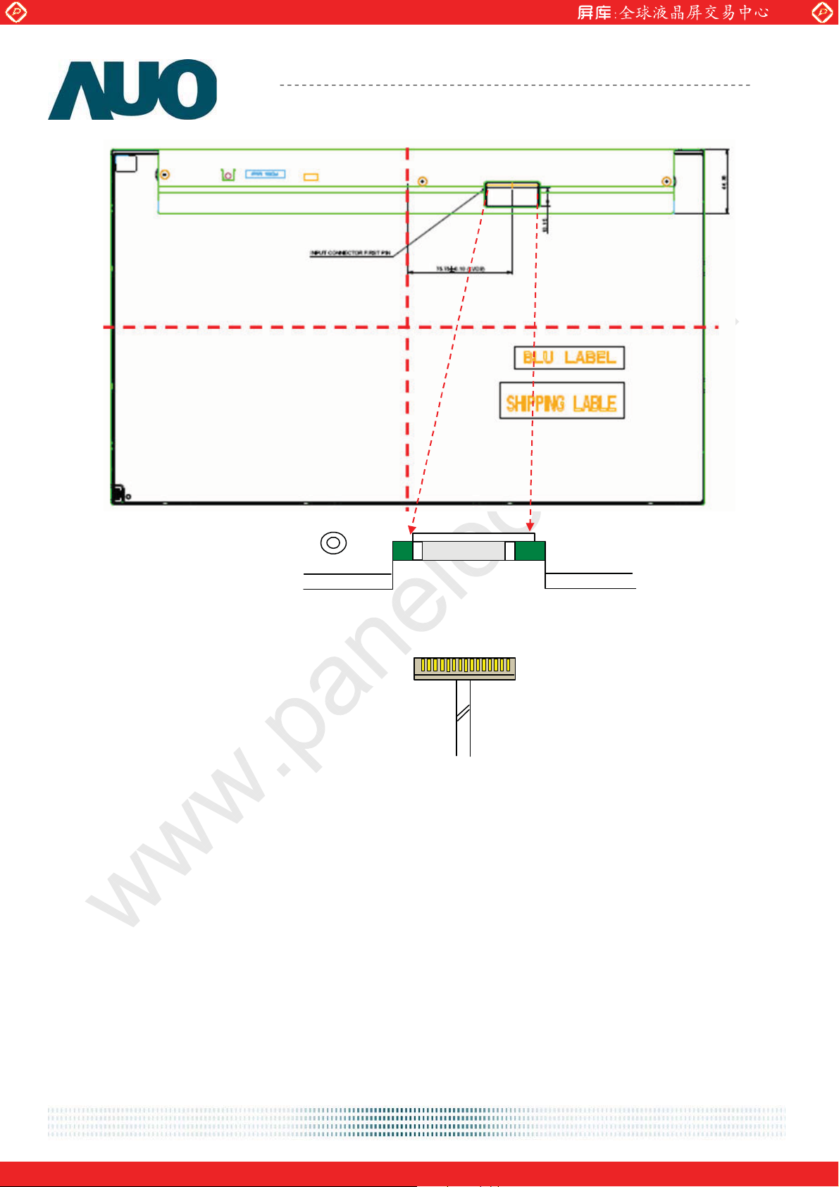
Note1: Start from left side
document version 1.0 18
One step solution for LCD / PDP / OLED panel application: Datasheet, inventory and accessory!
www.panelook.com
Page 19
Global LCD Panel Exchange Center
www.panelook.com
Product Specification
AU OPTRONICS CORPORATION
M185XTN01.0
1
NC
Note2: Input signals of clock shall be the same timing.
Note3: Please follow TV VESA Pin Assignment.
30
VCC
document version 1.0 19
One step solution for LCD / PDP / OLED panel application: Datasheet, inventory and accessory!
www.panelook.com
Page 20
Global LCD Panel Exchange Center
www.panelook.com
Product Specification
AU OPTRONICS CORPORATION
M185XTN01.0
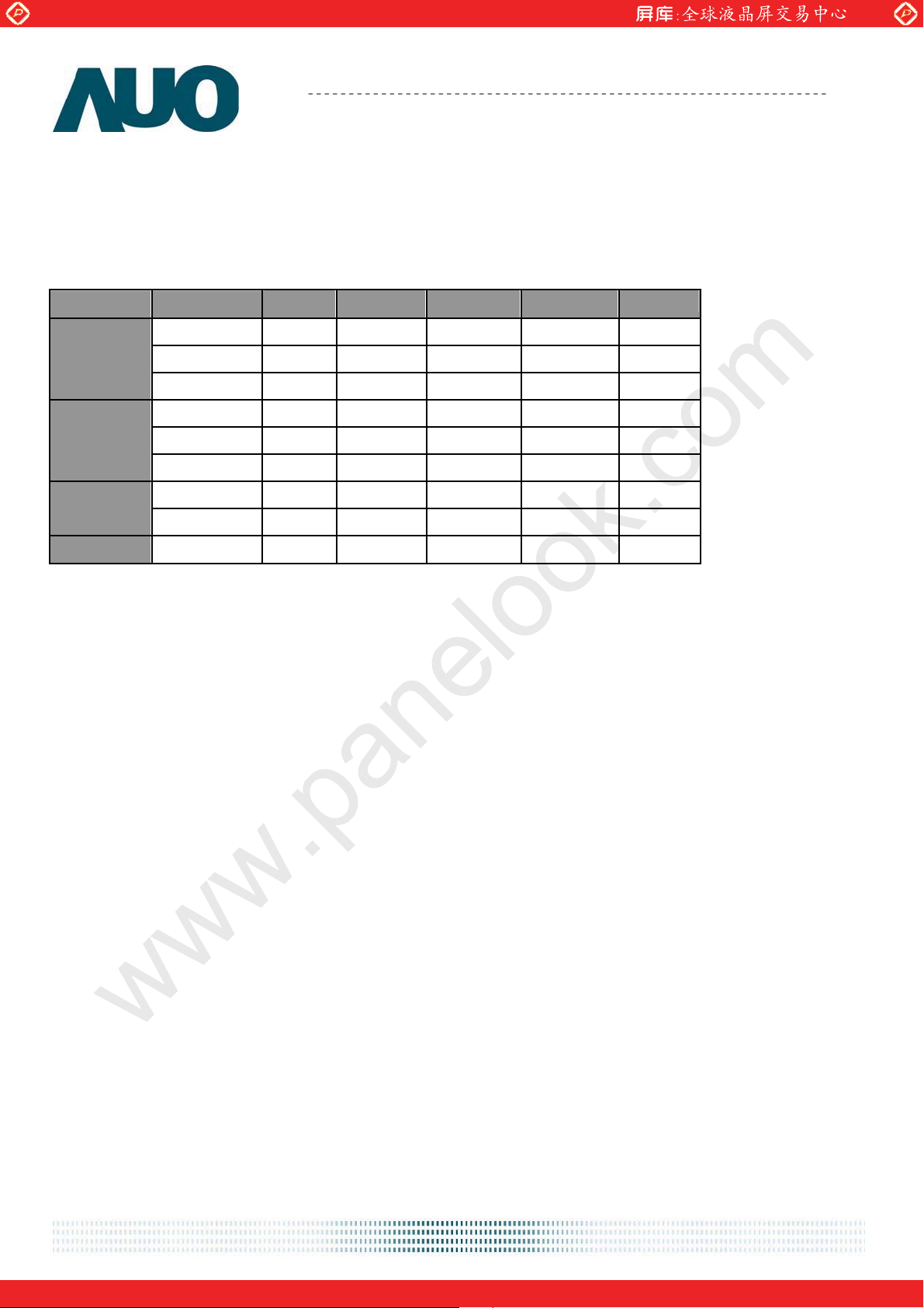
6.4 Timing Characteristics
Basically, interface timing described here is not actual input timing of LCD module but close to
output timing of SN75LVDS82DGG (Texas Instruments) or equivalent.
˦˼˺˴˿
˦˼˺˴˿ʳʳʳʳ
˦˼˺˴˿˦˼˺˴˿
Item
Symbol Min Typ Max Unit
Period Tv 776 808 1023 Th
V-section
H-section
Active Tdisp(v) 768 768 768
Blanking Tblk(v) 8 40 255
Period Th 1416ʳ 1606 2047
Active Tdisp(h) 1366 1366 1366
Blanking Tblk(h) 50ʳ 240 681
Th
Th
Tclk
Tclk
Tclk
Period Tclk - 12.8 - ns
˖˿˶˾
˖˿˶˾ʳʳʳʳ
˖˿˶˾˖˿˶˾
˙˴˸ʳ˥˴˸
˙˴˸ʳ˥˴˸ʳʳʳʳ
˙˴˸ʳ˥˴˸˙˴˸ʳ˥˴˸
Frequency
Frame Rate
Freq
F
55 78 90 MHz
50 60 75 Hz
Note1 : DE mode only
Note2 : Clock Frequency 90MHz(Max.)= 1416(H)*847(V)*75Hz
document version 1.0 20
One step solution for LCD / PDP / OLED panel application: Datasheet, inventory and accessory!
www.panelook.com
Page 21
Global LCD Panel Exchange Center
www.panelook.com
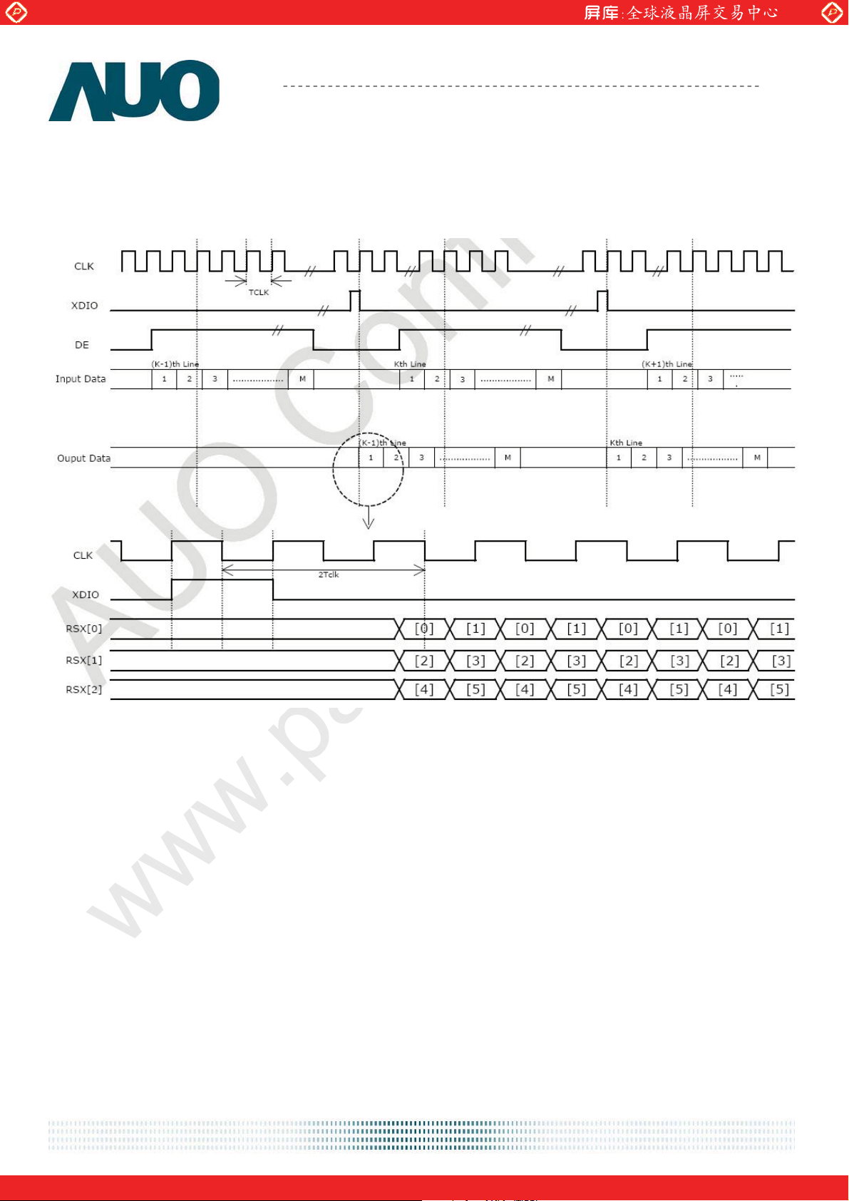
6.5 Timing diagram
Product Specification
M185XTN01.0
AU OPTRONICS CORPORATION
document version 1.0 21
One step solution for LCD / PDP / OLED panel application: Datasheet, inventory and accessory!
www.panelook.com
Page 22
Global LCD Panel Exchange Center
www.panelook.com
Product Specification
AU OPTRONICS CORPORATION
M185XTN01.0
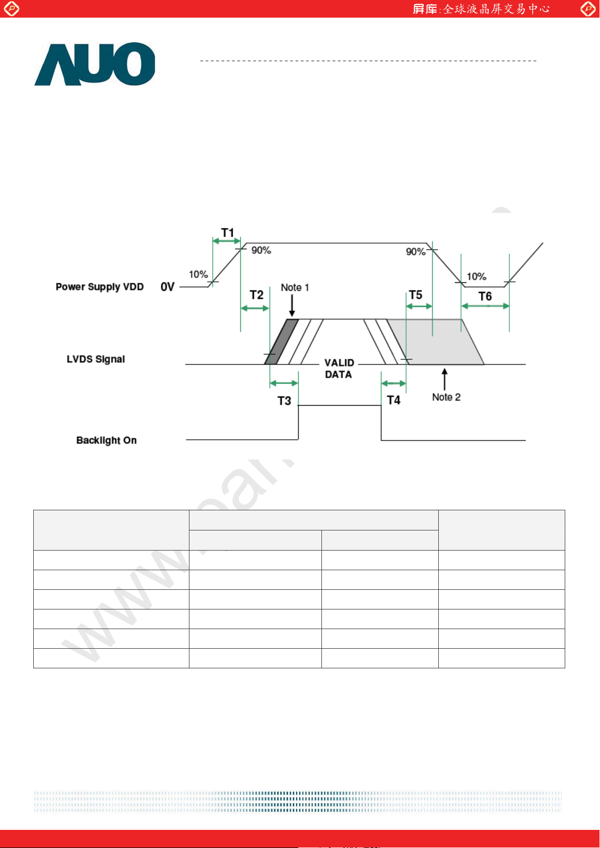
6.6 Power ON/OFF Sequence
VDD power and lamp on/off sequence are as follows. Interface signals are also shown in the
chart. Signals from any system shall be Hi-Z state or low level when VDD is off.
Note 1: Insert a black pattern
Note 2: Insert a white pattern after valid data and last until VDD falls to 10%
Value
Parameter
Min. Max.
T1 0.5 10 [msec]
T2 0 50 [msec]
T3 500 - [msec]
T4 200 - [msec]
T5 40 - [msec]
T6 1000 - [msec]
Unit
document version 1.0 22
One step solution for LCD / PDP / OLED panel application: Datasheet, inventory and accessory!
www.panelook.com
Page 23
Global LCD Panel Exchange Center
www.panelook.com
Product Specification
AU OPTRONICS CORPORATION
M185XTN01.0
7.0 Connector & Pin Assignment
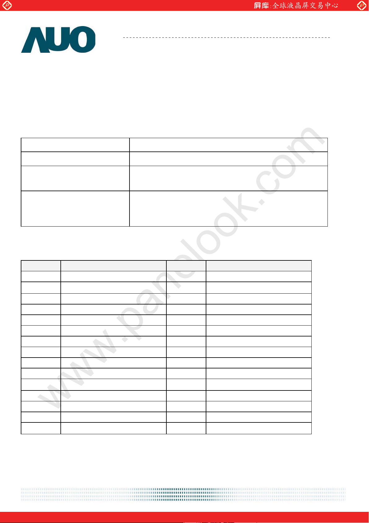
Physical interface is described as for the connector on module. These connectors are capable of
accommodating the following signals and will be following components.
7.1 TFT LCD Module
Connector Name / Designation Interface Connector / Interface card
Manufacturer STARCONN or P-TWO
093F30-00T01A-M4(STARCONN)
Type Part Number
Mating Housing Part Number
/01-187121-30091-3(A) (P-TWO)
FI-X30HL(JAE) (Locked Type)
FI-X30H (JAE)(Unlocked Type)
7.1.1 LVDS Connector Pin Assignment
Pin# Signal Name Pin# Signal Name
1 NC 2 NC
3 NC 4 GND
5 RXIN0- 6 RXIN0+
7 GND 8 RXIN1-
9 RXIN1+ 10 GND
11 RXIN2- 12 RXIN2+
13 GND 14 RXCLKIN-
15 RXCLKIN+ 16 GND
17 RXIN3- 18 RXIN3+
19 GND 20 NC
21 NC 22 NC
23 GND 24 GND
25 GND 26 VCC
27 VCC 28 VCC
29 VCC 30 VCC
document version 1.0 23
One step solution for LCD / PDP / OLED panel application: Datasheet, inventory and accessory!
www.panelook.com
Page 24
Global LCD Panel Exchange Center
www.panelook.com
Product Specification
AU OPTRONICS CORPORATION
M185XTN01.0
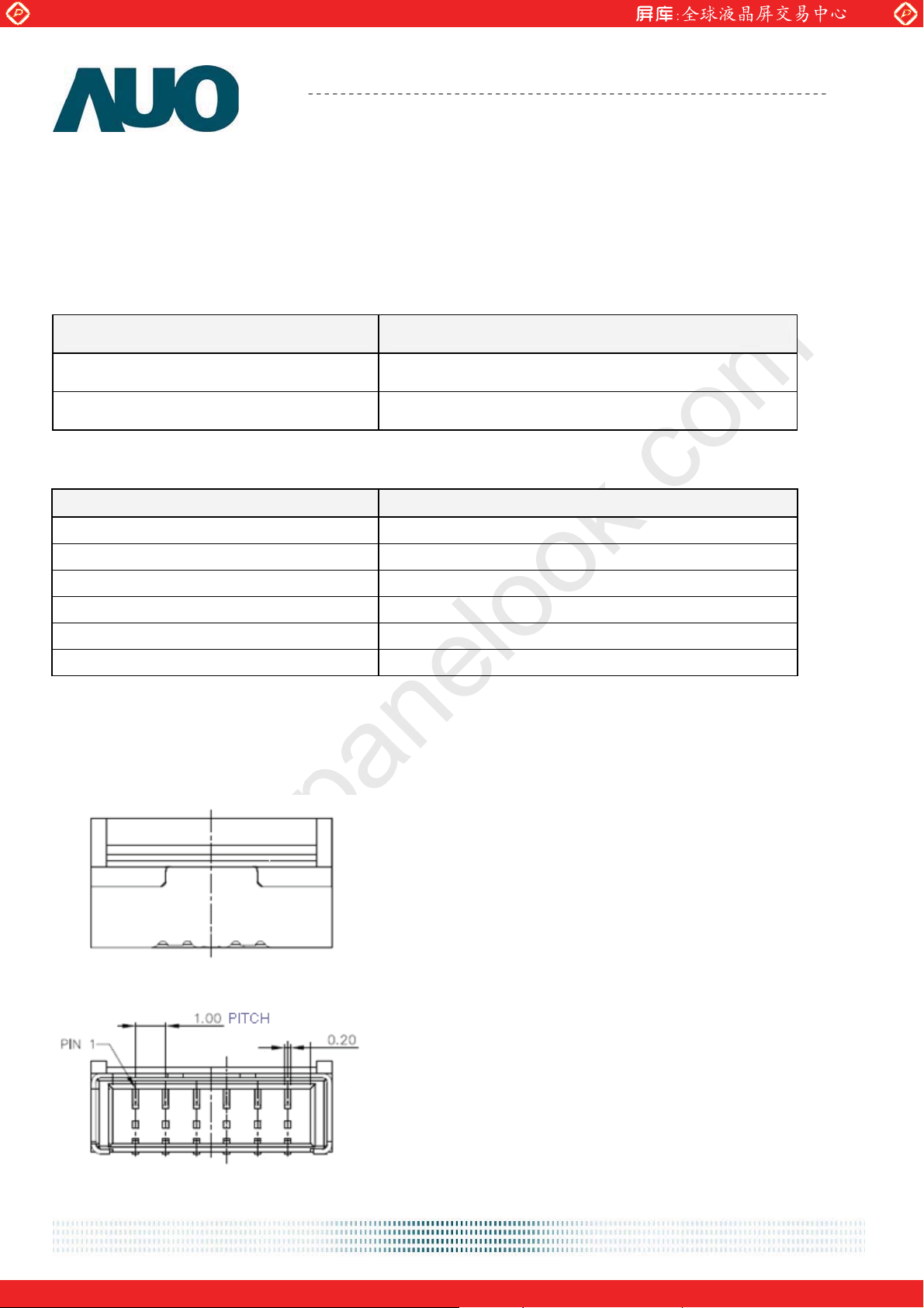
7.2 Recommend connector for Backlight Unit
This connector is mounted on the monitor system board for LED light-bar Wire mating.
Connector Name / Designation Driver Board Connector
Manufacturer
Mating Type Part Number
7.2.1 Light Bar Connector Pin assignment
Pin no. Signal name
1 IRLED (current out)
2 IRLED (current out)
3 VLED (voltage in)
4 VLED (voltage in)
5 IRLED (current out)
6 IRLED (current out)
ENTERY (E&T) Corporationʳ
3707K-S06N-21R
7.2.2 Light Bar Connector Dimension
)(0.1,25.400.39.13 mmunitPitchDVH ==××=××
document version 1.0 24
One step solution for LCD / PDP / OLED panel application: Datasheet, inventory and accessory!
www.panelook.com
Page 25
Global LCD Panel Exchange Center
www.panelook.com
Product Specification
AU OPTRONICS CORPORATION
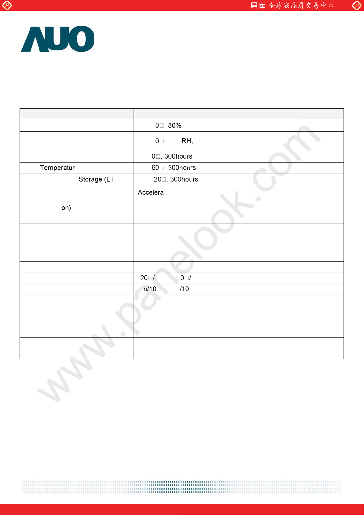
8.0 Reliability Test
Environment test conditions are listed as following table.
Items Required Condition
Temperature Humidity Bias (THB) Ta= 5
High Temperature Operation (HTO) Ta= 5
Low Temperature Operation (LTO) Ta=
High Temperature Storage (HTS) Ta=
Low Temperature Storage (LTS) Ta= -
Vibration Test
(Non-operation)
80%RH, 300hours
50%RH, 300hours
Acceleration: 1.5 Grms
Wave: Random
Frequency: 10 - 200 Hz
Sweep: 30 Minutes each Axis (X, Y, Z)
M185XTN01.0
Note
Acceleration: 50 G
Shock Test
(Non-operation)
Wave: Half-sine
Active Time: 20 ms
Direction: X,ʳY,ʳZ (one time for each Axis)
Drop Test Height: 60 cm, package test
Thermal Shock Test (TST) -
30min, 6
30min, 100 cycles
On/Off Test On/10sec, Off/10sec, 30,000 cycles
1
Contact Discharge: ± 8KV, 150pF(330Ω ) 1sec,
8 points, 25 times/ point.
ESD (Electro Static Discharge)
2
Air Discharge: ± 15KV, 150pF(330Ω ) 1sec
8 points, 25 times/ point.
Altitude Test
Operation:10,000 ft
Non-Operation:30,000 ft
Note 1: The TFT-LCD module will not sustain damage after being subjected to 100 cycles of rapid
temperature change. A cycle of rapid temperature change consists of varying the temperature from
-2˃к to 6˃к, and back again. Power is not applied during the test. After temperature cycling, the
unit is placed in normal room ambient for at least 4 hours before power on.
Note 2: EN61000-4-2, ESD class B: Certain performance degradation allowed
No data lost
Self-recoverable
No hardware failures.
document version 1.0 25
One step solution for LCD / PDP / OLED panel application: Datasheet, inventory and accessory!
www.panelook.com
Page 26
Global LCD Panel Exchange Center
www.panelook.com
Product Specification
AU OPTRONICS CORPORATION
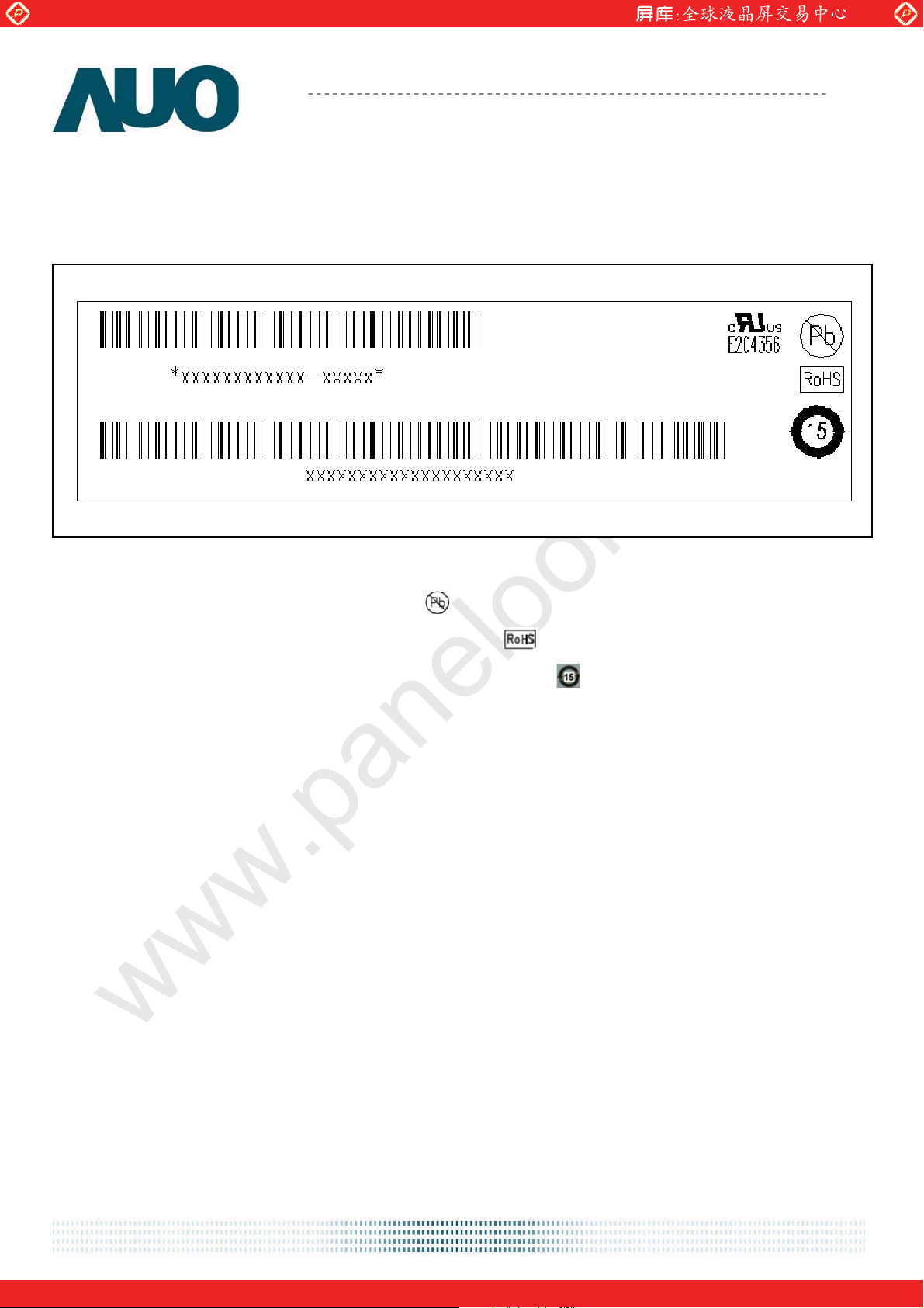
9.0 Shipping Label
The label is on the panel as shown below:
Manufactured: XX/XX
Model No: M185XTN01.0
AU Optronics
Made in XXXXX
M185XTN01.0
Note 1: For Pb Free products, AUO will add
Note 2: For RoHS compatible products, AUO will add
Note 3: For China RoHS compatible products, AUO will add
for identification.
for identification.
for identification.
Note 4: The Green Mark will be presented only when the green documents have been ready by
AUO Internal Green Team.
document version 1.0 26
One step solution for LCD / PDP / OLED panel application: Datasheet, inventory and accessory!
www.panelook.com
Page 27
Global LCD Panel Exchange Center
www.panelook.com
M185XTN01.0
AU OPTRONICS CORPORATION
Product Specification
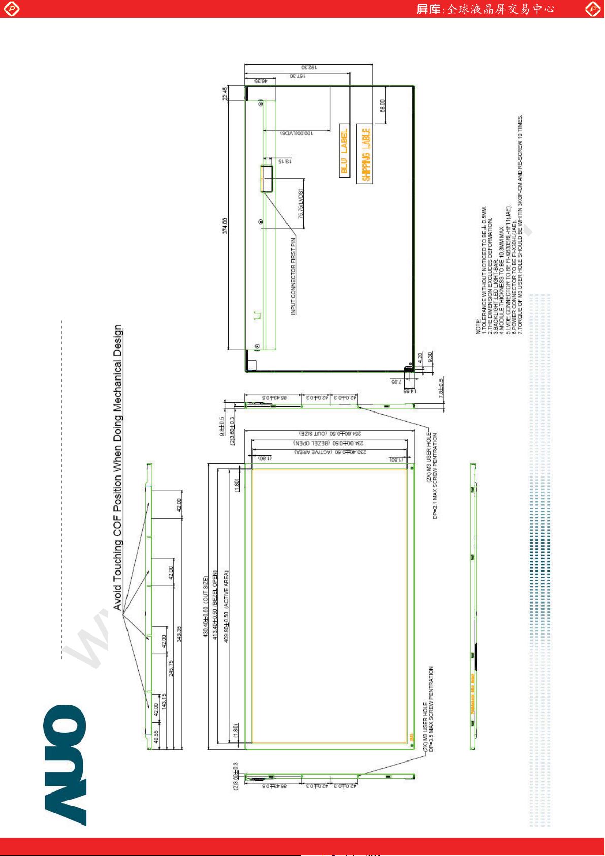
10.0 Mechanical Characteristics
One step solution for LCD / PDP / OLED panel application: Datasheet, inventory and accessory!
document version 0.1
www.panelook.com
Page 28
Global LCD Panel Exchange Center
www.panelook.com
Product Specification
AU OPTRONICS CORPORATION
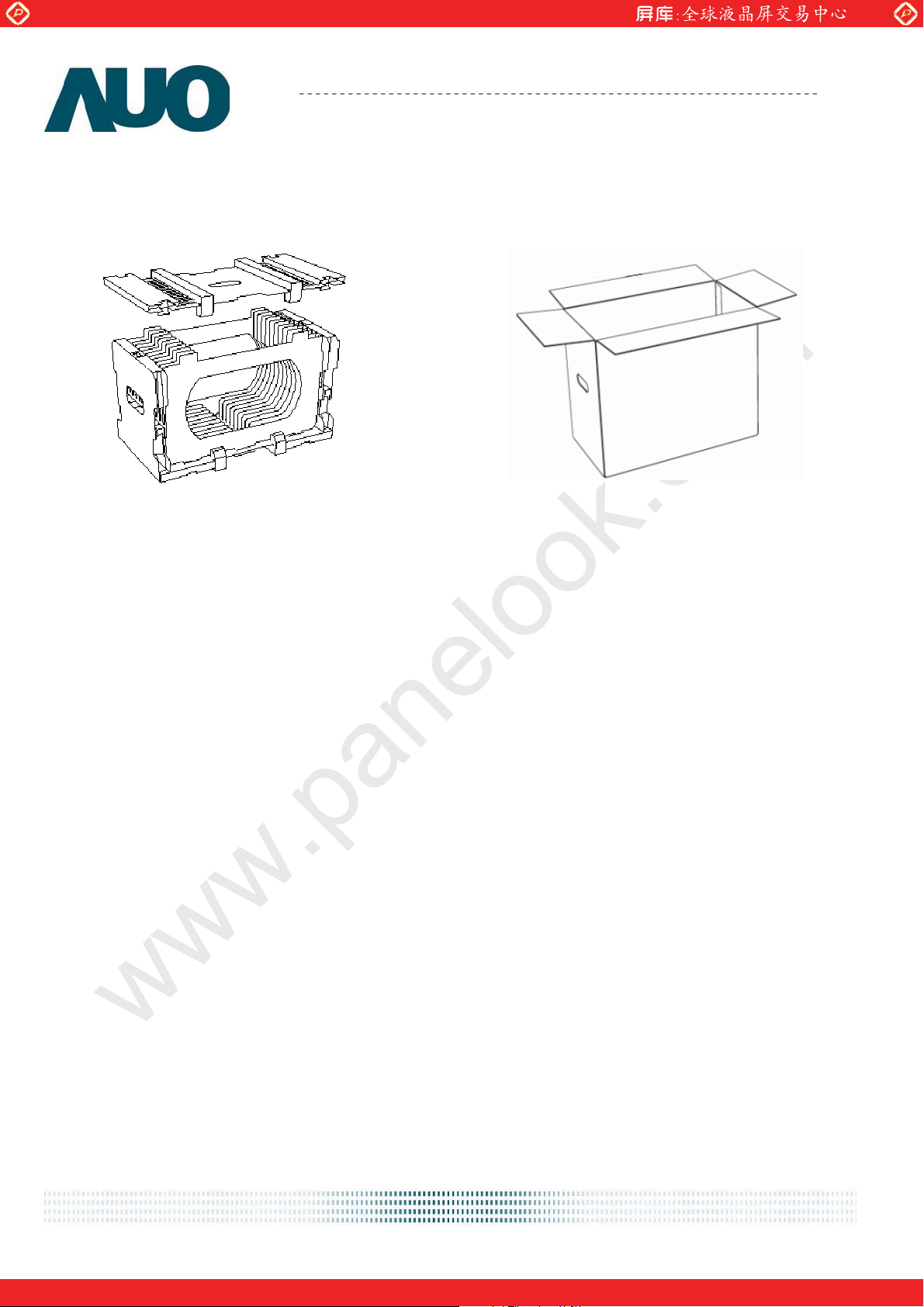
11. Packing Specification
carton հ؆ী֡՚ 519(L)mm* 279(W)mm*330(H)mm, carton+ᒷᓢޗૹၦ 2120g The outside
dimension of carton is 519(L)mm* 279(W)mm*330(H)m m, carton and cushion weight are2120g.
Cushion P/N Κ 84.18M02.013
Carton P/N Κ 81.18M02.004
M185XTN01.0
ᐋ
document version 0.1
ᐋ pallet ؚཥقრቹ
ᐋᐋ
One step solution for LCD / PDP / OLED panel application: Datasheet, inventory and accessory!
ؚཥقრቹ
ؚཥقრቹؚཥقრቹ
www.panelook.com
Page 29
Global LCD Panel Exchange Center
www.panelook.com
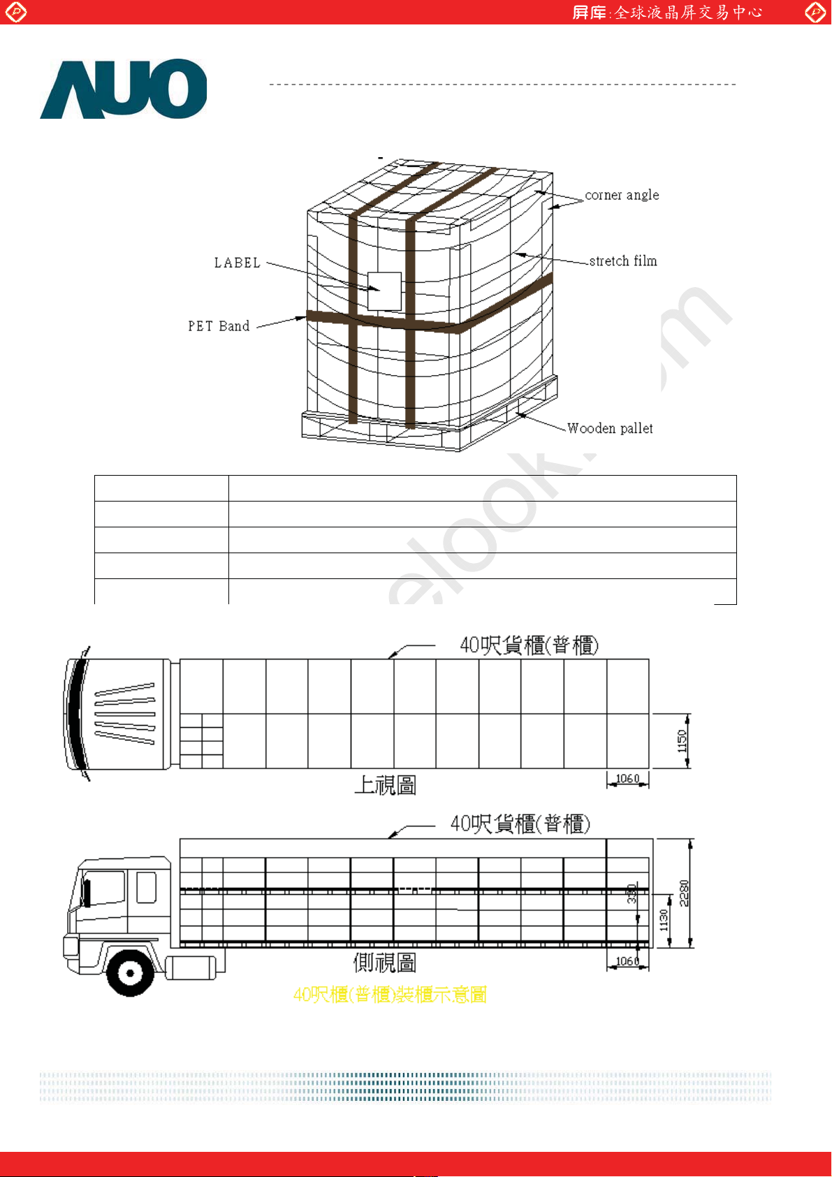
2. Pallet and shipment information
Product Specification
AU OPTRONICS CORPORATION
M185XTN01.0
ຄ឵֡՚
ຄ឵֡՚ʳ
ຄ឵֡՚ຄ឵֡՚
ཥࣨীᇆ
ཥࣨীᇆ/
ཥࣨীᇆཥࣨীᇆ
ഔཥݮڤ
ഔཥݮڤʳ
ഔཥݮڤഔཥݮڤ
ຄഔᦤ
ຄഔᦤ˂ˣ˴˿˿˸
ຄഔᦤຄഔᦤ
ຄ឵ཥࣨᑇ
ຄ឵ཥࣨᑇʳ
ຄ឵ཥࣨᑇຄ឵ཥࣨᑇ
˂ˣ˴˿˿˸ʳʳᐋഔᦤΚˋˋˋˋʳ ᒣʳ ʳ Δཥࣨഔᦤ ˇ ᐋ٥ʳ ˆ˅ʳ ᒣΔᠨᐋཥࣨഔᦤ٥ ˈˈˈˈ ᐋ٥ ˇ˃ ᒣʳ ʳ
˂ˣ˴˿˿˸˂ˣ˴˿˿˸
ʳ
ʳ
ʳ
M20 / 1140 mm * 1060 mm* 138 mm
˧˴˿ʳˣ˴˿˿˸ʳˍʳ
˧˴˿ʳˣ˴˿˿˸ʳˍʳˇˇ
˧˴˿ʳˣ˴˿˿˸ʳˍʳ˧˴˿ʳˣ˴˿˿˸ʳˍʳ
ˇˇʳ˴˿˿˸ʳʳʳʳ ( Κ11pallet * ᐈΚ2 pallet * : pallet )
ˇˇˇˇ
ˇ˃ʵ
ˇ˃ʵʳʳʳʳ
ˇ˃ʵˇ˃ʵ
''''RXEOH
RXEOHˣ˴˿˿˸
RXEOHRXEOH
ˣ˴˿˿˸ʳʳʳʳ
ˣ˴˿˿˸ˣ˴˿˿˸
document version 0.1
One step solution for LCD / PDP / OLED panel application: Datasheet, inventory and accessory!
www.panelook.com
 Loading...