


AC UNISON SOLAR POWER SYSTEM
INSTALLATION GUIDE
Please carefully read these installation instructions.
This document is available on our web site
http://solar.auo.com/?sn=784&lang=en-US&c=238
Thank you for choosing AUO.

AUO AC Unison
[AUO AC Unison Installation Guide] [Page 1 of 44] [February 2012 Rev. 1.0]
Table of Contents
Page
1. Overview-AC Module Installation Components………….…….…………………………2
2. AC Module Planning and Preparation……………………………………….…………….4
2.1 ACPV System Design and Layout…………………………….………………...5
2.2 Accessory Plan and Part Number……………………………………………….12
2.3 Accessory Plan and Part Number…………………………………….………...14
3. AC Unison Module System Installation……………………………………………………15
3.1 AC Cable Termination…………………………………..…………………….......15
3.2 AC Cable Management………………...…………………………………………15
3.3 Accessory Plan and Part Number……………………...……………….…….....16
AUO AC Unison Module Map……………………….………………….…….....17
3.4 Data Logger Installation and Setup………………………………………………..18
4. AUO Solar Web Portal Account Creation…………………………………….……………22
4.1 Creating your Installer or Company Account………………………...…………22
4.2 Create A New Customer Account……………………..…………………………22
4.3 Creating your New Customer Account……………………….………………….23
5. Notice and Safety Instructions……………………………………………………….……..25
6. Additional Information on AC Module Planning & Preparation……...............................31
7. PV System Attachment Mounting Considerations…………………………...……………32
8. Micro-Inverter Specifications………………………………………………………………...34
9. Data Logger……………………………………………………………………………………35
9.1 Data Logger Preparation……………………………………………………..........36
9.2 Data Logger Specifications…………………………………………………………36
9.3 LCD Display Menu Tree…………………………………………………………….37
AUO AC Unison
[AUO AC Unison Installation Guide] [Page 2 of 44] [February 2012 Rev. 1.0]
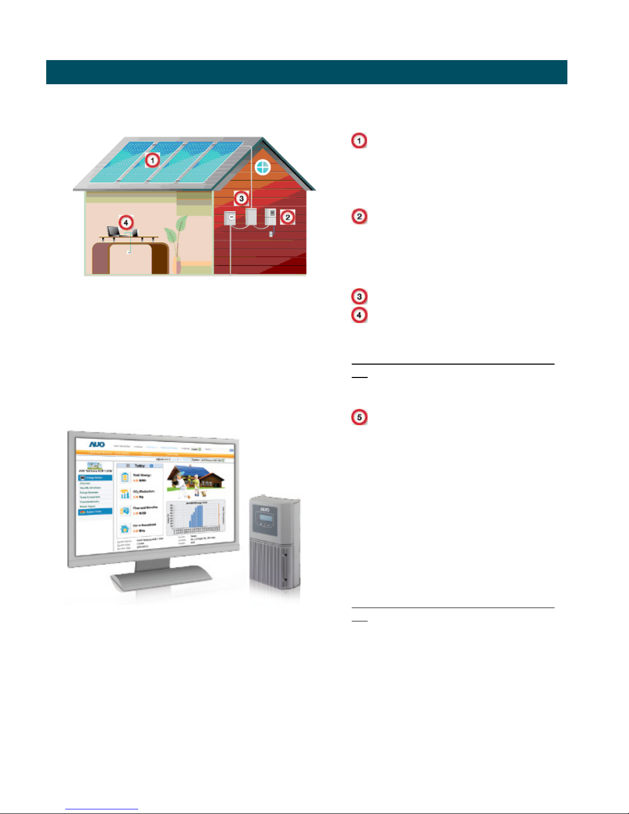
AUO AC Unison Solar Power System -the following diagram illustrates the major component layout for
a typical residential Photovoltaic(PV) system installation.
AUO AC Unison PV modules –our
AC modules
AUO Data Logger(DL) –our data
acquisition system(DAS)
PV Distribution Panel –dedicated
PV distribution panel for AC module
circuits(not to exceed 17 modules per
circuits) and Data Logger circuit(not to
exceed 20A)
Utility Meter Main(1-Phase)
Gateway or Wireless
Router –internet connection, existing or
provided by others
http://solar.auo.com/?sn=905&lang=enUS
AUO Solar Web Portal –high
resolution module and array
performance monitoring
Step1 –one time installer
registration(see your sales
representative for your *Distributor
Code)
Step 2 –installer registers
individual
customer sites
Step 3 –customer permission of
‘Terms and Conditions
http://solar.auo.com/?sn=905&lang=enUS
1. Overview
-
AC Module Installation Components

AUO AC Unison
[AUO AC Unison Installation Guide] [Page 3 of 44] [February 2012 Rev. 1.0]
Plug & Play Installation
• Single Manufacture Warranty
• Standard NEC AC installation practice –similar to appliance installation
• No need to calculate string sizes, a simple limit of 17 modules per 20A branch circuit
• Scalability –easily add modules as time and budget allow
Greater Energy Harvest
Reduced shading losses
3% reduction module mismatch
Increased system availability -single failure does not impact entire system
Safety
No exposure to high voltage DC electricity during installation
No DC arc faults
Ability to turn off power at the module
Cloud Based Monitoring & Communication
Each microinverter communicates with a site gateway and then onto cloud-based application
Provide both the system owner and the installer with a detailed data and information PV system and
individual module performance data
Design and Delivery
• Lower installation costs
No inverter to install, eliminates DC components/field wiring
Less specialized installers needed –labor reduction
More flexible installation
• Higher availability (no single point of failure)
• Reduced design costs -no string design consideration nor limitations
• Scalable – can add modules over time
The AC
Module
Advantage

AUO AC Unison
[AUO AC Unison Installation Guide] [Page 4 of 44] [February 2012 Rev. 1.0]
The critical components of an AC Unison Module:
AC Unison Module voltage ratings
240 Volt AC Single Phase (“split phase”)
L1 to L2 211 to 264 VAC
L1, L2 to Neutral 106 to 132 VAC
2.0 AC Module Planning and Preparation
1 AUO AC Module
1-1 DC-to-AC micro-inverter
1-2 Module Junction Box
1-3 Mid-Cable Receptacle
(Female)
1-4 AC Cable Plug (Male)
2 MCR Bracket
(field installed)
3 M3 Screw
4 M5 Screw
5 End Cap
6 Transition Cable

AUO AC Unison
[AUO AC Unison Installation Guide] [Page 5 of 44] [February 2012 Rev. 1.0]
2.1
ACPV System Design and Layout
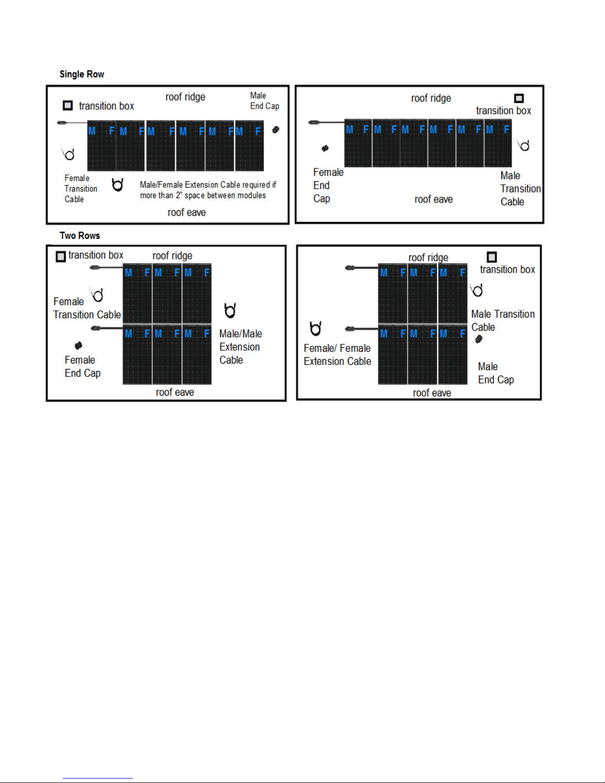
Please see below several of our common module layout examples and ‘best practice’.
AUO AC Unison
[AUO AC Unison Installation Guide] [Page 6 of 44] [February 2012 Rev. 1.0]

AUO AC Unison
[AUO AC Unison Installation Guide] [Page 7 of 44] [February 2012 Rev. 1.0]
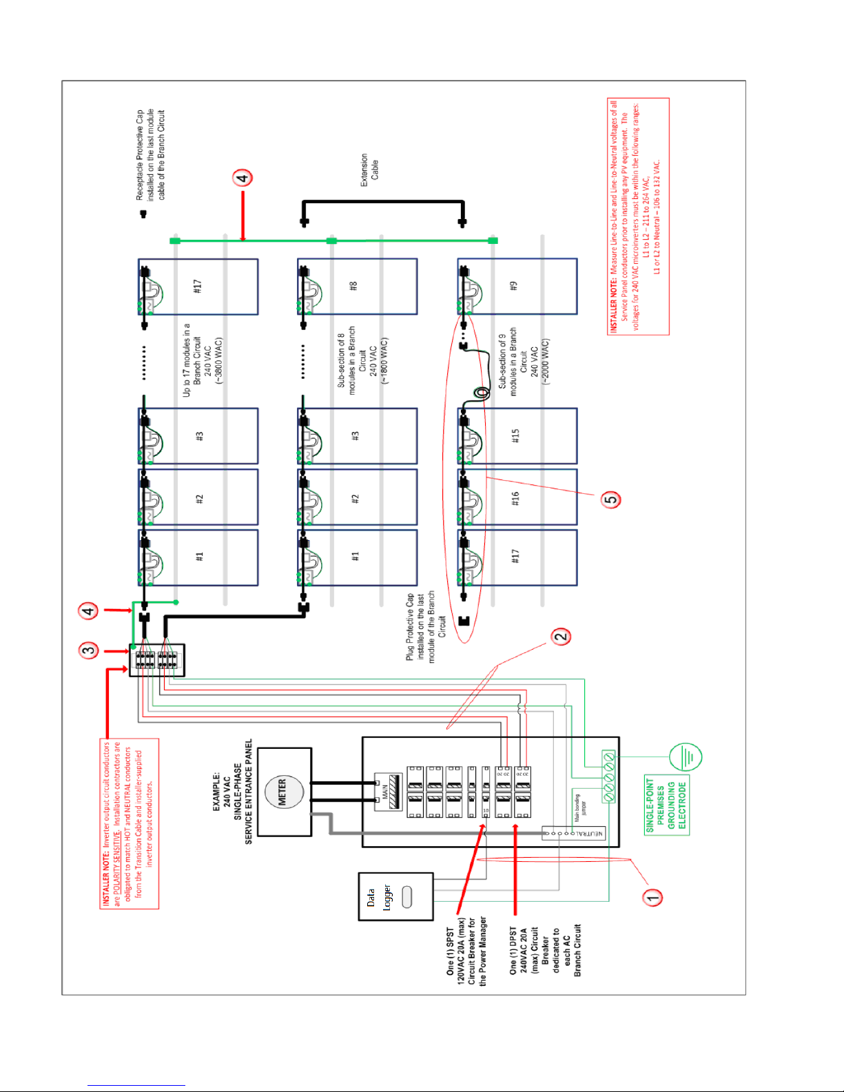
Typical Wire Type:
Use THWN Wire Size of AWG #12 to #16. Data Logger is connected directly to the service panel to optimize Power Line
Communications. Optionally, the Data Logger can be connected to a NEMA 5-15 receptacle near the service panel.
Inverter output circuit:
A single branch circuit (maximum of 17 AC Unison modules per branch circuit) will terminate with a transition cable or an
extension cable that could be routed toward an electrical work box on the roof or another set of AC Unison modules on
another part of the roof. When the installer is routing AC cables out from under the array, the AC cables must be supported
and managed using best electrical practices and proper wire management equipment (e.g. wire tray, hangers, straps, etc.).
Direct to service entrance panel (as shown) or to a sub-panel off a higher rated breaker in the service entrance panel.
Supplied by installation company as part of Balance of System (BOS) components. Typical Wire Type depends on wiring
method to array. Size for 20 amp dedicated branch: minimum 12 AWG but may be larger due to temperature derating in
conduit or voltage drop due to distance. Transient voltage surge suppressor recommended for sites subject to lightning. See
NEC or CEC for AC wiring guidance, breaker placement, and panel loading.
Exterior-rated electrical distribution box with distribution block or terminal strip rated for 240 VAC 20A (supplied by
installation contractor).
Grounding lugs and external ground wires:
The AC cable provides equipment grounding for the AC Unison module only. It is the installer's responsibility to ensure that
any metallic parts in contact with the module (i.e. mounting systems) are provided with a means of equipment grounding
according to the manufacturer’s instructions and local code. Failure to provide proper grounding can void equipment warranty
in the case of lightning strike.
In areas subject to lightning, it is recommended to provide auxiliary grounding between the AC Unison module frame and the
racking to bond all metal together. This can be done with straps or fasteners approved for grounding PV module frames. The
entire array structure should then be connected directly to the ground electrode using a suitably sized copper conductor. (Note:
do not run this conductor in the conduit with the EGC or AC power conductors). Typical Wire Type: Green insulated wire size
must be no smaller than largest conductor in the PV system. If the ground wire is external, use a minimum 6 AWG per NEC or
CEC.
AC Unison module Interconnecting Cables: Exterior-rated AC cable with equipment grounding conductor (EGC) integrated
into the AC Unison module. Cables are rated for disconnect under load and can be used as an NEC disconnect device. Check
with the AHJ for requirements for a separate AC disconnect to be installed next to the PV array.
If the string will continue to another row, then an extension cable is needed. Plug the extension cable into the current module
and place it in the general position to connect to the next module you will install. For rail mount systems, lay the extension
cable over the rails on which the next module will be installed. This ensures that the cable remains under the module for
protection from the sun and uses the rails to keep the cable off the roof surface.

AUO AC Unison
[AUO AC Unison Installation Guide] [Page 8 of 44] [February 2012 Rev. 1.0]
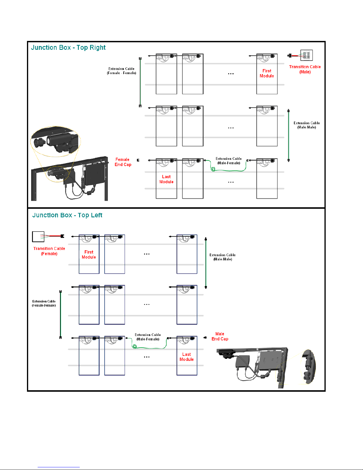
Depending on the system layout, the first and last module in a string would require different male – female preparations. For
the first module, plug the transition cable into the AC cable plug or mid-cable receptacle. For the last module, cover the AC
cable plug or mid-cable receptacle with female or male end cap depending on the system layout. Installer must ensure that the
cable does not touch the roof. Examples are shown below:
AUO AC Unison
[AUO AC Unison Installation Guide] [Page 9 of 44] [February 2012 Rev. 1.0]
AUO AC Unison
[AUO AC Unison Installation Guide] [Page 10 of 44] [February 2012 Rev. 1.0]

AUO AC Unison
[AUO AC Unison Installation Guide] [Page 11 of 44] [February 2012 Rev. 1.0]

AUO AC Unison
[AUO AC Unison Installation Guide] [Page 12 of 44] [February 2012 Rev. 1.0]
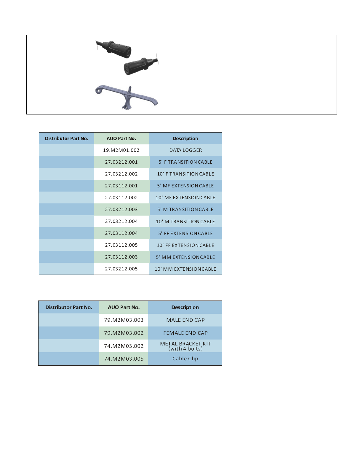
2.2 Accessory Plan and Part Number
The diagrams in this section provide examples of array configurations you might encounter and the types of cables necessary
for various configurations. The following AC wiring accessories are available to assist in any system layouts that you will
encounter.
Part name Description
Male End Cap
- Plugs into the mid-cable receptacle at the end of a string to
protect the cable from dirt and moisture.
- Available in boxes of 250.
Female End Cap
- Covers the interconnecting cable plug at the end of a string to
protect the cable from dirt and moisture.
- Available in boxes of 250.
Transition Cable
(Male)
- Interconnecting cable plug on one end and 100 mm of stripped
wires on the other.
- 20A, exterior-rated 4-wire (L1, L2, N, and Ground) cable.
- Available in 5' and 10' lengths.
- Each cable is shipped with one disconnect tool.
Transition Cable
(Female)
- Interconnecting cable receptacle on one end and 100 mm of
stripped wires on the other.
- 20A, exterior-rated 4-wire (L1, L2, N, and Ground) cable.
- Available in 5' and 10' lengths.
- Each cable is shipped with one disconnect tool.
Extension Cable
(Male-Female)
- Interconnecting cable plug on one end and interconnecting cable
receptacle on the other.
- 20A, exterior-rated 4-wire (L1, L2, N, and Ground) cable.
- Available in 5' and 10' lengths.
Extension Cable
(Male-Male)
- Interconnecting cable plugs on both ends.
- 20A, exterior-rated 4-wire (L1, L2, N, and Ground) cable.
- Available in 5' and 10' lengths.
AUO AC Unison
[AUO AC Unison Installation Guide] [Page 13 of 44] [February 2012 Rev. 1.0]
Extension Cable
(Female-Female)
- Interconnecting cable receptacle on both ends.
- 20A, exterior-rated 4-wire (L1, L2, N, and Ground) cable.
- Available in 5' and 10' lengths.
Disconnect Tool
- Center disconnect pin is inserted into interconnecting plugs,
receptacles, and mid-cable receptacles to safely disconnect
components.

AUO AC Unison
[AUO AC Unison Installation Guide] [Page 14 of 44] [February 2012 Rev. 1.0]
2.3 AC Unison Field Preparation
Step 1 Attach Mid-Cable
Receptacle(MCR) to Module
Framet
Attach the stainless steel (SS) MCR bracket
to the module frame with two M5 screws
(provided). Torque to 20 inch-pounds. Next,
attach the AC Mid-Cable Receptacle harness
to the SS MCR bracket with two M3 screws
(provided). Torque to 20 inch-pound. It is best
to complete steps 1 and Step 2 on the ground
prior to installing the AC Unison modules.
Step 2
First and last module
considerations
For the last module in the circuit, insert the End
Cap into the Mid-Cable Receptacle.
For the first module in the circuit
, connect the
AC cable plug to Transition Table.
*For additional information on AC Module Planning&Preparation, please see page xx.

AUO AC Unison
[AUO AC Unison Installation Guide] [Page 15 of 44] [February 2012 Rev. 1.0]
3.1 AC Cable Termination
Remove the protective sticker located on
the Mid-Cable Receptacle(MCR) and
connect this receptacle to the AC cable of
the next module. Press the Male – Female
plug firmly into the receptacle until you
hear the lock click into place. Continue to
connect subsequent modules to the end
of the string.
3.2 AC Cable Management
The following diagram shows a system of three AC Unison modules. The AC cables are secured to the
module frames with stainless steel Cable Clips at the recommended locations below. Limit module
spacing to 1 inch maximum. Please ensure that all AC wiring is well secured and not in contact with the
roof surface.
3.0 AC Unison Module System Installation
Firmly press male AC cable into rigid female
MCR AC receptacle
1 inch maximum
mod
ule spacing

AUO AC Unison
[AUO AC Unison Installation Guide] [Page 16 of 44] [February 2012 Rev. 1.0]
3.3 Module Layout Map and Serial Number Tracking
Please remove one serial
number(SN) sticker located on
the Mid-Cable Receptacle of
each AC Unison Module and
place it on the AUO AC Unison
Map. Your Module Map will
provide the necessary AC
module layout information during
the final step of creating your
customer account on the AUO
Solar Web Portal. This will
provide both array and module
level performance monitoring.
System Layout Example: 5 modules in Circuit A and 3 modules in Circle B
* Limit each branch circuit to 20A and 17 modules
* Module Layout Example: Circuit A = 5 modules and Circuit B = 3 modules
PV
Distribution
Panel

AUO AC Unison
[AUO AC Unison Installation Guide] [Page 17 of 44] [February 2012 Rev. 1.0]
AUO AC Unison Module Map
Installer Name ________________________ AUO Module(Wp) ________________
Project Name _________________________ No. of Modules _________________
Project Location State____ Zip Code __________ PV System Size _________________
Date of Installation _________________________ Data Logger SN _________________
*NEC branch circuit limit to 20A and 17 AC modules per circuit.
Cir_A Cir_B Cir_C Cir_D Cir_E
1
2
3
4
5
6
7
8
9
10
11
12
13
14
15
16
17

AUO AC Unison
[AUO AC Unison Installation Guide] [Page 18 of 44] [February 2012 Rev. 1.0]
3.4 Data Logger Installation and Setup
The AUO Data Logger(DL) is a gateway device that utilizes Power Line Communications (PLC) to
collect status and performance data from AC Unison modules. The Data Logger retrieves module level
production data at 5 minute intervals and then forwards the aggregated data to the AUO Solar Web
portal at 15 minute intervals. Our data logger is NEMA 3R rate and suitable for outdoor applications.
The AUO Solar Web Portal is a cloud based data management system that enables customers to
register, create and monitor their photovoltaic(PV) systems.
http://solar.auo.com/?sn=905&lang=en-US
Step 1 Data Logger Component Verification
Please ensure that you have the following components.
*Components 4 and 5 are provided by installer

AUO AC Unison
[AUO AC Unison Installation Guide] [Page 19 of 44] [February 2012 Rev. 1.0]
Step 2 Remove the Data Logger
Covers
Remove the screws and the front cover of the
Data Logger. Then remove the screws and
blue AC terminal cover .
Step
3 Data Logger Terminations
AC Power Termination(1-Phase)
For 1-phase AC applications, feed cable
through the bottom left opening of Data Logger
housing and the rubber grommet to reach the
AC terminal. Connect the L1 terminal to the
“Hot”(black) wire of split-phase system and, the
N terminal to the neutral(white) wire. Do not
exceed NEC 20A and 17 module branch circuit
protection limit.
Ethernet Termination(RJ45)
Use T568B to terminate the CATV+ ethernet
patch cable to connect the network socket to a
10/100Base-T router or broadband gateway.
Before terminating your RJ45, please note the
following standard T568B pin out and color code
sequence. *It is always a good idea to validate or
test your RJ45 terminations with standard
network cable testing equipment.
*For best results please hardwire the Data Logger to the PV Distribution Panel.
Please do not ground or bond the Data Logger

AUO AC Unison
[AUO AC Unison Installation Guide] [Page 20 of 44] [February 2012 Rev. 1.0]
Step 4 Mounting the Data Logger
With the mounting pins pointing up, first secure
the mounting bracket to the wall with two screws
provided and, suitable anchors if needed. Then,
mount the Data Logger as shown securing the
Data Logger in place by inserting the provided
screws in the anchor holes as indicated. The Data
Logger is rated NEMA 3R and suitable for outdoor
use. Mount vertically and do not place in direct
sunlight.
*Torque screws to 20 in-lbs
Step 5 Replace protective covers
First replace the blue AC terminal cover securing the screws. Then replace the front cover and secure
the screws as shown in Step 4, torque screws to 20 in-lbs
Step 6 Data Logger Start-up
The Data Logger will automatically boot-up when it
detects utility power. The Data Logger will display the
“PLEASE WAIT” message during its initialization
process. Please allow about 20 minutes for the Data
Logger to fully start up. Do not interrupt the AC
power supply during the boot-up sequence. Once
the initialization process has completed, the LCD
displays the shown “HOME SCREEN”.
Step 7 AC Unison Module Discovery
Navigate the Data Logger’s menu by pressing for
the next menu and to enter/select. Please enter
the “Setup” menu and select the “DISCOVER” function.
After this “Discovery” process, the LCD will display the
number of modules discovered and real-time power
generation.
[Module Count] [Today’s Power Generation] [Internet
Handshake]

AUO AC Unison
[AUO AC Unison Installation Guide] [Page 21 of 44] [February 2012 Rev. 1.0]
Step 8 Verify Internet Connection
The right side of Home Screen will display “COMM”
indicating a reliable internet connection or valid
connectivity handshake from the Data Logger to the
existing broadband gateway or network router. A
‘NOCOMM’ reading indicates an unreliable or failed
network handshake between the Data Logger and the
network gateway. ‘Refresh IP’ through the Data
Logger ‘Communication’ menu. Exit the
‘Communication’ menu returning to the ‘Home Screen’.
‘COMM’ should now be displayed on the Home
Screen, indicating a reliable network connection.
[Module Count] [Today’s Power Generation] [Internet
Handshake]

AUO AC Unison
[AUO AC Unison Installation Guide] [Page 22 of 44] [February 2012 Rev. 1.0]
The AUO Solar Web Portal is a cloud-based data acquisition and management system that enables high
resolution PV module and system creation, customization, monitoring and reporting of your new installed
ACPV system. Please refer to the AUO Solar Web Portal User guide for additional setup and operation
detail.
4.1 Creating your Installer or Company Account
If this is your first time using AUO Solar Web Portal, your first step is to register a New Installer account.
Your authorized AUO Distributor or Dealer will provide your installer or company account registration
code. After signing up, installers should receive an email with your default login password for the
registered account. Please carefully read the Terms of Use. AUO Solar Web Portal URL
http://solar.auo.com/?sn=905&lang=en-US
4.2 Create A New Customer Account
Login to your newly created installer account http://solar.auo.com/?sn=905&lang=en-US . Next, select
the All Systems to Register A New System. Enter the 15 digit serial number from the installed AUO
Data Logger. The serial number can be retrieved from one of three(3) locations: 1) the bottom of the Data
Logger, 2) through the front panel LCD on the Data Logger and 3) the label on outside of the Data Logger
box
4.0
AUO Solar Web Portal Account Creation

AUO AC Unison
[AUO AC Unison Installation Guide] [Page 23 of 44] [February 2012 Rev. 1.0]
4.3 Creating your New Customer Account
Step 1 Create Profile
-Select the Create
Profile tab, enter the details of the AC Unison
PV system installation. Be certain to Save
each step in the process before you proceed
to next step in this 3 step process
Step 2 AC Unison Configuration
drag
and drop AC modules as needed to create
an array layout
. Place the modules by
serial number azimuth and tilt angle in
accordance with your project site Module
Map. the panels as they are physically
installed. Please “Save” and proceed to the
next step as directed on-screen.

AUO AC Unison
[AUO AC Unison Installation Guide] [Page 24 of 44] [February 2012 Rev. 1.0]
Step 3 Sign up a New Account
. First
enter the email address and name of the PV
system owner. A system generated
password will be sent to the account holders
email address.
The system registration process has been
completed and the registered system is now
listed under the All Systems tab. This system
will remain Locked until the system owner
logs in to the AUO Solar Web Portal and
activates their new account.

AUO AC Unison
[AUO AC Unison Installation Guide] [Page 25 of 44] [February 2012 Rev. 1.0]
This section contains important information and instructions to safely install an array of alternating current photovoltaic solar
modules (AC Unison module) and the Data Logger. Failure to follow these instructions can result in equipment damage or
failure, or personal injury, and may void the system warranty, and/or property damage.
Important safety instructions for AC Unison modules
The nationally recognized testing lab (NRTL) performing the listing or certification on an AC Unison module assembly that
includes this micro-inverter might require the following statements to be included in the AC Unison module installation
instructions. There shall be no substitute for the words "CAUTION", "WARNING", or "DANGER" in the text of the following
instructions. Exception: The words "WARNING" or "DANGER" may be used in lieu of "CAUTION". When used, these words
shall be in upper case. Installation and field service is to be performed only by qualified, trained personnel with the necessary
skills and knowledge to work on this type of electrical equipment.
- Perform all electrical installations in accordance with any local codes, the National Electrical Code (NEC) ANSI/NFPA 70
for US installations, or the Canadian Electrical Code Part I, CSA C22.1 for Canada.
- This unit or system is provided with fixed trip limits and shall not be aggregated above 30 kW on a single Point of Common
Connection.
Voltage and frequency limits for utility interaction C
Simulated utility source
Condition
Voltage (V) Frequency (Hz)
Maximum time (sec) (cycles) at 60 Hza before
cessation of current to the simulated utility
A < 0.50V
nor
b
Rated 0.16
B 0.50V
nor
b
<V<0.88V
nor
Rated
2
C 1.10V
nor
b
<V<1.20V
nor
Rated
1
D
1.20V
nor
≦
V
Rated
0.16
E Rated f> Rated+0.5 0.16
F Rated F< Rated-0.7 0.16
a – Non-adjustable maximum clearing times
b – Nominal voltage equals 120V phase to neutral
c – Trip limit accuracy: Voltage-±2.5% based on 120V nominal, frequency-±2.5 Hz
- This AC Unison module is intended for operation in an environment having a maximum ambient temperature of 45°C.
- Work with the local electric company and authorities having jurisdiction (AHJ) before, during, and after the installation of
the solar electric system. The following are examples of possible requirements the electric company might have regarding
the installation:
An upgrade of the existing meter
A readily accessible AC disconnect and a diagram showing its placement
An inspection or approval before connecting the system to the utility grid
Qualified personnel or electric company employee to connect the system to the utility grid
5.0
Notice and Safety Instr
uctions

AUO AC Unison
[AUO AC Unison Installation Guide] [Page 26 of 44] [February 2012 Rev. 1.0]
- WARNING: Shock Hazard. AC wiring is energized by both utility dedicated branch circuit(s) and AC Unison modules rated
as "Utility Interactive". Opening the array's dedicated branch disconnect will also cause the AC Unison modules to stop
producing power. Proper safety procedures must be followed when installing or accessing the dedicated branch circuit
wiring, which includes unplugging the AC Unison modules from the dedicated branch circuit.
- The AC Unison module interconnecting cable system includes an internal equipment grounding conductor (EGC)
connected to each module through pluggable connectors with a longer ground pin.
- The AC Unison module does NOT require a grounding electrode conductor (GEC), and the neutral within the AC Unison
module is isolated from ground.
- The AC Unison module must be connected to a dedicated branch circuit from an AC supply system with the neutral
referenced at the building or structure service entrance.
- The connector on the AC interconnecting cables is rated for disconnect under load and can be used as an NEC
disconnect device. Some authorities having jurisdiction (AHJ) may require a separate disconnect next to the AC Unison
module system as well as a readily accessible disconnect.
- The AC cables and connectors are listed for outdoor use with AC Unison module applications and are rated for 20A, and
with insulation rated to a maximum temperature of 90°C.
- The AC dedicated branch circuit wiring from the readily accessible disconnect to the AC Unison module array must
include an equipment grounding conductor (EGC) run in the same raceway or cable as the AC circuit conductors. This
EGC must be connected to the green colored conductor of the AC Unison module interconnecting cable system, transition
cable, using suitable wiring devices.
- The AC Unison module interconnecting cable system provides an internal EGC for grounding the AC Unison modules only.
Other metal structures, such as mounting systems, must be grounded per code.
- If a module is removed from within the string, it is recommended that you bridge the gap in the string using an AC
extension cable. Inserting an extension cable maintains ground continuity to subsequent modules in the string. Other
auxiliary grounding methods may be used.
- The metal components of the AC Unison module, including frame and micro-inverter, can reach temperatures of
approximately 80°C or more under extreme environmental conditions. To reduce risk of burns, use appropriate safety
procedures when handling.
- CAUTION: To reduce the risk of fire, connect only to a circuit provided with a dedicated 20 amperes maximum over
current protection in accordance with the National Electrical Code, ANSI/NFPA 70.
- No more than 17 AC Unison modules can be connected to a single dedicated branch circuit.
- The AC Unison module output is Utility Interactive.
- To provide proper ventilation to the underside of the module, install modules with a minimum space of 1 inch between the
bottom of module and the mounting surface. The 1 inch is the minimum for the inverter CSA certification. However,
additional distance might be required to maintain a module back sheet temperature less than 85°C.
- During shipping, the mid-cable receptacle is securely fastened to prevent movement. Use caution when unpacking the
module to ensure the mid-cable receptacle does not swing loose and cause damage to the module back sheet.
- The installer must ensure that the AC cables and mid-cable receptacles are supported (will not sag to the roof or module
support structure) and are protected from excessive stress on the cord grip at the base of the mid-cable receptacle.
The AC Unison module is provided with an integral micro-inverter and is NRTL listed as an assembly for outdoor PV
applications. There is no direct current (DC) field wiring required and the integral micro-inverter has no serviceable parts inside.
The following caution is provided as part of the micro-inverter certification:

AUO AC Unison
[AUO AC Unison Installation Guide] [Page 27 of 44] [February 2012 Rev. 1.0]
CAUTION - Risk of Electric Shock!
- Do not remove micro-inverter’s cover. No user serviceable parts inside. Refer servicing to qualified service personnel.
- Both AC and DC voltage sources are terminated inside this equipment. Each circuit must be individually disconnected
before servicing the micro-inverter.
- When the photovoltaic module is exposed to light, it supplies a DC voltage to the micro-inverter.
- When managing AC Unison module cables within the array, the installer must ensure they do not bend the cables beyond
their bend radius tolerances. For the AC Unison module cable, the installer must maintain a bend radius of 4 x cable O.D.
or greater.
Miscellaneous instructions for AC Unison modules
- Do not install AC Unison modules in the rain, snow or windy conditions. Tools must be dry.
- Artificial sunlight should not be concentrated upon the AC Unison module. Do not expose AC Unison modules to sunlight
concentrated with mirrors, lenses or other means.
- Use appropriate safety equipment (insulated tools, insulated gloves, etc) when working on any wiring.
- Do not use damaged or defective AC Unison modules. Place all damaged or defective modules in a carton to avoid
exposure to light. Even damaged or defective modules can produce electricity.
- Roof mounted AC Unison modules are to be mounted over a fire resistant roof.
- Avoid uneven shade on the AC Unison module surface. Shaded cells may become hot (“hot spot” phenomenon) which
may result in permanent damage to the module (e.g., solder joints may peel off).
- Do not clean the glass surface with chemicals or high pressure water spray.
- Do not cover the water drain holes of the frame. There is a risk of frost damage when the frame is filled with water.
- AC Unison modules are heavy. Handle with care. Keep children away from the system while installing.
- Do not expose the AC Unison module to excessive loads on the surface of the AC Unison module or twist the frame. The
glass may break.
- Do not stand or step on the AC Unison module. The glass may be slippery, and there is a risk of injury or electric shock if
glass is broken.
- Do not hit or put excessive load on the glass or back film. PV cells may break.
- To avoid damage to the back sheet, do not scratch or hit the back sheet.
- To avoid damage to the junction box, do not hit the junction box; do not pull the cables.
- Do not scratch the output cable or bend it with force. The insulation of the output cable may break which may result in
electricity leakage or shock.
- Do not pull the output cable excessively. The output cable connection may become loose and cause electricity leakage or
shock.
- Do not drill holes in the frame. It may compromise the frame strength and cause corrosion of the frame.
- Do not touch the AC Unison module with bare hands. The frame of the AC Unison module has sharp edges and may
cause injury. Wear suitable gloves, such as leather gloves with padding in the palm and finger areas.

AUO AC Unison
[AUO AC Unison Installation Guide] [Page 28 of 44] [February 2012 Rev. 1.0]
- Do not drop the AC Unison module or allow objects to fall on the AC Unison module.
- Always wear protective head gear, insulating gloves and safety shoes (with rubber soles).
- Due to the risk of electrical shock, do not perform any work if the terminals of the AC Unison module are wet.
- Do not wear metallic jewelry which may conduct electricity and enable electric shock during installation.
- Do not touch the junction box and the end of the output cables (connectors) with bare hands during installation or under
sunlight, regardless of whether the AC Unison module is connected to or disconnected from the system.
- Do not unplug a connector if the system circuit is connected to an operating load.
- Do not damage the back sheet of AC Unison modules when fastening the AC Unison modules to a support by bolts.
- Do not damage the surrounding AC Unison modules or mounting structure when replacing an AC Unison module.
- Use UV resistant materials, wire management hardware to secure cables. Drooping cables may cause various problems,
such as electricity leakage.
- When AC Unison modules are installed on roofs or any other structures above ground, appropriate safety practices should
be followed and appropriate safety equipment should be used in order to avoid possible safety hazards.
- Make sure flammable gases are not generated or present near the installation site.
Grounding and Bonding the AC Unison Cables
The AC cable attached to the micro-inverter and all cables are fully insulated and contain an equipment grounding conductor
(EGC). The full ground path from the transition cable to the module frame follows:
- The transition cable's green conductor is connected to the EGC from the utility dedicated branch circuit.
- All plugs have ground pins that are longer than the circuit pins. This extra length ensures the ground is the first to make
contact when connecting modules and the last to break contact when disconnecting modules.
- The AC ground wire inside the micro-inverter makes a bolted termination to the micro-inverter chassis and is
environmentally sealed.
- The micro-inverter chassis is bonded at the factory to the module frame with stainless steel hardware to provide ground
continuity to the AC Unison module frame.
The AC cable grounding path has been tested by a NRTL. Before an AC Unison module assembly can be labeled with the
NRTL certification mark and shipped from an authorized and inspected factory, each assembly must pass a ground continuity
check to verify electrical continuity from the AC cord ground pin to the AC Unison module frame. The AC cable provides
equipment grounding for the AC Unison module only. It is the installer's responsibility to ensure that any metallic parts in
contact with the module (i.e. mounting systems) are provided with a means of equipment grounding according to the
manufacturer’s instructions and local code.
Because the DC power is internal to the module, a grounding electrode conductor (GEC) is not required. Because the AC
Unison modules are connected in a “daisy chain” fashion, disconnecting one module from within the string removes power and
ground from subsequent modules in the string. Extreme care should be taken to ensure that no other energized sources are
adjacent to these ungrounded modules, or auxiliary grounding methods must be provided. A best practice for all solar module
installers, especially those in areas with frequent lightning (e.g. greater than 8 lightning strikes per square mile per year), is to
secure each module to the rack using grounding hardware that has been certified to meet requirements for grounding systems.
Connect the entire grounded structure to a grounding electrode system using a dedicated, suitably sized, copper conductor.
Lightning protection for electronic equipment in the home is often accomplished using rapid response SOV’s or MOV’s. These
devices are typically installed at a sub-panel or main service entrance panel where the AC Unison module system has been
connected. Lightning arrestors handle large surges from nearby lightning strikes and surge capacitors control surges that are
too fast or too light for a lightning arrestor to function. Although complete lightning protection systems from companies such as

AUO AC Unison
[AUO AC Unison Installation Guide] [Page 29 of 44] [February 2012 Rev. 1.0]
ABB, APC or Polyphaser can be designed to the practices in your area and installed in the home, more component level
solutions can be purchased from companies like Dehn, Cital or Delta Lightning Arrestors (e.g. Delta LA 300 Series surge
arrestors and CA 300 Series surge capacitors).
NOTE: Proper grounding of the AC Unison module system will ensure full warranty coverage. Although highly recommended,
the installation of auxiliary lightning protection systems / components is not specifically tied to the AC Unison module’s
warranty. The conductor used for lightning protection from the structure to the grounding electrode system must not be run
inside the same conduit that contains the EGC and AC circuit conductors.
FCC Compliance of AC Unison modules and Data Logger
The equipments have been tested and found to comply with the limits for a Class B digital device, pursuant to Part 15 of the
FCC Rules. These limits are designed to provide reasonable protection against harmful interference in a residential installation.
This equipment generates, uses and can radiate radio frequency energy and, if not installed and used in accordance with the
instructions, may cause harmful interference to radio communications. However, there is no guarantee that interference will
not occur in a particular installation. If this equipment does cause harmful interference to radio or television reception, which
can be determined by turning the equipment off and on, the user is encouraged to try to correct the interference by one or
more of the following measures:
- Reorient or relocate the receiving antenna.
- Increase the separation between the equipment and receiver.
- Connect the equipment into an output on a circuit different from that to which the receiver is connected.
- Consult the dealer or an experienced radio/TV technician for help.
Changes or modifications not expressly approved by the party responsible for compliance could void the user’s authority to
operate the equipment.
Safety Certification of Data Logger
ETL listed to UL60950-1 ITE and UL60950-22 for outdoor use.
The Data Logger is not a utility meter, disconnect device, or power distribution device.
Safety instructions for Data Logger
Installation and field service is to be performed only by qualified, trained personnel with the necessary skills and knowledge to
work on this type of electrical equipment. Field service is limited to the components contained in the lower compartment of the
Data Logger.
- Perform all electrical installations in accordance with any local codes, the National Electrical Code (NEC) ANSI/NFPA 70
for US installations, or the Canadian Electrical Code Part I, CSA C22.1 for Canada.
- Suitable for use indoors or outdoors (Type 3R enclosure). Operating ambient from -20°C to 50°C.
- Identification label and power rating for this device are located behind the front access cover.
- Before connecting power, the Data Logger must be securely mounted to an inside or outside wall following the instructions
in this document.
- For permanently connected equipment, a readily accessible disconnect device must be incorporated external to the
equipment.
- The Data Logger can be connected to a branch circuit with any standard size breaker rating up to 20A. The input
operating current is less than 0.1 amps.
- The Data Logger contains internal transient surge protection for connection to the load side of the service entrance AC
panel. For installations in areas at risk of surges generated by high voltage utilities, industry or by lightning, it is

AUO AC Unison
[AUO AC Unison Installation Guide] [Page 30 of 44] [February 2012 Rev. 1.0]
recommended that an external TVSS also be installed.
- Do not attempt to repair the Data Logger. If the Data Logger fails, please return the unit to your distributor for servicing.
Tampering with or opening the upper compartment of the Data Logger voids the product warranty.
- For pluggable equipment, the socket-outlet must be installed near the equipment and must be easily accessible.
- For Data Loggers equipped with a non-detachable power supply cord and a Polarized NEMA 1-15P plug, the plug is used
as the disconnect means.
- The Data Logger's internal circuits are provided with over-current fault protection on the line side only, not on neutral. For
protection against fire and to ensure proper power line communication (PLC) with the modules, a polarized plug must be
used. It is important to ensure that neutral is connected to the correct terminal of the plug and to the Neutral location on
the Data Logger's terminal block.
- The following labels are used on the Data Logger housing:
This label warns of hazardous voltages behind the AC terminal cover that can cause
serious injury or death if the cover is removed. This area is to be accessed only by
qualified, trained personnel with the necessary skills and knowledge to work on this
type of electrical equipment. Disconnect power before opening.
This label warns of immediate danger due to exposed hazardous voltages that can
cause serious injury or death. This area is to be accessed only by qualified, trained
personnel with the necessary skills and knowledge to work on this type of electrical
equipment. Disconnect power before opening.
IEC 60417-5172 symbol for double insulated equipment (CLASS II) which does not
require a protective earthing (equipment grounding conductor) as a means of
providing protection against electric shock.

AUO AC Unison
[AUO AC Unison Installation Guide] [Page 31 of 44] [February 2012 Rev. 1.0]
For the purpose of this document, a circuit is defined as one to seventeen AC Unison modules connected in parallel to a
dedicated 20A branch circuit. An array refers to the entire installation of one or more strings connected to the structure’s AC
service equipment.
- The ideal installation path is to begin closest to the installed transition box and plug in each module as you move away
from the box. Depending on the configuration of your array and the location of the transition box, this path may not be
feasible. For example, in a 2-row configuration, we recommend installing the bottom row first and working up toward the
transition box, which is likely mounted higher up the roof.
- Before connecting AC Unison module system to any premises wiring, check the AC service panel where the AC Unison
module System breaker will be located. Is there enough physical space in the Panel enclosure for the breaker? Is there
enough electrical capacity remaining in the AC Service Panel to handle the AC Unison module system breaker?
- Where is the junction box located in relation to the module that will connect to it?
Whether the box is located to the left or right of the array (as viewed from the ground facing the installed array) determines
which transition cable you need (male or female) and what preparation is needed for the final module in the string. With
the junction or transition box to the left, the transition cable will connect to the plug at the end of the AC cable. Therefore, a
female transition cable is required. The final module in the string will require a protective cap be plugged into the mid-cable
receptacle. With the junction or transition box to the right of the array, a male transition cable is needed, which will plug
into the mid-cable receptacle, and the final module will require additional cable management to secure the end of the AC
cable. Before connecting the transition cable, calculate the distance from the transition box to the module plus the
distance under the module to reach the appropriate AC connector. This will determine the length of transition cable that
you will need.
- Do you need any extension cables? Will the extension cable reach from connector to connector or is it necessary to
modify the standard cable management of one or both modules to make the connection easier?
If the extension cable is running across open roof, another cable management system might be needed to keep the
extension cable off of the roof and protected from the sun. If the distance to be crossed is longer than the length of the
extension cable, you can use more extension cables or transition back to standard building wiring systems to span the
distance. Use a transition cable to connect the module into a junction or transition box and wire according to local and
NEC or CEC standards. The preparation and installation instructions included in this section are general instructions for
installing AC Unison modules on most mounting systems. In some cases, it might be necessary to modify these
instructions to accommodate specific installation requirements.
6
.0
Additional Information on AC Module Planning & Preparation

AUO AC Unison
[AUO AC Unison Installation Guide] [Page 32 of 44] [February 2012 Rev. 1.0]
PV modules should be installed in a location where there is no shading throughout the year. In the northern hemisphere, PV
modules should typically face south, and in the southern hemisphere, PV modules should typically face north. Please make
sure that there are no obstructions in the surroundings of the site of installation. Take proper steps in order to maintain
reliability and safety in case the PV modules are installed in areas that have heavy snow / extreme cold / strong winds /
installations over, or near, water and areas where installations are prone to salt water exposure or on small islands or in desert
areas.
PV modules should be tilted so that the energy production from the PV modules will be maximized on an annual basis. The tilt
angle of the PV module is measured between the surface of the PV module and a horizontal ground surface. AUO PV
modules produce the most power when the sun’s rays strike the module perpendicular to the module surface. To avoid
performance losses in series circuits, ensure that all modules have the same tilt and orientation.
The frame of the module must be connected with the substructure rails (mounting strips) by at least four points. The following
figures illustrate the installation and the mounting area and the position of the mounting hole. Under no circumstances may the
short frame edges be used for anchoring the module. The assembly on the support structure using the pertinent holes and
specific nuts and bolts. The screws should be tightened up to 5.5 Nm (4.1 lb-ft). The module’s frame must not be drilled nor put
under pressure with other securing systems. The air gap must bigger than 45mm.
The following considerations might affect the placement of the mounting system or the alignment of the modules on the
mounting system. However, no attempt is made to describe how to install the mounting system on the roof or how to use
module clamps.
- Mounting rails must be positioned below the micro-inverter. Do not install modules with the micro-inverter resting on the
mounting rail. The frame of the installed module must rest firmly on the mounting rail. Installing a module with the
micro-inverter resting on the rail and uneven contact between the frame and the rail can cause damage to the
micro-inverter and the module.
- When the mid-cable receptacle is attached to the AC Unison module with wire management components, the mid-cable
receptacle extends beyond the edge of the module frame. Mounting rails must be positioned to not interfere with the
mid-cable receptacle.
7
.0
PV System Attachment
Mounting Considerations

AUO AC Unison
[AUO AC Unison Installation Guide] [Page 33 of 44] [February 2012 Rev. 1.0]
Module Type L (mm) W (mm) D1(mm) D2(mm) D3(mm) D5(mm)
PM250M00.0_XXX 1651 992 425 800 942 300
PM250M00.0_XXX 1651 992 175 1300 942 300
Note: XXX = 240 . 245 . 250 . 255 . 260 .
The mechanical loading claimed value is 50 lb/ft2.

AUO AC Unison
[AUO AC Unison Installation Guide] [Page 34 of 44] [February 2012 Rev. 1.0]
Parameter Rating
Output power factor rating 0.99
Operating voltage range (AC) (L-L) a 211 – 264 V
Operating frequency range or single frequency a 59.3 - 60.5 Hz
Number of phases 1 b
Nominal output voltage (AC) 240 V
Normal output frequency 60 Hz
Maximum continuous output current (AC) 0.94 A c
Maximum continuous output power (AC) 225 W
Utility interconnection voltage and frequency trip
limits and trip times
See "Utility Interaction" on page 3
Total Demand Distortion (TDD) /Individual
harmonics (per IEEE 1547)
< 5% (Passed up to 40th harmonic)
Maximum units per 20 amp dedicated branch circuit
17 d
Maximum output fault current (AC) and duration
11.9 A
peak
, 0.52 A
rms
, total duration
13.8 ms
Maximum output overcurrent protection 20 A d
a
See "Utility Interaction"
b
Single-phase requiring two of the phases (L1 and L2) for power production and a neutral for voltage sensing only, per IEEE
1547.
c
Maximum overload current at peak module performance combined with low grid voltage is 1.17A.
d
This is the maximum number of micro-inverters that can be connected in parallel to a single dedicated branch circuit, which is
protected by a circuit breaker rated at 20 A. This number is derived based on the requirements of the National Electrical Code
(NEC) and the current rating of the micro-inverter. If more micro-inverters than this number need to be installed, additional
20-A branches shall be used, keeping the number of micro-inverters on each branch less or equal to this number.
8.0 Micro
-
Inverter Specifications

AUO AC Unison
[AUO AC Unison Installation Guide] [Page 35 of 44] [February 2012 Rev. 1.0]
The AUO Data Logger is a gateway device that uses Power Line Communications (PLC) to collect status and performance
data from AC Unison modules. Using broadband Internet, the Data Logger then forwards the collected data to the Solar
Monitoring System at five minute intervals. When necessary, the Data Logger automatically downloads and installs
enhancements, which can include defect fixes, to the software on the Data Logger or, on rare occasions, to the firmware on
the micro-inverter. No manual intervention is required during the update process. The following diagrams illustrate the exterior
and interior features of the Data Logger.
NEXT button – Moves to the next item in the current
menu
SELECT button – Displays additional submenus or
information
Removable access cover – Provides access to the
field accessible components of the Data Logger
Location for security lock
AC terminal block cover –
Remove this cover to attach the
wires that will connect the Data Logger to the site's electric
service panel.
Warning: This area is to be accessed only by qualified,
trained personnel with the necessary skills and know
ledge
to work on this type of electrical equipment. Disconnect
power before opening.
12-volt power port – For testing purposes, a suitable
12-volt battery can temporarily power the Data Logger and
enable you to verify the module installation before the Data
Logger is wired to a permanent power source.
USB port – Reserved for future use.
RJ45 port – An Ethernet cable can connect the Data
Logger to a nearby network router or to a service provider's
laptop for local access to the Data Logger's web interface.
9.0 Data Logger

AUO AC Unison
[AUO AC Unison Installation Guide] [Page 36 of 44] [February 2012 Rev. 1.0]
Rubber grommet – This grommet provides
weatherproofing protection around the Ethernet cable.
9.1 Data Logger Preparation
Choose a Mounting Location
- An important step in installing the Data Logger is choosing the location. Close proximity to the site's electric service panel
or module aggregation panel ensures the best communications between the Data Logger and the AC Unison modules.
The greater the distance between the Data Logger and the panel, the greater the risk of encountering limited or no
communication with the modules.
- To ensure the best communications and to provide easy access by service providers, we recommend wiring the Data
Logger's AC terminal block directly to a 20 A (max) circuit breaker in the service or aggregation panel used by the AC
Unison modules. In many cases, this might be on an exterior wall, preferably away from direct sunlight, if possible.
- The Data Logger uses DHCP to acquire an IP address. To enable Internet communication between the Data Logger and
the Solar Monitoring System, the Data Logger must be connected to a 10/100Base-T network router using an Ethernet
cable. When connected to the Internet, the Data Logger periodically uploads site- and module-level data to the AUO Solar
Monitoring System. If a network or DHCP is not available, the Data Logger uses its default IP address, 192.168.100.1.
Verify Required Supplies
- Depending on the mounting surface, use appropriate fasteners and anchors capable of supporting 15 lbs of weight. For
Wood, use screws with 3/4" thread length. For outdoors, use galvanized or stainless steel.
- For outdoor wiring, use wet rated wire (e.g. THWN), outdoor-rated 1/2" conduit (metallic, non-metallic, or flexible), and
appropriate conduit for Type 3R enclosures. Requirements in local codes and NEC or CEC standards take precedence
over this list.
- For indoor wiring, use only listed/ certified wiring devices such as NEMA 1-14 polarized plug, SJO two-conductor power
cord and plastic strain grommet for 1/2" conduit hole on bottom of the Data Logger. If mounted on an interior wall, the Data
Logger can be permanently connected by wiring directly to the service panel. The Data Logger can also be wired with a
Polarized NEMA 1-15P style AC plug and plugged into a standard NEMA 5-15R AC outlet. Follow local codes and NEC or
CEC guidelines for permanent connection to a wiring box or electric service panel.
9.2 Data Logger Specifications
The Data Logger is suitable for use indoors or outdoors in temperatures between -20°C and 50°C (-4°F and 122°F). The
exterior housing is rated Type 3R for protection against all weather conditions. The Data Logger can be connected to standard
Type 3R service panels by using 1/2" NPT outdoor conduit.
Communications
With AC Unison modules Power Line Communication
With monitoring system Ethernet with 10/100Base-T router
Power Requirements
Power Supply Direct wire or AC outlet
Power Consumption ~0.1amp
Mechanical Specifications

AUO AC Unison
[AUO AC Unison Installation Guide] [Page 37 of 44] [February 2012 Rev. 1.0]
Dimensions 13.3"L X 7.9"W X 3.5"D
Weight 3.5 lbs
Ambient Temperature Range -20°C and 50°C (-4°F and 122°F)
Enclosure Environmental Rating Type 3R
Other
Compliance UL60950-1 ITE, UL60950-22 Outdoor Use, FCC Part 15 Class B,
9.3 LCD Display Menu Tree
The following table defines the various screens available through the Data Logger's LCD interface. This interface is most
commonly used by the installer to configure the site after modules have been installed or by a service provider performing
maintenance at the site.
Use the two buttons below the LCD interface to navigate through a set of topic menus that provide access to information or
setup controls. Press the arrow button ( ) to move through the menus. Press the checkmark button ( ) to select a topic
and begin viewing information. Press the arrow button ( ) again to move through the information in the selected topic.
Pressing the arrow button ( ) on the EXIT screen returns you to the first menu item in the current topic menu. Pressing the
checkmark button ( ) on the EXIT screen returns to the topic menu.

AUO AC Unison
[AUO AC Unison Installation Guide] [Page 38 of 44] [February 2012 Rev. 1.0]

AUO AC Unison
[AUO AC Unison Installation Guide] [Page 39 of 44] [February 2012 Rev. 1.0]
Main Menu
The table below describes the top-level menu items in the LCD interface. Use the arrow button ( ) to scroll through the items
in this table. Use the checkmark button ( ) to select the menu.
Menu Description
Press to go to...
Home screen appears when Data
Logger is fully initialized.
Number of discovered modules.
Total amount of power generated
by all modules at the time of the last
data reading.
COMM = Connected to AUO Solar
Monitoring System, NOCOMM = Not
connected to AUO Solar Monitoring
System.
Information about the Data Logger. "Device Information Menu"
Information about each module that is
monitored by this Data Logger.
"Module Information Menu"
Current performance statistics for the
array.
"Site Information Menu"
Information about communications with
the Data Logger.
"Communications Menu"
Menu for discovering the installed
modules.
"Setup Menu"
AUO AC Unison
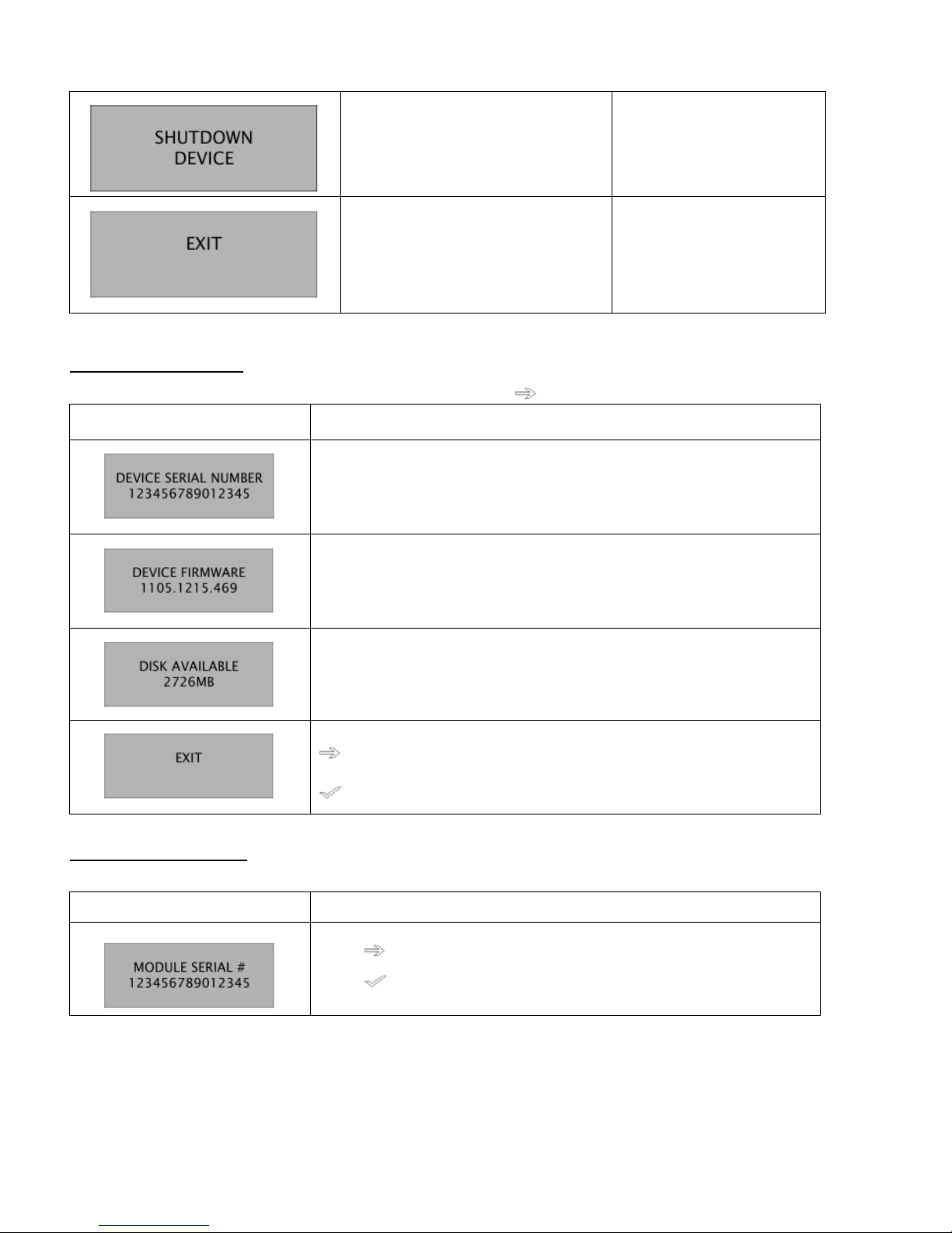
[AUO AC Unison Installation Guide] [Page 40 of 44] [February 2012 Rev. 1.0]
Shuts down the Data Logger software
before disconnecting from power
supply.
"Shutdown Menu"
Scrolls through the menus.
Exits the main menu and
returns to the Home screen.
Device Information Menu
This menu provides basic information about the Data Logger. Press to scroll through the menus.
Menu Description
Displays the serial number of the Data Logger.
Displays the version number of the installed firmware.
Displays the amount of memory still available on the SD card.
Scrolls through the menus.
Exits the information screens and returns to Device Information.
Module Information Menu
This menu provides information about each module in the installation.
Menu Description
Press to scroll through the list of serial numbers.
Press
to view information about this module. The remainder of this
table shows the information available for each module.

AUO AC Unison
[AUO AC Unison Installation Guide] [Page 41 of 44] [February 2012 Rev. 1.0]
Displays the version number of the firmware installed on the inverter
attached to the module.
Displays the current power output of the module.
Displays the DC volts currently produced by the solar module.
Displays the DC amps currently produced by the solar module.
Displays the date and time the module last reported data to the Data
Logger.
Exits the information screens for the selected module and returns to Module
Serial No.
Site Information Menu
This menu provides information about the overall performance of the site.
Menu Description
Displays the amount of energy produced today.
Displays the total energy produced over the lifetime of the array.
Displays the frequency of the electric grid at the time of the last data
reading.
Displays the voltage of the electric grid at the time of the last data reading.

AUO AC Unison
[AUO AC Unison Installation Guide] [Page 42 of 44] [February 2012 Rev. 1.0]
Scrolls through the menus.
Exits the information screens and returns to Site Information.
Communications Menu
This menu provides the IP address and MAC address of the Data Logger as well as the date and time that the Data Logger
last communicated with the monitoring system.
Menu Description
Displays the IP address of the Data Logger.
Press to acquire a new IP address or to renew the current IP address.
An interim screen displays the progress of the refresh and returns the
Device IP Address Screen.
Displays the MAC address of the Data Logger.
Displays the date and time that data from the modules was last transmitted
to the monitoring system.
Scrolls through the menus.
Exits the communication information screens and returns to
Communications.

AUO AC Unison
[AUO AC Unison Installation Guide] [Page 43 of 44] [February 2012 Rev. 1.0]
Setup Menu
The submenu in this menu enables you to discover newly installed AC Unison modules.
Menu Description
Press to begin discovering modules. An interim screen displays
the discovery progress and returns the next screen.
Press to move to the EXIT screen.
Scrolls through the menus.
Exits the information screens and returns to Setup.
Shutdown Menu
This menu shuts down the Data Logger device. To restart the device, cycle the power supply by unplugging the Data Logger
and then plugging it back in or by flipping the circuit breaker.
Menu Description
Press to begin the shutdown process.
Press to choose the correct response to the confirmation question,
then press . Selecting “Yes” continues the shutdown.
The screen goes blank when the Data Logger is off.
 Loading...