

Page 1

www.auna-multimedia.com
C-500
Auto-Endstufe
Car Hifi Amplifier
10032117 10032118 10032119
Page 2

2
Technische Daten
Sehr geehrter Kunde,
wir gratulieren Ihnen zum Erwerb Ihres Gerätes. Lesen Sie die folgenden Anschluss- und
Anwendungshinweise sorgfältig durch und befolgen Sie diese, um möglichen technischen Schäden
vorzubeugen. Für Schäden, die durch Missachtung der Sicherheitshinweise und unsachgemäßen
Gebrauch entstehen, übernehmen wir keine Haftung.
Artikelnummer/
Modell
10032117 10032118 100321119
Ausgänge
2 Kanäle 4 Kanäle 6 Kanäle
Max. Ausgangsleistung
1000 W 2000 W 3000 W
Hochpass
50 Hz- 500 Hz
Tiefpass
50 Hz - 250 Hz
Signal-Rausch-Abstand
90 dB
Frequenzgang
10 Hz - 30 kHz
Eingangsempndlichkeit/
Impedanz
120 mV - 1.0 V
10 kΩ
Lastimpedanz
2-8 Ω
Dämpfungsfaktor
>120
Bassanhebung
(50 Hz) 0/+6/+12 dB
Stromversorgung
10,5 - 15 V
Abmessungen
200x250x52 mm 200x280x52 mm 350x250x52 mm
Page 3

3
Sicherheitshinweise
Stromversorgung
• Schließen Sie das +12-V-Stromkabel erst an, wenn alle anderen Kabel verbunden sind.
• Stellen Sie sicher, dass die Masseleitung des Gerätes sicher an einer Metellstelle am Fahrzeug anliegt.
• Wenn Sie das Autoradio ohne den Remote-Ausgang auf den Verstärker vewenden, verbinden Sie die
Remote-Eingangsklemme (REM OTE) mit dem Stromversorgungszubehör.
• Verwenden Sie das Stromkabel mit einer befestigiten Sicherung (40 A).
• Gewährleisten Sie, dass die Kabel zum +12-V- und Masseanschluss einen größeren Querschnitt als 5
mm
2
haben.
Allgemeine Sicherheitshinweise
• Dieses Gerät ist ausschließlich für den Anschlusss an eine 12-V-Stromversorung geeignet.
• Verwenden Sie Lautsprecher mit einer geeigenten Impedanz (2 - 16 Ohm, Stereo).
• Schließen Sie keine Aktiv-Lautsprecher (mit eingebautem Verstärker) an.
• Montieren Sie den Verstärker nicht in Bereichen, wo er
◦ hohen Temperaturen ausgesetzt ist (z. B. durch direkte Sonneneinstrahlung oder durch die
Heizung).
◦ Regen oder Feuchtigkeit ausgesetzt ist.
◦ der Staub oder Schmutz ausgesetzt ist.
• Wenn das Auto in der direkten Sonne geparkt wird und die Temperatur im Auto beträchtlich steigt,
lassen Sie es vor der Verwendung abkühlen.
• Achten Sie beim waagerechten Einbau des Gerätes darauf, die Rippen mit einem Teppich o. Ä.
abzudecken.
• Wenn die Endstufe zu dicht am Autoradio monitert wird, kann es zu Interferenzen kommen.
Platzieren Sie in dem Fall den Verstärker weiter vom Radio entfernt.
• Falls das Gerät nicht mit Strom versorgt wird, die Anschlüsse überprüfen.
• Der Verstärker verwendet einen Schaltkreisschutz, um bei einer Fehlfunktion die Transistoren und
Lautsprecher zu schützen. Versuchen Sie nicht, den Schaltkreisschutz zu testen, indem Sie den
Kühlkörper abdecken oder das Gerät elektrisch überlasten.
• Verwenden Sie den Verstärker nicht mit einer schwachen Autobatterie, da die optimale Leistung von
einer guten Stromversorgung abhängt.
• Halten Sie die Lautstärke auf einem moderaten Niveau, so dass Sie auch noch die Laute außerhalb
Ihres Fahrzeugs wahrnehmen.
Schaltkreisschutz
Dieser Verstärker ist mit einem Schutz ausgestattet, der in folgenden Fällen funktioniert:
◦ Das Gerät ist überhitzt.
Page 4

4
◦ Es wird Wechselstrom erzeugt.
◦ Die Lautsprecheranschlüsse haben einen Kurzschluss.
Die Notaus-Leuchte geht an, wenn das Gerät sich abschaltet. Wenn dies geschieht, schalten Sie das
angeschlossene Geräte ab und nden den Grund für die Fehlfunktion heraus. Wenn der Verstärker
überhitzt ist, warten Sie, bis das Gerät sich wieder abgekühlt hat, bevor Sie es wieder einschalten.
Anschlüsse
Vor dem Anschließen Folgendes beachten:
• Nehmen Sie vor dem Anschluss die Masse von der Autobatterie, um Kurzschlüsse zu vermeiden.
• Achten Sie darauf, dass die Lautsprecher eine entsprechende Leistung aufweisen. Wenn Sie
Lautsprecher mit einer zu geringen Belastbarkeit anschließen, können sie beschädigt werden.
• Verbinden Sie die "- Klemmen" der Lautsprecher nicht mit der Karosserie des Autos und verbinden Sie
auch die „- Klemme“ des rechten Lautsprechers mit der des linken Lautsprechers.
• Legen Sie die Eingangs- und Ausgangskabel von der Zuleitung der Stromversorgung entfernt, da
sonst Interferenzen entstehen.
• Dieses Gerät ist ein leistungsfähiger Verstärker. Daher kann er nicht sein volles Potential ausschöpfen,
wenn er mit den voreingebauten Kabeln der Autolautsprecher betrieben.
• Wenn Ihr Auto mit einem Computer-/Navigationssystem ausgestattet ist, trennen Sie nicht die Masse
von der Autobatterie, da der Computerspeicher dann gelöscht werden könnte. Um Kurzschlüsse beim
Herstellen von Verbindungen zu vermeiden, trennen Sie die Zuleitung für den 12-V-Stromanschluss,
bis alle anderen Verbindungen hergestellt sind.
Austausch der Sicherung
• Falls die Sicherung durchbrennt, überprüfen Sie die Stromanschlüsse und setzen eine neue Sicherung
ein. Wenn die Sicherung nach dem Austausch wieder durchbrennt, kann eine interne Fehlfunktion
vorliegen. Wenden Sie sich in einem solchen Fall an eine Werkstatt.
• Die neue Sicherung muss zum Verstärker passen und den Angaben an der Sicherungshaltung
entsprechen. Verwenden Sie nie eine Sicherung mit einer Stromstärke, die den Angaben der
Gerätesicherung übersteigt, da das Gerät sonst beschädigt werden könnte.
Page 5
5
Schaltkreis
++++
----
++++
----
++++
----
3CH
HHC4C4
BTL
Normal
Inverted
Full
LEVEL
LOW BOOST
High-pass
Low-pass
LEVEL
LEVEL
High-pass
Full
Low-pass
Inverted
++++
----
++++
----
++++
----
2CH
1CH
BTL
LEVEL
4ch
3ch
2ch
Full
Normal
High-pass
BTLBTL
Hight-pass
1ch
Page 6

6
Autoradio- und Lautsprecheranschluss
Right channel line output
Left channel line output
Car audio
Autoradio
To a metal of the car
Rear R/L channel line output
CH1
CH2
Front R/L channel line output
Car audio
Autoradio
POWER
CH 1
CH 2
SUPER BASS
X-OVER
6
12
HPF
FULL
LPF
50Hz
500Hz
HPF
50Hz250Hz
LPF
0
MIN
MAX
GAIN
CH1/CH2
AUDIO IN
Right channel line output
Left channel line output
Car audio
Autoradio
To a metal o f the car
CH 5
CH 6
CH 1
CH 2
CH3
CH4
X-OVER
SUPER BASS
6
12
HPF
FULL
LPF
50Hz 500Hz
50Hz250Hz
HPF LPF
0
MIN
MAX
GAIN
CH1/CH2
X-OVER
GAIN
X-OVER
MIN
FULL
HPF
MIN
MAX
GAIN
50Hz 500Hz
HPF
HPF
FULL
50Hz 500HzMAX
HPF
CH3/CH4 CH5/CH6
POWER
CH 1
CH 2
X-OVER
SUPER BASS
LPF 6
HPF
50Hz 500Hz
HPF LPF
FULL
12
0
50Hz 250Hz
MIN
MAX
GAIN
CH3/CH4
CH 3
CH 4
CH1 OUT
CH2 OUT
FULL
X-OVER
HPF
MIN
MAX
GAIN
50Hz 500Hz
HPF
CH1/CH2
Bei 3-Kanal-Anschluss
Bei 2,4,6-Kanal-Anschluss
Page 7
7
Lautsprecheranschluss
CH4
CH1
CH2
speaker
(Min, 4 ohm)
speaker
(Min, 4 ohm)
speaker
(Min, 4 ohm)
speaker
(Min, 4 ohm)
C500.4
SPEAKER OUT
- CH3 +
- CH4 +
BRIDGE
GND
REMOTE
B+
FUSE
SPEAKER OUT
- CH1 +
- CH2 +
BRIDGE
(min, 4 ohm)
subwoofer speake
r
2
speaker
(Min, 4 ohm)
POWER
C500.6
- CH5 +
- CH6 +
- CH3 +
GND
REMOTE
B+
FUSE
SPEAKER
BRIDGE
- CH4 +
SPEAKER OUT
- CH1 +
- CH2 +
BRIDGE
4-Kanal-Anschluss
3-Kanal-Anschluss
1
Hinweis: In dieser Konguration wird die die Lautstärke des Subwoofers durch den Fader des
Autoradios geregelt. Das Ausgangssignal an den Subwoofer ist eine Kombination aus den Eingängen
REAR L und R oder dem High-Level-Eingang REAR.
Page 8
8
2-Kanal-Anschluss
Bezüglich Einzelheiten zu Einstellungen der Schalter und Bedienelemente sehen Sie unter "Funktion"
nacht.
6-Kanal-Anschluss
3
2-speaker system
For details on the settings of switches and controls, refer to "Location and function of controls."
SPEAKER OUT
- CH1 +
- CH2 +
BRIDGE
GND
REMOTE
B+
FUSE
Right speaker
(min. 4 ohm)
Left speaker
(min. 4 ohm)
Left speaker
(min. 4 ohm)
Right speaker
(min. 4 ohm)
GND
REMOTE
B+
FUSE
SPEAKER OUT
- CH1 +
- CH2 +
BRIDGE
SPEAKER OUT
- CH3 +
- CH4 +
BRIDGE
C500.4
3
2-speaker system
For details on the settings of switches and controls, refer to "Location and function of controls."
6-speaker
system
4
Subwoofer speakers
(min, 4 ohm)
Subwoofer speakers
(min, 4 ohm)
Full range speaker
(min, 4 ohm)
Full range speaker
Full range speaker
(min, 4 ohm)
Full range speaker
(min, 4 ohm)
(min, 4 ohm)
SPEAKER OUT
Note
in this system, the volume of subwoofers will be
controlled dy the car audio fader control
- CH1 +
- CH2 +
BRIDGE
GND
REMOTE
B+
FUSE
Right speaker
(min. 4 ohm)
Left speaker
(min. 4 ohm)
Left speaker
(min. 4 ohm)
Right speaker
(min. 4 ohm)
GND
REMOTE
B+
FUSE
SPEAKER OUT
- CH1 +
- CH2 +
BRIDGE
SPEAKER OUT
- CH3 +
- CH4 +
BRIDGE
C500.4
4
GND
REMOTE
B+
FUSE
SPEAKER OUT
- CH1 +
- CH2 +
BRIDGE
SPEAKER OUT
- CH3 +
- CH4 +
BRIDGE
C500.4
(min, 4 ohm)
Full range speaker
Full range speaker
Full range speaker
(min, 4 ohm)
(min, 4 ohm)
(min, 4 ohm)
Full range speaker
POWER
(min, 4 ohm)
Full range speaker
C500.6
- CH5 +
- CH6 +
- CH3 +
GND
REMOTE
B+
FUSE
SPEAKER
BRIDGE
- CH4 +
SPEAKER OUT
- CH1 +
- CH2 +
BRIDGE
Full range speaker
(min, 4 ohm)
Hinweis: In dieser Konguration wird die die
Lautstärke des Subwoofers durch den Fader
des Autoradios geregelt.
Page 9
9
Stromversorgung
Sortie be
Remote output*
Fuse
+12V
car battery
Car audio
Autoradio
5
GND
REMOTE
B+
FUSE
SPEAKER OUT
- CH1 +
- CH2 +
BRIDGE
SPEAKER OUT
- CH3 +
- CH4 +
BRIDGE
C500.4
Page 10

10
Montage
Vor der Montage
• Montieren Sie das Gerät entwender im Koerraum oder unter einem Sitz.
• Wählen Sie den Montageort sorgfältig aus, so dass das Gerät die alltäglichen Bewegungen des
Fahrers nicht behindert und nicht der dirketen Sonneneinstrahlung oder der heißen Luft der Heizung
ausgesetzt ist.
• Montieren Sie das Gerät nicht unter einem Teppich, wo die Hitzeableitung vom Gerät wesentlich
beeinträchtigt wird.
Montage
Halten Sie den Kasten dort an, wo Sie ihn montieren wollen und zeichnen Sie die vier Bohrlöcher
auf dem Montagebrett (nicht im Lieferumgang enthalten) an. Bohren Sie Löcher mit ca. 3 mm
Durchmesser. Schrauben Sie das Gerät mit den beiliegenden Schrauben (15 mm) an. Darauf achten,
dass das Brett mindestens 15 mm dick ist.
Hinweis: Ziehen Sie die Schrauben fest an aber wenden Sie nicht zu viel Kraft an.
Das Drehmoment sollte unter 1 Nm liegen.
Page 11

11
Funktionen
1. Betriebsanzeige
Leuchtet während des Betriebs grün.
2. Schutz-Kontrollleuchte
Überspannung: leuchtet rot bei Überspannung oder beim Kurzschluss
Oset: leuchtet wenn die Spannung zu den Lautsprecheranschlüssen zu hoch ist.
Thermisch: leuchtet wenn die Temperatur zu hoch ist.
3. Filter-Wahlschalter
Wenn der Schalter auf LPF steht, ist der Filter auf Niedrigpass geregelt. Wennder Schalter auf HPF
steht, ist der Filter auf Hochpass geregelt.
4. Frequenzweichen-Trennungs-Regler
Regelt die Frequenzweichentrennung für denNiedrigpasslter.
5. Low Boost Regler
Um die Frequenzen von 50Hz auf ein Maximum von 12dB zu erhöhen.
6. Level-Regler
Das Eingangslevel kann hiermit geregelt werden, wenn Die Eingangsquellen andererHersteller
verwendet werden.
7. Frequenzweichen-Trennungs-Regler
Regelt die Frequenzweichentrennung für denHochpasslter
CH 5
CH 6
CH 1
CH 2
CH3
CH4
POWER
POWER
C500.6
C500.4
C500.2
CH 1
CH 2
SUPER BASS
X-OVER
6
12
HPF
FULL
HPF
LPF
50Hz 500Hz
50Hz 250Hz
LPF
0
MIN
MAX
GAIN
CH1/CH2
AUDIO IN
CH 1
CH 2
6
12
HPF
FULL
LPF
50Hz 500Hz 50Hz 250Hz
X-OVER
SUPER BASS
HPF LPF
0
MIN MAX
GAIN
CH3/CH4
CH 3
CH 4
CH1 OUT
CH2 OUT
FULL
X-OVER
HPF
MIN MAX
GAIN
50Hz 500Hz
HPF
CH1/CH2
X-OVER
SUPER BASS
6
12
HPF
FULL
LPF
50Hz 500Hz
HPF
50Hz 250Hz
LPF
0
MIN MAX
GAIN
CH1/CH2
X-
OVER X-OVER
GAIN
MIN
FULL
HPF
MIN MAX
GAIN
50Hz 500Hz
HPF
HPF
FULL
50Hz 500Hz
MAX
HPF
CH3/CH4 CH5/CH6
Page 12

12
Fehlerbehebung
Probleme Grund / Lösung
Die Betriebsanzeige leichtet nicht. • Die Sicherung ist lose oder durchgebrannt. - ziehen
Sie die Sicherung fest oder ersetzen Sie die
Sicherung durch eine neue.
• Die Massezuführung ist nicht richtig angeschlossen.
- An einem Metallpunkt im Auto befestigen.
• Das Steuerungsgerät ist nicht eingeschaltet. Schalten Sie das Steuerungsgerät ein.
• Das System verwendet zu viele Verstärker. -
Vewenden Sie ein Relais.
• Überprüfen Sie die Batteriespannung(10,5 - 15 V)
Der Audioausgang ist aus. Die
Betriebsanzeige leuchtet rot.
• Die Lautsprecheranschlüsse sind kurzgeschlossen.
Schalten Sie den Ein-/Ausschalter aus. Korrigieren
Sie den Grund des Kurzschlusses.
Störgeräusche durch den
Wechselstromgenerator
• Die Stromzuleitungen werden zu nahe an den
Cinchkabeln geführt. - Säubern Sie die Verkableung
und führen Sie die Stromzuführung entfernt von den
Audiokabeln.
• Die Masse ist nicht fest verbunden. - Verbinden Sie
die Masse fest an eine Metallstelle im Fahrzeug.
• Die Minuspole der Lautsprecher liegen an der
Fahrzeugkarosserie an. - Trennen Sie die Leitungen
der Minuspole von der Karrosserie.
Der Ton ist dumpf. • Der Filter muss in die Position LPF gestellt werden.
Der Ton ist zu tief. • Der Pegelregler in die Position MIN. - Regeln Sie ihn
hoch.
Page 13

13
Hinweise zur Entsorgung
Bendet sich die linke Abbildung (durchgestrichene Mülltonne auf Rädern) auf dem
Produkt, gilt die Europäische Richtlinie 2012/19/EU. Diese Produkte dürfen nicht mit
dem normalen Hausmüll entsorgt werden. Informieren Sie sich über die örtlichen
Regelungen zur getrennten Sammlung elektrischer und elektronischer Gerätschaften.
Richten Sie sich nach den örtlichen Regelungen und entsorgen Sie Altgeräte nicht über
den Hausmüll. Durch die regelkonforme Entsorgung der Altgeräte werden Umwelt
und die Gesundheit ihrer Mitmenschen vor möglichen negativen Konsequenzen
geschützt. Materialrecycling hilft, den Verbrauch von Rohstoen zu verringern.
8
10R-041283
Page 14

14
Technical Data
Dear Customer,
Congratulations on purchasing this equipment. Please read this manual carefully and take care of the
following hints on installation and use to avoid technical damages. Any failure caused by ignoring the
items and cautions mentioned in the operation and installation instructions are not covered by our
warranty and any liability.
1.
Item number
10032117 10032118 100321119
Outputs
2 channels 4 channels 6 channels
Max. power output
1000 W 2000 W 3000 W
High pass
50 Hz- 500 Hz
Low pass
50 Hz - 250 Hz
S/N ratio
90 dB
Frequency response
10 Hz - 30 kHz
Low input sensitivity/
impedance
120 mV - 1.0 V
10 kΩ
Load impedance
2-8 Ω
Damping factor
>120
Bass boost
(50 Hz) 0/+6/+12 dB
Power supply
10.5 - 15 V
Dimensions
200x250x52 mm 200x280x52 mm 350x250x52 mm
Page 15

15
Safety Instructions
Power supply
• Connect the +12V power supply lead only after all the other leads have been connected, Be sure to
connect the ground lead of the unit securely to a metal point of the car, A loose connection may
cause a malfunction of the amplier,
• Be sure to connect the remote control lead of the car audio to the remote terminal.
• When using a car audio without a remote output on the amplier, connect the remote input
terminal(REM OTE) to the accessory power supply.
• Use the power supply lead with a fuse attached(40A).
• Place the fuse in the power supply lead as close as possible to the car battery.
• Make sure that the leads to be connected to the +12Vand GND terminals of this unit are larger than
10-Gauge (AWG-10)or have a sectional area of more than 5 (mm).
General safety notes
• This unit is designed for negative ground 12V DCoperation only.
• Use speakers with suitable impedance.--2 to 16ohm(stereo).
• Do not connect any active speakers (with built-in amplier)to the speaker terminals of the unit.
• Avoid installing the unit where
◦ it would be subject to high temperatures such as from direct sunlight or hot air from the heater.
◦ it would be exposed to rain or moisture.
◦ it would be subject to dust or dirt, lf your car is parked in direct sunlight and there is a
considerable rise
◦ in temperature inside the car, allow the unit to cool down before use.
• When installing the unit horizontally, be sure not to cover the ns with the oor carpet etc.
• lf this unit is placed too close to the car radio, interference may occur. ln this case, relocate the
amplier away from the car radio .
• lf no power is being supplied to the master unit, check the connections.
• This power amplier employs a protection circuit to protect the transistors and speakers if the
amplier malfunctions.
• Do not attempt to test the protection circuit by covering the heat dink or connecting improperloads.
• Do not use the unit on a weak battery as its optimum performance depends on s good power supply.
• For safety reasons, keep you car audio volume moderate so that you can still hear sounds outside
your car.
Protection circuit
this amplier is provided with a protection circuit that operates in the following cases:
◦ when the unit is overheated
Page 16

16
◦ when a DC current is generated
◦ when the speaker terminals are short circuited.
The PROTECTOR indicator lights up in red and the unit will shut down.
lf this happens, turn o the connected equipment, take out the cassette tape or disc, and determine
the cause of the malfunction, lf the amplier has overheated, wait until the unit cools down before use.
Making connections
Mind the following hints before making connections:
• Before making any connections, disconnect the ground terminal of the car battery to avoid short
circuits,
• Be sure to use speakers with an adequate power rating, If you use small capacity speakers, they may
be damaged.
• Do not connect the „-“ terminal of speaker system to the car chassis and do dot connect the „-“
terminal of the right speaker with that of the left speaker.
• ln stall the input and output cords away from the power supply lead as running them close together
can generate some interference noise.
• This unit is a high powered amplier. Therefore, it may not perform to its full potential if used with the
speaker cords supplied with the car.
• lf your car is equipped with a computer system for navigation or some other purpose, do not remove
the ground wire from the car battery. If you disconnect the wire, computer memory may be erased.
To avoid short circuits when making connections, disconnect the +12v power supply lead until all the
other leads have been connected..
Fuse replacement
• If the fuse blows, check the power connection and replace the fuse. If the fuse blows again after
replacement, there may be an internal malfunction. In such a case, consult your nearest goods dealer.
• When replacing the fuse, be sure to use one matching the amplier stated above the fuse holder,
Never use a fuse with an amperage rating exceeding the one supplied with the unit as this could
damage the unit
Page 17

17
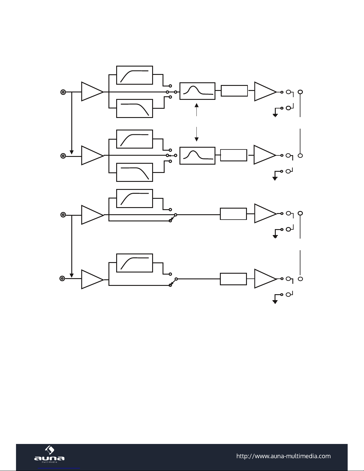
Circuit diagram
++++
----
++++
----
++++
----
3CH
HHC4C4
BTL
Normal
Inverted
Full
LEVEL
LOW BOOST
High-pass
Low-pass
LEVEL
LEVEL
High-pass
Full
Low-pass
Inverted
++++
----
++++
----
++++
----
2CH
1CH
BTL
LEVEL
4ch
3ch
2ch
Full
Normal
High-pass
BTLBTL
Hight-pass
1ch
Page 18

18
Input Connections
Right channel line output
Left channel line output
Car audio
Autoradio
To a metal of the car
Rear R/L channel line output
CH1
CH2
Front R/L channel line output
Car audio
Autoradio
POWER
CH 1
CH 2
SUPER BASS
X-OVER
6
12
HPF
FULL
LPF
50Hz
500Hz
HPF
50Hz250Hz
LPF
0
MIN
MAX
GAIN
CH1/CH2
AUDIO IN
Right channel line output
Left channel line output
Car audio
Autoradio
To a metal o f the car
CH 5
CH 6
CH 1
CH 2
CH3
CH4
X-OVER
SUPER BASS
6
12
HPF
FULL
LPF
50Hz 500Hz
50Hz250Hz
HPF LPF
0
MIN
MAX
GAIN
CH1/CH2
X-OVER
GAIN
X-OVER
MIN
FULL
HPF
MIN
MAX
GAIN
50Hz 500Hz
HPF
HPF
FULL
50Hz 500HzMAX
HPF
CH3/CH4 CH5/CH6
POWER
CH 1
CH 2
X-OVER
SUPER BASS
LPF 6
HPF
50Hz 500Hz
HPF LPF
FULL
12
0
50Hz 250Hz
MIN
MAX
GAIN
CH3/CH4
CH 3
CH 4
CH1 OUT
CH2 OUT
FULL
X-OVER
HPF
MIN
MAX
GAIN
50Hz 500Hz
HPF
CH1/CH2
With 3-speaker system
With 2,4,6-speaker systems
Page 19

19
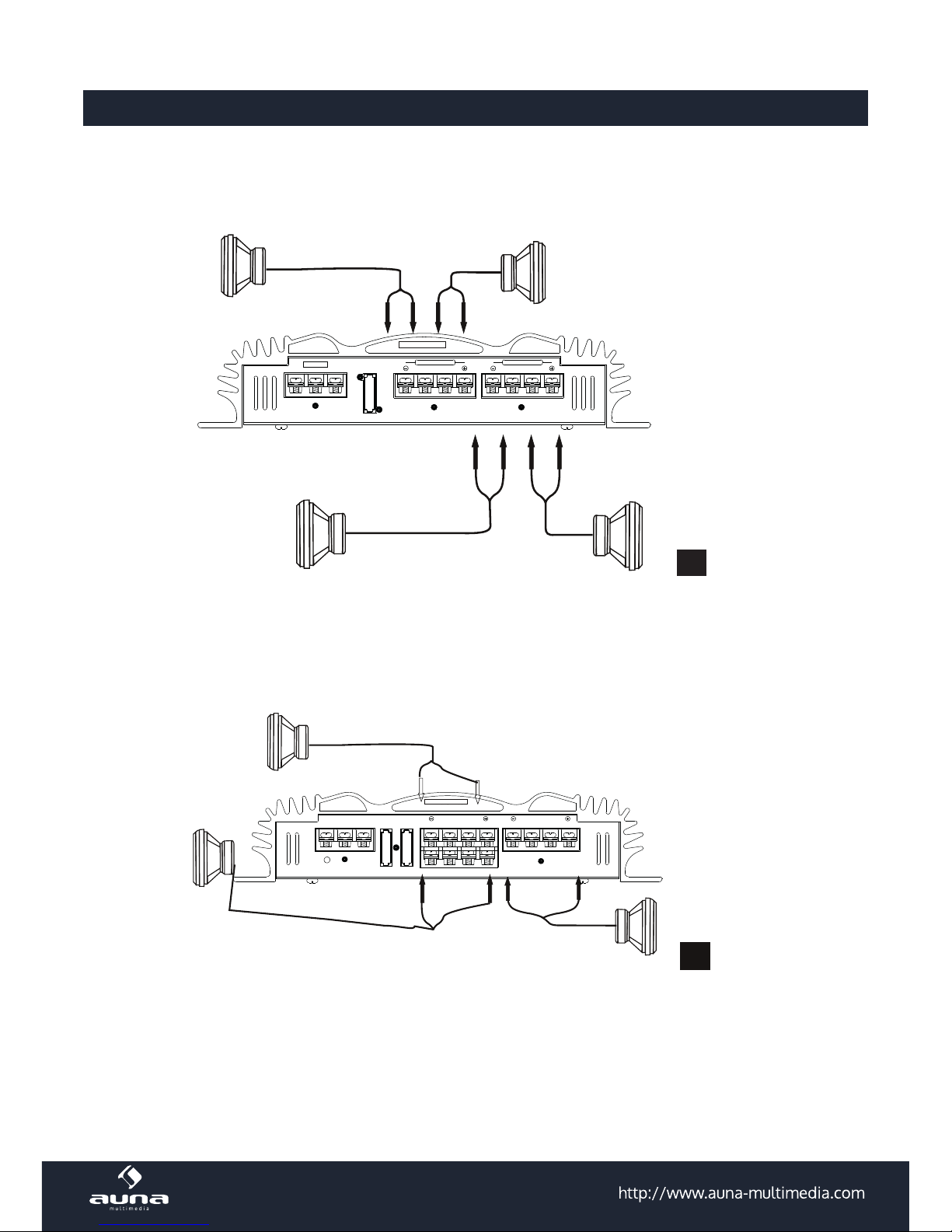
Speaker connections
CH4
CH1
CH2
speaker
(Min, 4 ohm)
speaker
(Min, 4 ohm)
speaker
(Min, 4 ohm)
speaker
(Min, 4 ohm)
C500.4
SPEAKER OUT
- CH3 +
- CH4 +
BRIDGE
GND
REMOTE
B+
FUSE
SPEAKER OUT
- CH1 +
- CH2 +
BRIDGE
(min, 4 ohm)
subwoofer speake
r
2
speaker
(Min, 4 ohm)
POWER
C500.6
- CH5 +
- CH6 +
- CH3 +
GND
REMOTE
B+
FUSE
SPEAKER
BRIDGE
- CH4 +
SPEAKER OUT
- CH1 +
- CH2 +
BRIDGE
4-speaker system
3-speaker system
1
Notes
in this system, the volume of the subwoofer will be controlled by the car audio fader control.
ln this system, the output signals to the subwoofer are a combination of both the REAR L and R INPUT
jack or the REAR high level input connector signals.
Page 20

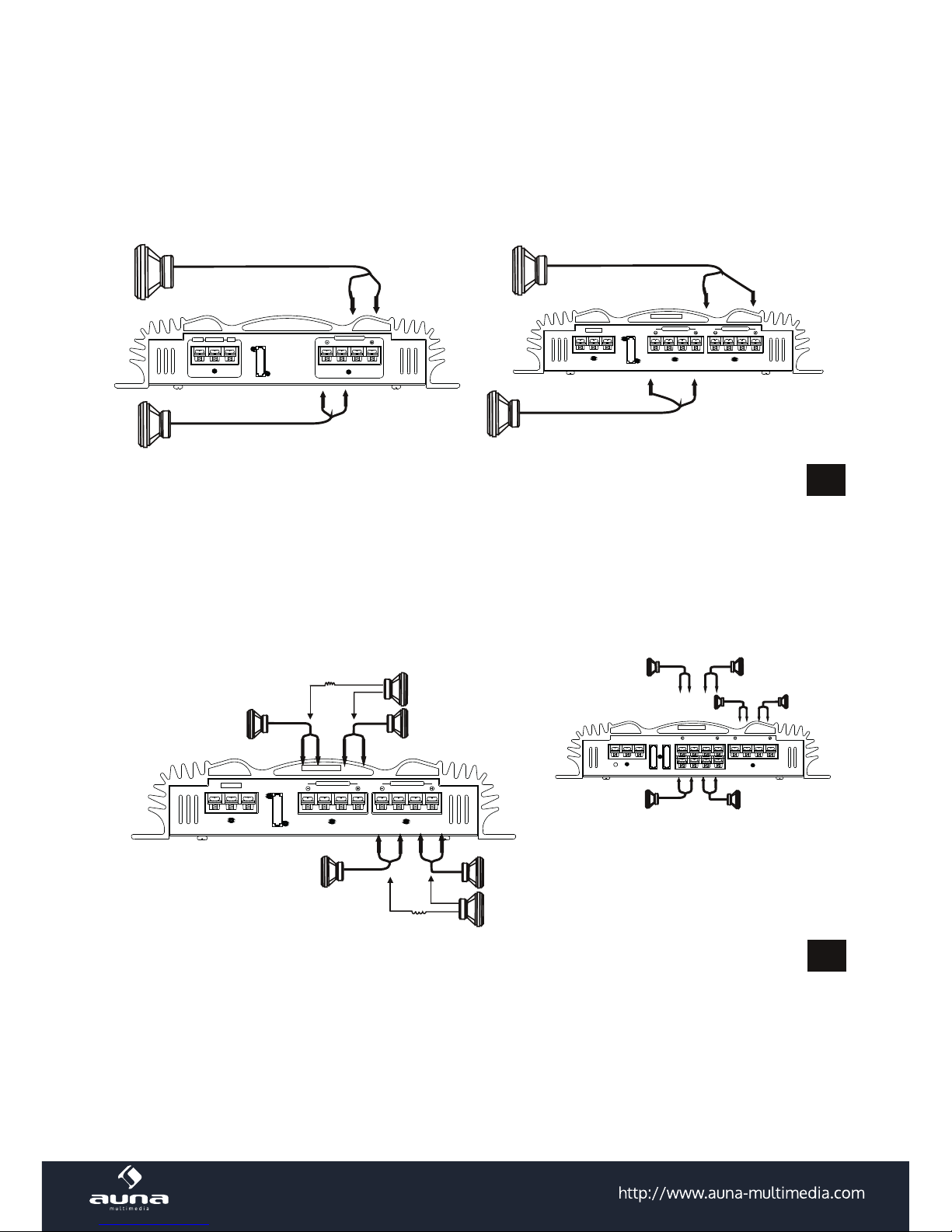
20
2-speaker system
For details on the settings of switches and controls, refer to "Location and function of controls.
6-speaker system
3
2-speaker system
For details on the settings of switches and controls, refer to "Location and function of controls."
SPEAKER OUT
- CH1 +
- CH2 +
BRIDGE
GND
REMOTE
B+
FUSE
Right speaker
(min. 4 ohm)
Left speaker
(min. 4 ohm)
Left speaker
(min. 4 ohm)
Right speaker
(min. 4 ohm)
GND
REMOTE
B+
FUSE
SPEAKER OUT
- CH1 +
- CH2 +
BRIDGE
SPEAKER OUT
- CH3 +
- CH4 +
BRIDGE
C500.4
3
2-speaker system
For details on the settings of switches and controls, refer to "Location and function of controls."
6-speaker
system
4
Subwoofer speakers
(min, 4 ohm)
Subwoofer speakers
(min, 4 ohm)
Full range speaker
(min, 4 ohm)
Full range speaker
Full range speaker
(min, 4 ohm)
Full range speaker
(min, 4 ohm)
(min, 4 ohm)
SPEAKER OUT
Note
in this system, the volume of subwoofers will be
controlled dy the car audio fader control
- CH1 +
- CH2 +
BRIDGE
GND
REMOTE
B+
FUSE
Right speaker
(min. 4 ohm)
Left speaker
(min. 4 ohm)
Left speaker
(min. 4 ohm)
Right speaker
(min. 4 ohm)
GND
REMOTE
B+
FUSE
SPEAKER OUT
- CH1 +
- CH2 +
BRIDGE
SPEAKER OUT
- CH3 +
- CH4 +
BRIDGE
C500.4
4
GND
REMOTE
B+
FUSE
SPEAKER OUT
- CH1 +
- CH2 +
BRIDGE
SPEAKER OUT
- CH3 +
- CH4 +
BRIDGE
C500.4
(min, 4 ohm)
Full range speaker
Full range speaker
Full range speaker
(min, 4 ohm)
(min, 4 ohm)
(min, 4 ohm)
Full range speaker
POWER
(min, 4 ohm)
Full range speaker
C500.6
- CH5 +
- CH6 +
- CH3 +
GND
REMOTE
B+
FUSE
SPEAKER
BRIDGE
- CH4 +
SPEAKER OUT
- CH1 +
- CH2 +
BRIDGE
Full range speaker
(min, 4 ohm)
Note: in this system, the volume of
subwoofers will be
controlled dy the car audio fader control.
Page 21

21
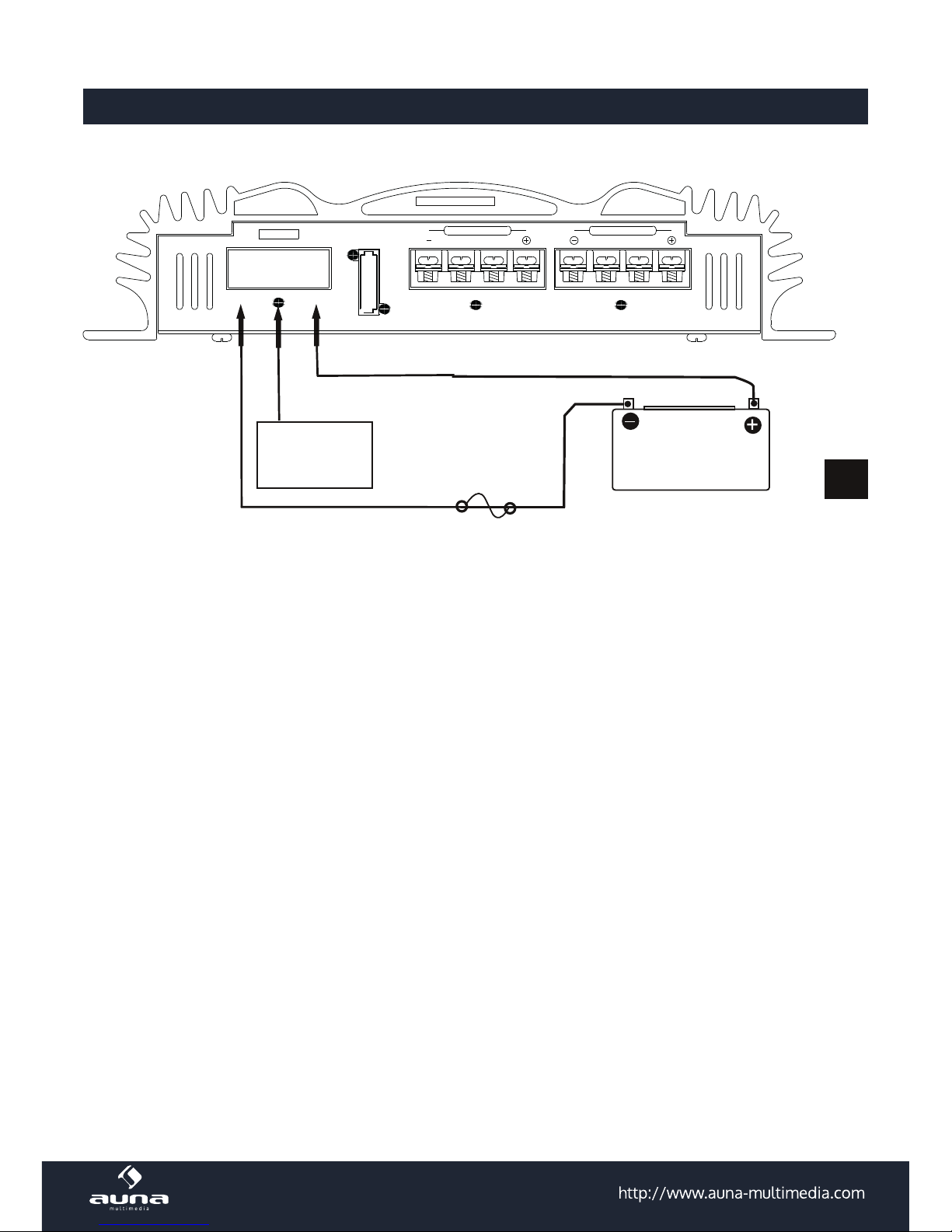
Power Connection Leads
Sortie be
Remote output*
Fuse
+12V
car battery
Car audio
Autoradio
5
GND
REMOTE
B+
FUSE
SPEAKER OUT
- CH1 +
- CH2 +
BRIDGE
SPEAKER OUT
- CH3 +
- CH4 +
BRIDGE
C500.4
Page 22

22
Installation
Before installation
• Mount the unit either inside the trunk or under a seat. Choose the mounting location carefully so the
unit will not interfere with the normal movements of the driver and it will not be exposed to direct
sunlight or hot air from the heater.
• Do not install the unit under the oor carpet, where the heat dissipation from the unit will be
considerably impaired.
Installation
First, place the unit where you plan to install it, and mark positions of the four screw holes on the
surface of the mounting board (not supplied), Then drill the hoes approximately 3 millimeters(mm) in
diameter and mount the unit onto the board with the supplied mounting screws.
The supplied mounting screws are 15mm long, Therefore, make sure that the mounting board is thicker
than 15mm.
Note: Tighten the screws rmly, but be careful not to apply too much force as doing so
may damage thee screws. the torque value should be less than 1 N m.
Page 23

23
CH 5
CH 6
CH 1
CH 2
CH3
CH4
POWER
POWER
C500.6
C500.4
C500.2
CH 1
CH 2
SUPER BASS
X-OVER
6
12
HPF
FULL
HPF
LPF
50Hz 500Hz
50Hz 250Hz
LPF
0
MIN
MAX
GAIN
CH1/CH2
AUDIO IN
CH 1
CH 2
6
12
HPF
FULL
LPF
50Hz 500Hz 50Hz 250Hz
X-OVER
SUPER BASS
HPF LPF
0
MIN MAX
GAIN
CH3/CH4
CH 3
CH 4
CH1 OUT
CH2 OUT
FULL
X-OVER
HPF
MIN MAX
GAIN
50Hz 500Hz
HPF
CH1/CH2
X-OVER
SUPER BASS
6
12
HPF
FULL
LPF
50Hz 500Hz
HPF
50Hz 250Hz
LPF
0
MIN MAX
GAIN
CH1/CH2
X-
OVER X-OVER
GAIN
MIN
FULL
HPF
MIN MAX
GAIN
50Hz 500Hz
HPF
HPF
FULL
50Hz 500Hz
MAX
HPF
CH3/CH4 CH5/CH6
Functioning
1. POWER indicator
Lights up in green during operation
2. PROTECTOR indicator
Lights up in red when output is powerful or in case of a speaker shortcut.
OVER CURRENT: Lights up in red when output is powerful or speaker shortcut.
3. FILTER selector switch
When the switch is in the LPF position the lter is set to low-pass. When in the HPF position, the
lter is set to high-pass.
4. Cut-o frequency adjustment control
Sets the cut-o frequency (50 Hz-250 Hz) for the low pass lter.
5. LOW BOOST level control
Turn this control to boost the frequencies around 50 Hz to a maximum of 12 dB,
6. LEVEL adjustment control
The input level can be adjusted with this control when using source equipment made by other
manufacturers.
7. Cut-o frequency adjustment control
Sets the cut-o frequency (50 Hz - 500 Hz) for the high pass lter.
Page 24

24
Troubleshooting
Problems Cause / Solution
The power indicator does not light up. • The fuse is loose or blown -- fasten the fuse or
change it with a new one.
• The ground lead is not securely connected -- fasten
a metal point of the car.
• The connection master unit is not turned on, -turn
on the master nuit.
• The system employs too many ampliers.--use a
relay.
• Check the battery voltage (10.5-15V).
The speaker output is o. The protection
indicator light up in red.
• The speaker outputs are short -circuited.-Turn o
power.
• switch, Rectify the cause of the short -circuit and
correct.
The unit heats up abnormally or
operating temperature.
• Use speakers with suitable impedance--2~8 Ω
(stereo), 4~8Ω (when used as a bridging amplier).
• Make sure to place the unit in a well ventilated
location.
Alternator noise is heard. • The power connecting leads are installed too close
to the RCA pin cords.--Tidy these connecting leads
and keep the leads away from the cords.
• The ground lead not securely connected--Fasten the
ground lead securely to a metal point of the car.
• Negative speaker leads are touching the car
chassis.--Keep the leads away from the car chassis.
The sound is muled. • The FILTER switch set to the "LPF" position.
The sound in too low. • The level adjustment control is set "MIN"position.
Page 25

25
Disposal Considerations
According to the European waste regulation 2012/19/EU this symbol on the
product or on its packaging indicates that this product may not be treated as
household waste. Instead it should be taken to the appropriate collection point
for the recycling of electrical and electronic equipment. By ensuring this product is
disposed of correctly, you will help prevent potential negative consequences for the
environment and human health, which could otherwise be caused by inappropriate
waste handling of this product. For more detailed information about recycling of this
product, please contact your local council or your household waste disposal service.
8
10R-041283
Page 26

26
Page 27

Page 28

 Loading...