

Page 1

4-Kanal-Mischpult
4-Channel Mixing Console
10034582 10034583
www.auna-multimedia.com
www.auna-multimedia.com
Page 2

DE
Sehr geehrter Kunde,
wir gratulieren Ihnen zum Erwerb Ihres Gerätes. Lesen Sie die folgenden Hinweise sorgfältig durch und befolgen Sie diese, um möglichen Schäden vorzubeugen. Für Schäden,
die durch Missachtung der Hinweise und unsachgemäßen Gebrauch entstehen, übernehmen wir keine Haftung.
SICHERHEITSHINWEISE
Magnetfeld
Vorsicht! Stellen Sie keine empfi ndlichen Hifi -Geräte wie Vorverstärker, Kassettendecks
direkt auf oder unter das Gerät. Da dieser Verstärker eine hohe Leistung hat, ensteht
ein starkes Magnetfeld, das bei nicht abgeschirmten Geräten in der Nähe ein Brummen
erzeugt. Das Feld ist über und unter dem Gerät am stärksten. Stellen Sie den Verstärker
in das unterste Regal und den Vorverstärker und andere empfi ndliche Geräte in die
oberen Regale.
Warnung: Gefahr eines Stromschlags. Gerät nicht öff nen.
Um einen elektrischen Stromschlag zu vermeiden, öff nen Sie nie das obere
oder untere Gehäuse. Wenden Sie sich an qualifi ziertes Fachpersonal. Ziehen
Sie das Netzkabel, bevor Sie die Rückwand entfernen, um an die Schalter zu
gelangen.
Setzen Sie dieses Gerät weder Regen noch Feuchtigkeit aus!
TECHNISCHE DATEN
EINGÄNGE:
Mikrofone ................................................................... 1,5 mV / 2 kΩ
Phono ......................................................................... 3 mV / 47 kΩ
Line-In .....................................................................150 mV / 27 kΩ
AUSGÄNGE:
Master .....................................................................0 dB / 1 V 600Ω
ALLGEMEIN:
Frequenzgang .................................................... 20Hz~20 KHz ±2 dB
Verzerrung..........................................................................<0,02 %
Signalrauschabstand ................................................. besser als 80 dB
Impedanz Kopfhörer ................................................................160 Ω
Stromanschluss ................................................230 V~ 50/60 Hz 5 W
2
Page 3
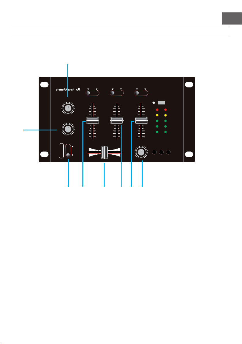
BEDIENFELDER UND ANSCHLÜSSE
AC 12V MIC2 MIC1
OUTPUT
AUX
CH2 CH1
R R R R
LLL L
PHONE
Vordere Armatur
1
PHONO PHONO STEREOLINE LINE MONO
DE
HEAD PHONE SMIC1 MIC2
MIC1 V OLUME
00 MAX
MIC2 V OLUME
CHAN NEL 1 CHAN NEL 2
MAX
MAX
MAX
2
00 MAX
TALK OV ER
00
ON OFF
CHAN NEL 1 CHAN NEL 2
00
3 4 5 6 7 8
1. MIC 1: Lautstärkeregler für den Anschluss MIC 1.
2. MIC 1: Lautstärkeregler für den Anschluss MIC 2.
3. Talkover: Übersprechdämpfung
4. Channel 1: Lautstärkeregler Kanal 1.
5. Crossfader: Kanal 1 und Kanal 2 überblenden.
6. Channel 2: Lautstärkeregler Kanal 2.
7. AUX: Lautstärkeregler AUX
8. PHONES: Lautstärkereglung Kopfhörer
ON POWE R
AUX
+5dB
+5dB
0dB
0dB
-5dB
OUTP UT METE R
CH1 CH2 AUX
-5dB
-10d B
-15d B
-10d B
-15d B
00
CUE
00
MAX
3
Page 4
DE
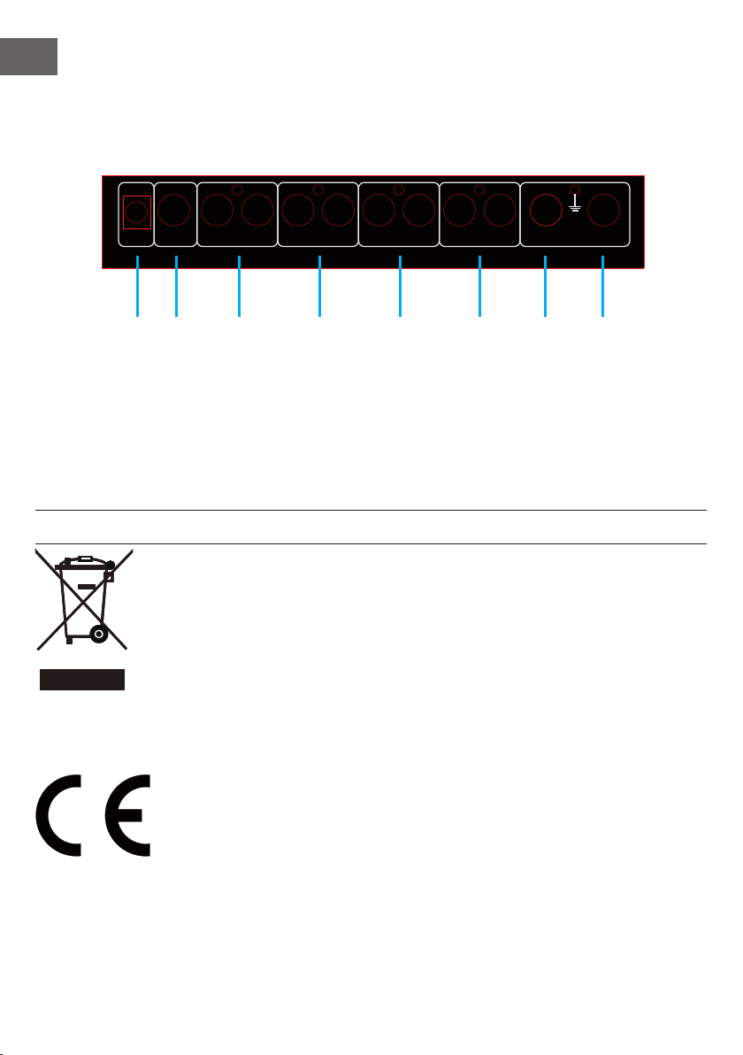
Anschlüsse Rückseite
LLL L
R R R R
PHONE
AC 12V MIC2 MIC1
OUTPUT
1 2 3 4 5 6 7 8
1. Netzteil-Anschluss
2. Kopfhörerausgang (¼")
3. Stereo-Line-Ausgang (Cinch)
4. Line-Input (Cinch)
ENTSORGUNG
Befi ndet sich die linke Abbildung (durchgestrichene Mülltonne auf Rädern)
auf dem Produkt, gilt die Europäische Richtlinie 2012/19/EU. Diese Produkte
dürfen nicht mit dem normalen Hausmüll entsorgt werden. Informieren Sie
sich über die örtlichen Regelungen zur getrennten Sammlung elektrischer
und elektronischer Gerätschaften. Richten Sie sich nach den örtlichen Regelungen und entsorgen Sie Altgeräte nicht über den Hausmüll. Durch die
regelkonforme Entsorgung der Altgeräte werden Umwelt und die Gesundheit
Ihrer Mitmenschen vor möglichen negativen Konsequenzen geschützt. Mate-
rialrecycling hilft, den Verbrauch von Rohstoff en zu verringern.
AUX
CH2 CH1
5. Eingang Kanal 2 (Cinch)
6. Eingang Kanal 2 (Cinch)
7. MIC 2 Eingang (¼")
8. MIC 1 Eingang (¼")
Konformitätserklärung
Hersteller: Chal-Tec GmbH, Wallstraße 16, 10179 Berlin,
Dieses Produkt entspricht den folgenden Europäischen Richtlinien
2014/30/EU (EMV)
2014/35/EU (Niederspannung)
2011/65/EU (RoHS)
4
Page 5

Dear Customer,
Congratulations on purchasing this equipment. Please read this manual carefully and
take care of the following hints on installation and use to avoid technical damages. Any
failure caused by ignoring the mentioned items and cautions mentioned in the operation
and installation instructions are not covered by our warranty and any liability.
SECURITY INSTRUCITONS
Magnetic fi eld
Caution! Do not locate sensitive high-gain equipment such as preamplifi ers or tape decks
directly above or below the unit. Because this amplifi er has a high power, it has a strong
magnetic fi eld which can induce hum into unshielded devices that are located nearby. The
fi eld is strongest just avoe and below the unit. Locate the amplifi er in the bottom of th
rack and the preamplifi er or other sensitive equipment at the top.
Warning: Risk of electric shock
Do not open!
To prevent electric shock do not remove top or bottom covers. No user
serviceable parts inside. Refer servicing to qualifi ed servicing personnel.
Disconnect power cord before removing back panel cover to access gain
switch.
Do not expose this equipment to rain or moisture!
EN
SPECIFICATIONS
INPUT:
DJ Mic ........................................................................ 1,5 mV / 2 kΩ
Phono ......................................................................... 3 mV / 47 kΩ
Line .........................................................................150 mV / 27 kΩ
OUTPUR:
Main ........................................................................0 dB / 1 V 600Ω
GENERAL:
Frequency response ............................................ 20Hz~20 KHz ±2 dB
Distortion ...........................................................................<0,02 %
S/N ratio ................................................................. besser als 80 dB
Headphone impedance .............................................................160 Ω
Power source ...................................................230 V~ 50/60 Hz 5 W
5
Page 6
EN
AC 12V MIC2 MIC1
OUTPUT
AUX
CH2 CH1
R R R R
LLL L
PHONE
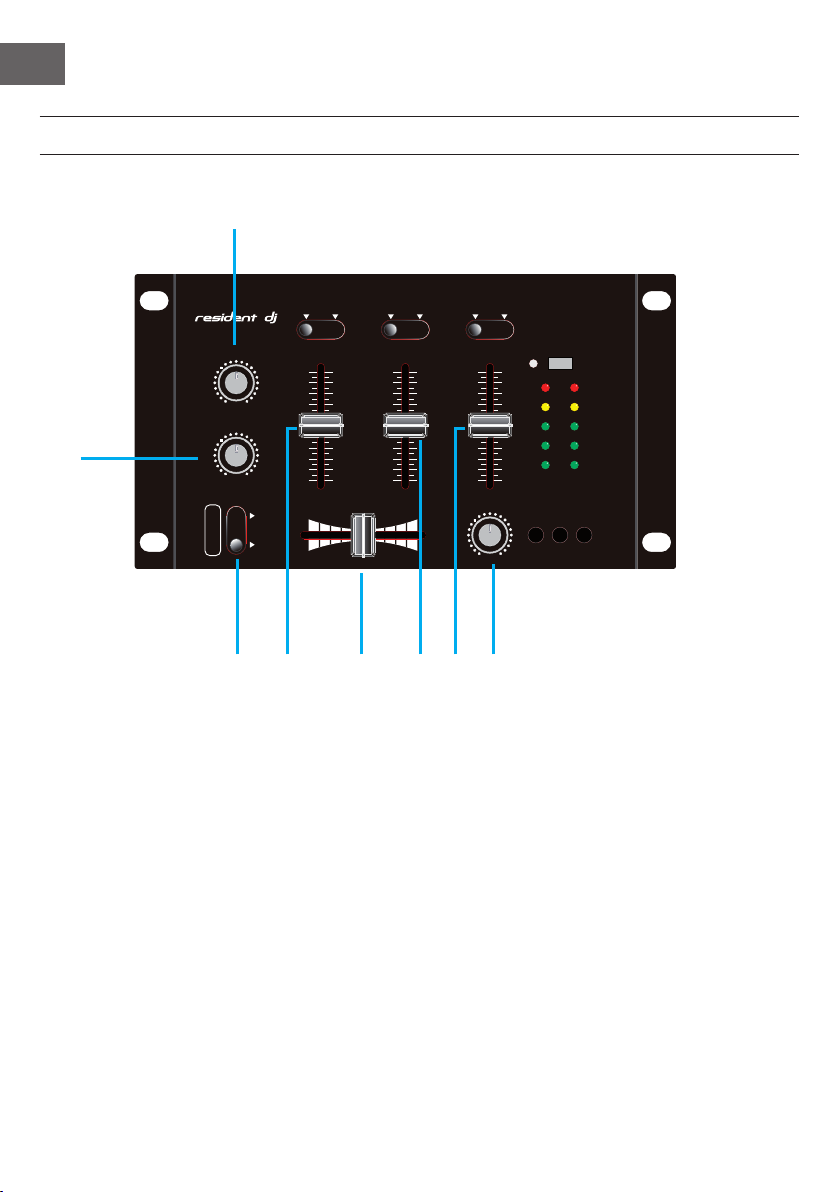
CONTROL PANEL AND CONNECTIONS
Front Panel
1
PHONO PHONO STEREOLINE LINE MONO
HEAD PHONE SMIC1 MIC2
MIC1 V OLUME
00 MAX
MIC2 V OLUME
CHAN NEL 1 CHAN NEL 2
MAX
MAX
MAX
2
00 MAX
TALK OV ER
00
ON OFF
CHAN NEL 1 CHAN NEL 2
00
00
00
3 4 5 6 7 8
1. MIC 1: potentiometer for MIC1 volume adjustment.
2. MIC 1: potentiometer for MIC1 volume adjustment.
3. Talkover: mute potentiometer control
4. Channel 1: dividing volume push rod.
5. Crossfader: signals volume push rod.
6. Channel 2: dividing volume push rod.
7. AUX: dividing volume push rod
8. PHONES: Phones volume control
AUX
CUE
-10d B
-15d B
MAX
ON POWE R
+5dB
0dB
-5dB
OUTP UT METE R
CH1 CH2 AUX
+5dB
0dB
-5dB
-10d B
-15d B
6
Page 7
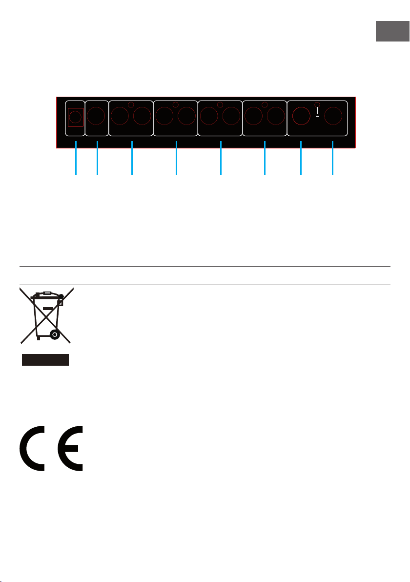
Backpanel Connections
LLL L
R R R R
EN
PHONE
AC 12V MIC2 MIC1
OUTPUT
AUX
1 2 3 4 5 6 7 8
1. AC connection
2. PHONE output (¼")
3. OUTPUT (RCA)
4. LINE Input (RCA)
DISPOSAL CONSIDERATIONS
According to the European waste regulation 2012/19/EU this symbol on the
product or on its packaging indicates that this product may not be treated
as household waste. Instead it should be taken to the appropriate collection
point for the recycling of electrical and electronic equipment. By ensuring
this product is disposed of correctly, you will help prevent potential negative
consequences for the environment and human health, which could otherwise
be caused by inappropriate waste handling of this product. For more detailed
information about recycling of this product, please contact your local council
or your household waste disposal service.
Declaration of Conformity
CH2 CH1
5. Channel 2 input (RCA)
6. Channel 1 input (RCA)
7. MIC 2 input (¼")
8. MIC 1 input (¼")
Producer: Chal-Tec GmbH, Wallstraße 16, 10179 Berlin. Germany
This product is conform to the following European Directives:
2014/30/EU (EMC)
2011/65/EU (RoHS)
2014/35/EU (LVD)
7
Page 8

 Loading...