

Page 1

http://www.auna-multimedia.com
Verstärker
10006684 10006685 10006686
10006687 10006688 10006689
2-Kanal Auto Endstufe
Page 2
2
Fehlerbehebung
Problem Lösung
Die Betriebsstatus-Anzeige leuchtet
nicht.
Sicherung lose oder defekt > Sicherung befestigen oder
ersetzen
Erdung nicht richtig befestigt > Erdung an Karosserie befestigen
Spannung am Remote-Anschluss zu gering, Radio nicht eingeschaltet > Radio einschalten
Zu viele Verstärker angeschlossen > Relais verwenden. Batterie prüfen (10.5-15V)
Ausgabe aus, Schutzleuchte leuchtet rot
Lautsprecherausgänge verursachen Kurzschluss > Ausschal-
ten, Kurzschluss nden und beheben
Lautsprecher mit der richtigen Impedanz verwenden > 2~8Ω
(Stereo), 4~8Ω (gebrückt)
Einbauort muss gut belüftet sein.
Störgeräusch hörbar Stromleitungen zu dicht an den Cinchkabeln verlegt > Leitun-
gen getrennt voneinander verlegen.
Erdung nicht richtig befestigt > Erdung an Karosserie befesti-
gen
Negative Lautsprecherleitung berührt die Karosserie > Halten
Sie die Lautsprecherleitungen fern von der Karosserie
Dumpfer Klang Filter auf LPF gestellt.
Ton zu leise Lautstärkeregler auf „MIN“ gestellt.
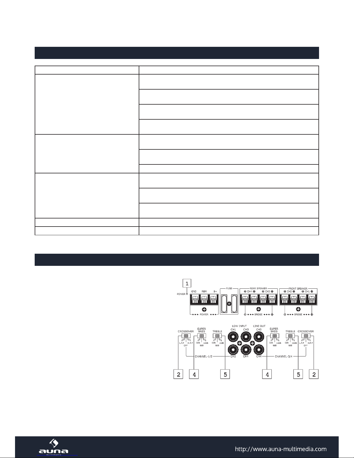
Anordnung der Bedienelemente
1. Betriebsstatus-Anzeige
Leuchtet rot während des Betriebs.
2. Filterwahlschalter
LPF - Niederbandlter
HPF - Hochbandlter
3. Frequenzregler
Frequenzabschnitt (50-250Hz)
für Niederbandlter
Page 3
3
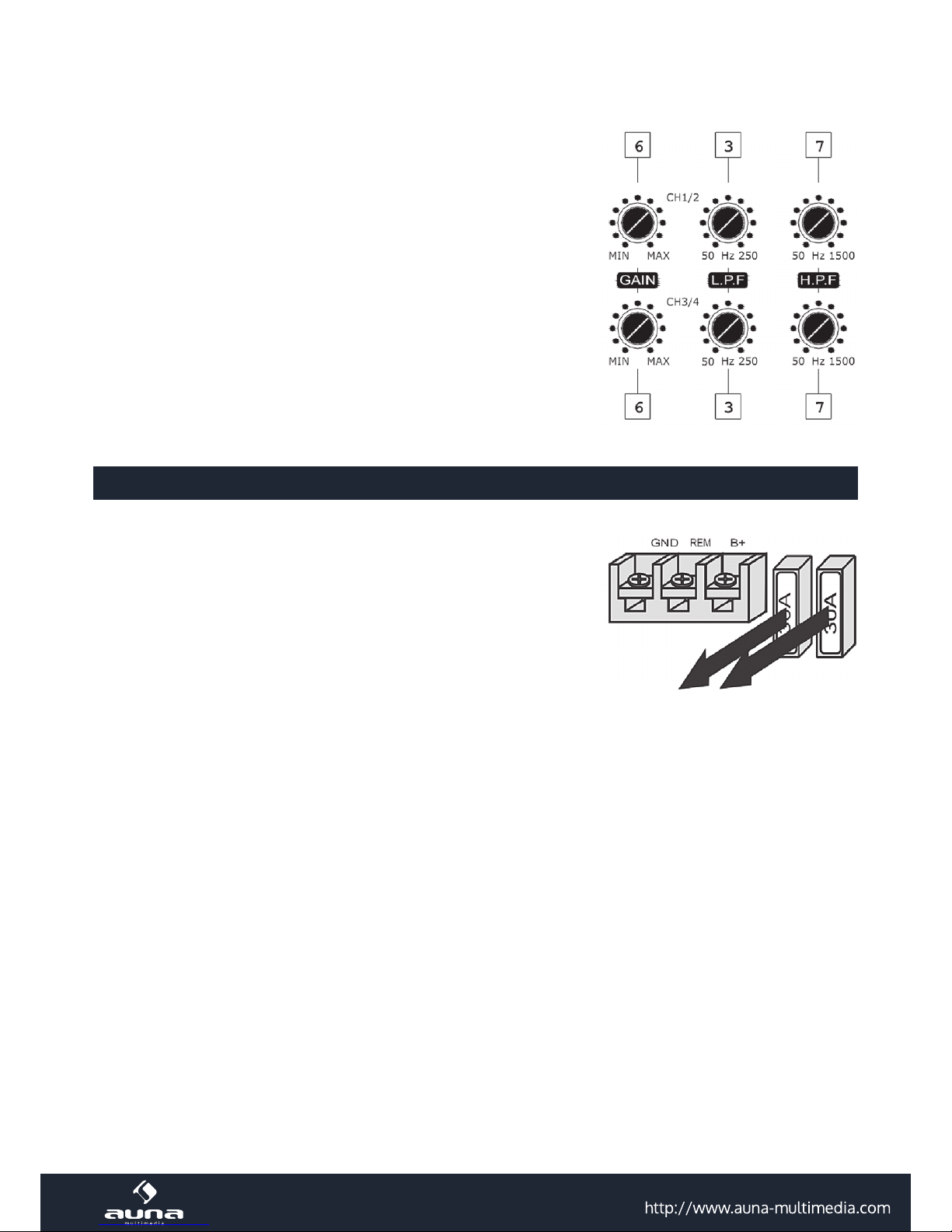
4. Bass-Boost-Regler
Verstärkt Frequenzen um 50Hz
bis maximal 12dB.
5. Höhen-Boost-Regler
Verstärkt Frequenzen um 10KHz bis maximal 12dB.
6. Lautstärkeregler
Regelt die Verstärkung. Kommt Ihnen die Lautstärke
zu gering vor, drehen Sie den Regler in Richtung MAX.
7. Frequenzregler
Frequenzabschnitt (50-250Hz) für Hochbandlter
Sicherung ersetzen
Ist die Sicherung defekt, prüfen Sie die Stromversorgung und
ersetzen Sie die Sicherung. Sollte die Sicherung erneut defekt
sein, liegt wahrscheinlich ein interner Defekt vor. Sie sollten sich
an den Händler wenden.
Warnung
Ersetzen Sie die Sicherung nur mit einer baugleichen Sicherung.
Verwenden Sie niemals eine Sicherung mit einem höheren Wert,
da sonst das Gerät Schaden nehmen kann.
Achtung
• Bevor Sie Bauteile anschließen, trennen Sie die Verbindung zum Minuspol der Batterie.
• Achten Sie darauf, dass die Lautsprecher über ausreichend Kapazität verfügen.
• Das negative Lautsprecherkabel darf nicht Karosserie berühren. Die negativen Lautsprecherkabel
des linken und rechten Lautsprechers dürfen auch nicht verwechselt werden.
• Verlegen Sie die Kabel für Signal und Stromversorgung voneinander entfernt, da es sonst zu
Störungen kommen kann.
• Dieser Hochleistungsverstärker kann seine volle Leistung nicht mit den serienmäßigen Laut sprecher entfalten.
• Sollten Sie ein Fahrzeug mit serienmäßiger Navigation besitzen, kann es sein, dass der interne
Speicher gelöscht wird, sobald Sie den Minuspol von der Batterie lösen.
Page 4
4
Gerät anschließen
Schließen Sie die Leitungen wie hier gezeigt an.
Notiz
Ziehen Sie die Schrauben fest, verwenden Sie
aber nicht zu viel Kraft*, da sonst die Schrauben beschädigt werden.
*Das Anzugsmoment sollte weniger als 1N•m betragen.c
Schaltplan
Halten Sie das Gerät zuerst an die Position
an der es eingebaut werden soll. Zeichnen
Sie die vier Punkte für Schraubenlöcher an.
Bohren Sie die Löcher mit ca. 3mm Durchmesser und befestigen Sie den Verstärker mit
den 15mm Schrauben. Vergewissern Sie sich,
dass die Montageplatte (nicht im Lieferumfang enthalten) dicker als 15mm ist.
Page 5

5
Eingangsanschlüsse
Line-Eingang (mit Lautsprecheranschluss 3)
Line-Eingang (mit Lautsprecheranschluss 1,2 oder 3)
5-Lautsprechersystem
Für die Bedienung siehe „Anordnung der Bedienelemente“.
Page 6

6
3-Lautsprechersystem
Für die Bedienung siehe „Anordnung der Bedienelemente“.
Notiz
Bei dieser Variante wird die Subwooferlautstärke mittels Fader-Einstellung des Autoradios eingestellt.
Die Ausgabesignale zum Subwoofer sind eine Kombination der ¾ Kanäle oder dem Basseingangssignal.
2-Lautsprechersystem
Für die Bedienung siehe „Anordnung der Bedienelemente“.
Stromversorgung
*Falls ein Radio ohne Remote-Ausgang verbaut ist, schließen Sie REMOTE an die Zubehörstromversorgung an.
Page 7

7
Notiz zur Stromversorgung
• Schließen Sie +12V erst an nachdem Sie alle anderen Verbindungen angeschlossen haben.
• Die Erdung muss sicher mit der Karosserie (Metall) verbunden sein, da es sonst zu Fehlern
kommen kann.
• REMOTE muss mit dem Remote-Ausgang am Radio verbunden sein.
• Falls ein Radio ohne Remote-Ausgang verbaut ist, schließen Sie REMOTE an die Zubehörstrom versorgung an.
• Verwenden Sie ein Stromkabel mit integrierter Sicherung (7.5A 2).
• Die Sicherung muss so nah wie möglich an der Batterie sein.
• Die +12V- und GND-Leitung müssen über einen Durchmesserwert von AWG-10 oder einen
Durchmesser von 5mm verfügen.
Vorsichtsmaßnahmen
• Das Gerät darf nur an 12V Gleichspannung betrieben werden.
• Die Lautsprecher müssen über eine ausreichende Impedanz 2~16Ω (Stereo) verfügen.
• Schließen Sie niemals Aktivlautsprecher an den Verstärker an.
• Bauen Sie den Verstärker nicht ein, wo:
- dieser direkten Sonnenlicht oder hohen Temperaturen ausgesetzt ist.
- dieser Regen oder Feuchtigkeit ausgesetzt ist.
- dieser Staub und Schmutz ausgesetzt ist. Sollte sich das Auto in der Sonne aufgeheizt haben,
lassen Sie es vor Gebrauch abkühlen.
• Sollte das Gerät horizontal verbaut werden, dürfen die Kühlrippen nicht vom Bodenteppich
verdeckt werden.
• Ist das Gerät zu nah am Radio verbaut, kann es dieses stören.
• Liegt kein Strom am Gerät an, prüfen Sie die Anschlüsse.
• Das Gerät verfügt über einen Schutzschaltkreis, der die Transistoren und Lautsprecher bei
Fehlfunktionen schützt.
• Versuchen Sie niemals diesen Schutzschaltkreis zu testen.
• Stellen Sie aus Sicherheitsgründen die Lautstärke immer so ein, dass Sie die Außengeräusche
noch hören können.
Schutzschaltkreis
Dieser Schaltkreis schützt das Gerät vor:
- Überhitzung.
- Überspannung.
- Kurzschluss
Die Sicherungslampe leuchtet dann rot auf und das Gerät schaltet sich ab. Ist dieses passiert, schalten Sie angeschlossenes Zubehör aus und suchen die Ursache. Sollte Überhitzung die Ursache sein,
lassen Sie das Gerät einige Zeit abkühlen.
Page 8

8
Einbau
Vor dem Einbau
• Das Gerät wird entweder unter einem Sitz oder im Koerraum
eingebaut.
• Befestigen Sie das Gerät so, dass der Fahrer nicht in seinen
Bewegungen eingeschränkt, das Gerät keinem direkten Sonnen licht oder Hitze ausgesetzt wird.
• Verbauen Sie das Gerät nicht unter dem Bodenteppich, da es
zu einem Hitzestau führen kann.
Sicherheitshinweise
• Reparaturen am Gerät sollten nur von einer autorisierten Fachwerkstatt durchgeführt werden.
• Önen Sie in keinem Fall das Gerät.
• Falscher Zusammenbau führt möglicherweise zu Fehlfunktionen oder dem Totalausfall.
• Das Gerät sollte vor jeglichen Feuchtigkeit und direkter Sonneneinstrahlung geschützt werden.
• Das Gerät bitte nicht mit Reinigungsmitteln reinigen.
• Verwenden Sie zur Reinigung nur ein trockenes (Mikrofaser) Tuch.
• Schließen Sie das Gerät nur an die dafür vorgesehene Netzspannung.
• Schließen Sie das Gerät in keinem Fall an andere Spannungen als vorgesehen an.
Die Gewährleistung verfällt bei Fremdeingrien in das Gerät.
Hinweise zur Entsorgung
Bendet sich die linke Abbildung (durchgestrichene Mülltonne auf Rädern) auf dem
Produkt, gilt die Europäische Richtlinie 2012/19/EU. Diese Produkte dürfen nicht mit
dem normalen Hausmüll entsorgt werden. Informieren Sie sich über die örtlichen
Regelungen zur getrennten Sammlung elektrischer und elektronischer Gerätschaften. Richten Sie sich nach den örtlichen Regelungen und entsorgen Sie Altgeräte
nicht über den Hausmüll. Durch die regelkonforme Entsorgung der Altgeräte werden
Umwelt und die Gesundheit ihrer Mitmenschen vor möglichen negativen Konsequen-
zen geschützt. Materialrecycling hilft, den Verbrauch von Rohstoen zu verringern.
8
10R-041283
Page 9

9
Troubleshooting Guide
Problem Cause / solution
The power indicator does not light up. • The fuse is loose or blown. -- Fasten the fuse or change it
with a new one.
• The ground lead is not securely connected. -- Fasten a
metal point of the car.
• The voltage going into zje remote terminal ist too low.
The connection master unit is not turned on. -- Turn on the
masternuit.
• The sytem employs too many ampliers. -- Use al Relay.
Check the battery voltage (10.5-15V)
Outout o, The protection indicator light
up in red.
• The speaker outpulse are short-circulated. -- Turn o power switch. Rectify the cause of the short-circuit and correct.
The unit heats up abnormaly or operating temperature.
• Use speakers with suitable impedance. -- 2~8Ω (stereo),
4~8Ω (when used as a bridging amplier)
• Make sure to place the unit in a well ventilated location
Alternator noise is heard. • The power connectingleads are installes too close to the
RCA pin cords. -- Tidy these connectingleads and keep the
leads away from the cords.
• The ground lead not securely connected. -- Fasten the
ground lead securely to al metal point of the car.
• Negative speaker leads ate touching the car chassis. -Keep the leads away from the car chassis.
The sound is mued. • The lter switch set to the „LPF“ position.
The sound in too low. • The level adjustment control is set „MIN“ position.
Location and function of controls
1. POWER indicator
Lights up in red during operation.
2. FILTER selector switch
When the switch is in the LPF position, the
lter is set to low-pass.
When in the HPF position, the lter is set to
high-pass.
3. Cut-o frequency adjustment control
Sets the cut-o frequency (50-250Hz)
for the low-pass lter.
Page 10

10
4. BASS BOOST level control
Turn this control to boost the frequencies around 50 Hz
to a maximum of 12 dB.
5. TREBLE BOOST level control
Turn this control to boost the frequencies around 10 KHz
to a maximum of 12 dB.
6. LEVEL adjustment control
The input level can be adjusted with this control when using
source equipment made by other manufacturers. Turn it to MAX
when the output level of the car audio seems low.
7. Cut-o frequency adjustment control
Sets zhe cut-o frequency (50-250Hz) for the high-pass lter.
Fuse replacement
If the fuse blows, check the power connection an replace the
fuse. If the fuse blows again after replacement, there may be an
internal malfunction. In such a case, consult your nearest goods
dealer.
Warning
When replacing the fuse, be sure to use one matching the am-
pler stated above the fuse holder. Never use a fuse with an
amperage rating exceeding the one supplied with the unit as this
could damage the unit.
Caution
• Befor making any connections, disconnect teh ground terminal of the car battery to avoid short
circuits.
• Be sure zo use speakers with an adequate power rating. If you use small capacity speakers, they
may be damage.
• Do not connect the „-“terminal of speaker system to the car chassis and do not connect the “-“
terminalof teh right speaker with that of the left speaker.
• Install the input and output cords away from the power supply lead as running them close together
can generate some interference noise.
• This unit is a high powered amplier. Therefore, it may not perform to its full potential if used with
the speaker cords supplied with the car.
• If your car is equipped with a computer system for navigation or some other purpose, do not
remove the ground wire from the car battery. If you disconnect the wire, computer memory mqay
be erased. To avoid short circuits when making connections, disconnect the +12V power supply lead
until all the other leads have been connected.
Page 11

11
Terminal Connections
Connections as illustrated below
Note
tighten the screws frimly, but be coreful not
to apply too much force* as doing so many
damage thee screws.
*the torque value shouold be less than 1N•m
Circuit diagram
First, place the unit where you plan to install
it, and mark postion of the four screw holes
on the surface of teh mounting board (not)
supplied). Then drill the hoes approximately 3
millimeters (mm) in diameter and mount the
unit onto the board with the supplied mounting screws are 15 mm long. Therefore, make
sure that the mounting board is thicker than
15 mm.
Page 12

12
Input Connections
Line input connection (with speaker connection 3)
Line input connection (with speaker connection 1, 2 or 3)
5-speaker system
For details on the settings of switches and controls, refer to“Location and functions of controls.“
Page 13

13
3-speaker system
For details on the settings of switches and controls, refer to“Location and functions of controls.“
Notes
In this system, the volume of the subwoofer will be controlled by the car audio fader contol. In this
system, the output signals to the subwoofer are a combination of both the ¾ channel jack or the BASS
high level input connector signals.
2-speaker system
For details on the settings of switches and controls, refer to“Location and functions of controls.“
Power connection leads
*if you have the factory original or some other car audio without a remove out-put on the ampilier, connect the remove input
terminal (REMOTE) to the accessory power supply.
Page 14

14
Notes on the power supply
• Connect the +12V power supply lead only after all the other leads have been connected.
• Be sure to connect the ground lead of the unit securely to a metal point of the car. A loose connection
may cause a malfunction of the amplier.
• Be sure to connect the remote control lead of the car audio to the remote terminal,
• When using a car audio without a remote output on the amplier, connect the remote input terminal
(REMOTE)to the accessory Power supply.
• Use the power supply lead with a fuse attached <7. 5A 2).
• Place the fuse in the power supply lead as close as possible to the car battery.
• Make sure that the leads to be connected to the +12Vand GND terminals of this unit are larger
than 10-Gauge (AWG-10) or have a sectional area of more than 5 (mm)
Precautions
• This unit is designed for negative ground 12V DCoperation only.
• Use speakers with suitable impedance.--2 to 16ohm (stereo).
• Do not connect any active speakers (with built~in amplier)to the speaker terminals of the nuit.
• Avoid installing the unit where:
- it would be subject to high temperatures such as from direct sunlight or hot airfrom the heater.
- it would be exposed to rain or moisture.
- it would be subject to dust or dirt. If your car is parked in direct sunlight and there is a considerable
rise in temperature inside the car, allow the unit to cool down before use.
• When installing the unit horizontally, be sure not to cover the ns with the floor carpet etc.
• If this unit is placed too close to the car radio, interference may occur. In this case, relocate the
amplier away from the car radio.
• If no power is being supplied to the master unit, check the connections.
• This power amplier employs a protection circuit to protect the transistors and speakers if the
amplier malfunctions.
• Do not attempt to test the protection circuit by covering the heat dink or connecting improperloads.
• Do not use the unit on a weak battery as its optimum performance depends on s good power supply.
•
For safety reasons, keep you caraudio volume moderate so that you can still hearsounds outside your car.
Protection circuit
This amplier is provided with a protection circuit that operates in the following cases:
- when the unit is overheated
- when a DC current is generated
- when the speaker terminals are short circuited.
The PROTECTOR indicator lights up in red and the unit will shut down.
If this happens, turn o the connected equipment, take out the cassette tape or disc, and determine
the cause of the malfunction, If the amplier has overheated, wait until the unit cools down beforeuse.
Installation
Before installation
• Mount the unit either inside the trunk or under a seat
• Choose the mounting location carefully so the unit will not
interfere with the normal movements of the driver and it will
not be exposed to direct sunlight or hot air from the heater.
• Do not install the unit under the floor carpet, where the heat
dissipation from the unit will be considerably impaired.
Page 15

15
Hints on Disposal
According to the European waste regulation 2012/19/EU this symbol on the product or on its packaging indicates that this product may not be treated as household
waste. Instead it should be taken to the appropriate collection point for the recycling
of electrical and electronic equipment. By ensuring this product is disposed of correctly, you will help prevent potential negative consequences for the environment
and human health, which could otherwise be caused by inappropriate waste handling of this product. For more detailed information about recycling of this product,
please contact your local council or your household waste disposal service.
8
10R-041283
Page 16

16
Résolution des problèmes
Problème Solution
Le témoin lumineux de marche ne
s’allume pas.
Le fusible est mal xé ou défectueux > Fixer le fusible ou le
remplacer.
La terre est mal xée > Fixer la terre à la carrosserie
La tension de la borne à distance est trop faible, la radio n’est
pas allumée > Allumer la radio.
Trop d’amplicateurs branchés en même temps > Utiliser des
relais. Vérier la batterie (10.5-15V)
Pas de son en sortie, le voyant de
protection s’allume en rouge
Les sorties d’enceinte provoquent un court-circuit > Éteindre,
repérer la raison du court-circuit et le résoudre
Utiliser des enceintes d’impédance appropriée > 2~8 Ω (sté-
réo), 4~8 Ω (ponté).
L’emplacement de montage doit être bien aéré.
Bruits parasites audibles Les ls électriques ont été installés trop proche des câbles RCA
> disposer les ls de manière bien séparée.
La terre est mal xée > Fixer la terre à la carrosserie
Les ls d’enceinte négatifs touchent la carrosserie > Maintenir
les ls d’enceinte éloignés de la carrosserie
Son sourd Le ltre est sur la position « LPF ».
Le son est trop faible Le bouton de volume est réglé sur « MIN ».
Disposition des éléments de commande
1. Voyant lumineux de marche
S’allume en rouge en cours de fonctionnement.
2. Bouton de sélection du ltre
LPF – Filtre passe-bas
HPF – Filtre passe-haut
3. Bouton de sélection de la fréquence
Plage de fréquences (50-250 Hz) pour ltre
passe-bas
Page 17

17
4. Bouton d’amplication des basses
Amplie les fréquences de 50 Hz jusqu’à un maximum de 12 dB.
5. Bouton d’amplication des aigus
Amplie les fréquences de 10 KHz jusqu’à un maximum de 12
dB.
6. Bouton de réglage du volume
Régule l’amplication. Si le volume paraît trop bas, tourner ce
bouton vers le marqueur MAX.
7. Bouton de sélection de la fréquence
Plage de fréquences (50-250 Hz) pour ltre passe-haut
Remplacement du fusible
Si le fusible est défectueux, vérier l’alimentation électrique et
remplacer le fusible. Si le fusible est de nouveau défectueux,
cela signie qu’il y a probablement un défaut interne. Dans ce
cas, contacter le revendeur.
Avertissement
Remplacer le fusible uniquement avec un fusible de même type.
Ne jamais utiliser un fusible de valeur supérieure, car cela pourrait endommager l’appareil.
Attention
• Avant de brancher les composants, débrancher le pôle moins de la batterie.
• Veiller à ce que les enceintes disposent d’une puissance susante.
• Les câbles négatifs d’enceinte ne doivent pas toucher la carrosserie. Les câbles négatifs d’en-
ceinte des enceintes de gauche et de droite ne doivent pas non plus être interchangés.
• Disposer le câble de signal et le câble d’alimentation à l’écart l’un de l’autre pour éviter tout dys-
fonctionnement.
• Cet amplicateur de haute puissance peut ne pas exprimer toute sa puissance avec des enceintes
standard.
• Si le véhicule est équipé d’un système de navigation standard, il se peut que les enceintes internes soient désactivées si le pôle moins est débranché.
Page 18

18
Branchement de l’appareil
Brancher les ls comme illustré ci-contre.
Remarque
Visser les vis sans les serrer à fond* pour ne
pas endommager les vis.
*La force de serrage doit être inférieure à 1 N•m.c
Plan électrique
Tenir d’abord l’appareil dans la position à laquelle il doit être installé. Marquer au crayon
les 4 points qui serviront à percer les trous.
Percer des trous d’un diamètre d’env. 3 mm
et xer l’amplicateur avec des vis de 15 mm.
S’assurer que l’épaisseur de la plaquette de
montage (non fourni à la livraison) est supérieure à 15 mm.
Page 19

19
Connecteurs d’entrée
Entrée Line (avec branchement d’enceinte 3)
Entrée Line (avec branchement d’enceinte 1, 2 ou 3)
Système à 5 enceintes
Pour le mode d’utilisation, cf. « Disposition des éléments de commande ».
Page 20

20
Système à 3 enceintes
Pour le mode d’utilisation, cf. « Disposition des éléments de commande ».
Remarque
Dans le cas de cette variante, le volume du caisson de basse est réglable au moyen du fader de l’autoradio. Les
signaux de sortie du caisson de basse sont une combinaison du ¾ des canaux ou du signal d’entrée des basses.
Système à 2 enceintes
Pour le mode d’utilisation, cf. « Disposition des éléments de commande ».
Alimentation électrique
*Si une radio est montée sans sortie remote, brancher REMOTE à l’alimentation électrique de l’accessoire.
Page 21

21
Remarque sur l’alimentation électrique
• Brancher le +12 V uniquement après avoir eectué tous les autres branchements.
• La terre doit être bien branchée à la carrosserie (métal, pour éviter tout dysfonctionnement.
• REMOTE doit être connecté à la sortie remote de la radio.
• Si une radio est montée sans sortie remote, brancher REMOTE à l’alimentation électrique de l’ac-
cessoire.
• Utiliser un câble électrique avec fusible intégré (7.5 A 2).
• Le fusible doit être aussi près que possible de la batterie.
• Les câbles +12V et GND doivent avoir une valeur de diamètre AWG-10 ou un diamètre de 5 mm.
Mesures de sécurité
• L’appareil doit fonctionner uniquement sur une tension continue de 12 V.
• Les enceintes doivent disposer d’une impédance susante de 2~16 Ω (stéréo).
• Ne jamais brancher d’enceinte active à cet amplicateur.
• Ne pas installer l’amplicateur à un endroit :
- exposé à la lumière directe du soleil ou à de hautes températures.
- exposé à la pluie ou à l’humidité.
- exposé à la poussière et à la saleté. Si la voiture est a chaué au soleil, la laisser refroidir avant
utilisation.
• Si l’appareil est installé à l’horizontale, les ailettes de refroidissement ne doivent pas être recou-
vertes par le tapis de sol.
• Si l’appareil est installé près de la radio, des perturbations sont susceptibles de se produire.
• Si l’appareil n’est pas alimenté en électricité, vérier les branchements.
• L’appareil est équipé d’un circuit de protection qui protège les transistors et les enceints en cas
de dysfonctionnement.
• Ne jamais essayer de tester ce circuit de protection.
• Pour des raisons de sécurité, toujours régler le volume de sorte à continuer d’entendre les bruits
extérieurs.
Circuit de protection
Ce circuit de protection protège l’appareil de
- De la surchaue.
- De la surtension.
- Des courts-circuits.
Le voyant de sécurité s’allume alors en rouge et l’appareil s’éteint. Si cela survient, éteindre les ac-
cessoires connectés et en rechercher la cause. Si la cause est la surchaue, laisser l’appareil refroidir
pendant un certain temps.
Page 22

22
Montage
Avant le montage
• L’appareil doit être installé soit sous un siège soit dans le
core.
• Fixer l’appareil de sorte à ce qu’il n’entrave pas les mouvements du conducteur, à ce qu’il ne soit pas exposé à la lumière
du soleil ou à la chaleur.
• Ne pas installer l’appareil sous un tapis de sol, car cela pourrait provoquer une accumulation de chaleur.
Consignes de sécurité
• Seul un atelier spécialisé autorisé est habilité à eectuer des réparations sur l’appareil.
• Ne jamais ouvrir le boîtier de l’appareil.
• Un mauvais assemblage est susceptible de provoquer des dysfonctionnements ou une panne.
• Protéger l’appareil de l’humidité et de la lumière directe du soleil.
• Utiliser uniquement un chion sec (à microbres) pour nettoyer l’appareil.
• Brancher l’appareil uniquement à une tension d’alimentation adaptée.
• Ne jamais brancher l’appareil à une autre tension d’alimentation que celle prévue.
• La garantie s’annule en cas d’intervention extérieure sur l’appareil.
Information sur le recyclage
Vous trouverez sur le produit l’image ci-contre (une poubelle sur roues, barrée d'une
croix), ce qui indique que le produit se trouve soumis à la directive européenne
2012/19/UE. Renseignez-vous sur les dispositions en vigueur dans votre région
concernant la collecte séparée des appareils électriques et électroniques. Respectez-les et ne jetez pas les appareils usagés avec les ordures ménagères. La mise au
rebut correcte du produit usagé permet de préserver l’environnement et la santé.
Le recyclage des matériaux contribue à la préservation des ressources naturelles.
8
10R-041283
 Loading...