


Assembly and Commissioning
Instructions
according to Machinery Directive 2006 / 42 / EC (annex VI)
FVM2 - LOCKING DRIVE MINI FOR WINDOWS

CONTENTS
Abbreviations
Target Groups
Warning and Safety Symbols
Intended Use
01
Safety Instructions
Data sheet FVM2
Data sheet FVM2 with speci c application
Explanations on the product label
02
Determination of locking points
3 - 8
9 - 11
03
04
05
06
NSTALLATION STEP 1: Inspection before the installation
I
I
NSTALLATION STEP 2: Installation prerequisite and Installation preparation
I
NSTALLATION STEP 3A: Hole layouts (Application examples)
I
NSTALLATION STEP 3B: Hole layouts for locking drive FVM2
I
NSTALLATION STEP 3C: Milling layouts for concealed mounting inside pro les
I
NSTALLATION STEP 4: DIP switches setting (moving direction and the locking stroke)
I
NSTALLATION STEP 5: Assembly the locking drive
I
NSTALLATION STEP 6: Manual unlocking mechanism
12
13 - 14
15 - 17
17 - 23
NSTALLATION STEP 7: Electric Connection
I
I
NSTALLATION STEP 8: Supply lines of the Control Unit to the drives
I
NSTALLATION STEP 9: Safety check and Test run
Troubleshooting, Service and Repair
07
Maintenance and Modi cation
Removal and Disposal
Liability
Warranty and After-Sales Service
08
Assembly Instruction
2
FVM2
24 - 28
29

PRELIMINARY REMARK
ABBREVIATIONS
Index of abbreviations
These abbreviations are used consistently throughout these assembly
& operating instructions. Unless stated differently, all dimensions indicated in this document are in mm. General tolerances in accordance
with DIN ISO 2768-m.
A drive
AK connection cable / drive cable
AP cover cap
BD hinge
Fxxx casement bracket
FAB overall width of casement
FAH overall height of casement
FG casement weight
FL casement
FÜ casement overlap
HSK main closing edge
Kxxx frame bracket
L construction lenghth of drive
MB central hinge
NSK side closing edge
RA frame
RAB overall width of frame
RAH overall height of frame
SL snow load
opening direction
WARNING AND SAFETY SYMBOLS IN THESE IN-
STRUCTIONS:
The symbols used in the instructions shall be strictly observed and have
the following meaning:
!
DANGER
!
WARNING
!
CAUTION
NOTE
Failure to comply with the warning notes results
in irreversible injuries or death.
Failure to comply with the warning notes can result in irreversible injuries or death.
Failure to comply with the warning notes can result in minor or moderate (reversible) injuries.
Failure to comply with the warning notes can lead
to damage to property.
Caution / Warning
Danger due to electric current.
Caution / Warning
Risk of crushing and entrapment during device operation (is provided as a sticker with the drive).
01
RA
FL
HSK
NSK
BD
FAB
RAB
NSK
FA H
RAH
TARGET GROUP
These instructions are intended for trained personnel
and operators of systems for natural smoke ventilation
(NRA / SHEV) (natural smoke exhaust system / smoke and
heat exhaust system) and natural ventilation via windows,
who are knowledgeable of operating modes as well as the
remaining risks of the system.
Attention / Warning
Risk of damage to / destruction of drives and / or
!
!
WARNING
windows.
Once the assembly and commissioning
has been completed, the installer of a
machine „power-operated window and door“ shall hand
these instructions over to the end-user. The end-user shall
store these instructions in a safe place for further reference
and use, if required.
!
WARNING
This device is not intended for use by per-
sons (including children) with physical,
sensory or mental limitations or lacking experience and / or
knowledge, unless they are supervised by a person who is
responsible for the safety or were instructed by him on the
usage of this equipment. Children should be supervised to
ensure that they are not playing with this device.
Cleaning and operator’s maintenance may not be performed by children without supervision.
Assembly Instruction
FVM2
3

INTENDED USE
Area of application / Scope of application
This drive is intended for the electromotive locking and
unlocking of windows in facade and roof areas.
The main task of this product, in combination with
a window and a suitable external control unit, is to
01
evacuate hot smoke and combustion gases in case
of re, to safe human lives and protect material
assets. Furthermore, with the electromotive operated
window and a suitable external control unit, the natural
ventilation of the building can be ensured.
By attaching a drive to a movable
element of the window a so-called
“power-operated window” is created
NOTE
Intended use according
The drive is intended for stationary installation and
electrical connection at the window as part of a building.
The drive is in combination with an external Control Unit
(e.g. from A
power-operated window for the following use:
• Application for natural ventilation
with an installation height of the drive and
the bottom side of sash of at least 2,5 m above
the oor, or
with an opening width at the HSK of the driven
part of < 200 mm by a simultaneous speed of
< 15 mm/s at the HSK in closing direction.
• Application as NSHEV (natural smoke and heat
exhaust ventilator(s) for ventilation without dual
purpose for ventilation in accordance with EN12101-2.
which, according to the Machinery
Directive 2006 / 42 / EG, represents a
machine.
UMÜLLER) released for its proper use at a
PRELIMINARY REMARK
We as manufacturers are well aware of our duties and
responsibilities regarding the development, manufacturing and placing of safe window drives on the market and
consistently implement them. Ultimately, however, we have
no direct in uence on the usage of our drives. Therefore,
as a precaution, we point out the following:
• The constructor or his agent (architect, specialist
planner) are obligated to evaluate the
hazards to persons, outgoing from the usage,
installation position, opening parameters and from the
external Control Unit of the power operated window,
already in the planning phase and to establish
necessary protective measures.
• The constructor / manufacturer of the machine
“power-operated window” must implement the
planned protective measures at the installation-site
or, if not yet established, determine them by it´s
own responsibility and detect or minimize possible
remaining risks.
The need for a risk assessment at the installation-site
due to the reasonably foreseeable misuse.
A risk assessment in accordance with the Machinery
Directive 2006 / 42 / EG for the usage of the power-
operated window for natural ventilation is absolutely
necessary under the following conditions:
• the installation height of the drive and lower edge
of casement < 2,5 m above the oor
and one of the following conditions:
• the opening width at the HSK > 200 mm, or
• the closing speed at the HSK is > 15 mm/s, or
• the opening speed at the HSK is > 50 mm/s, or
• the closing force at the HSK is > 150 N
The manufacturer of the power-operated window has
to carry out a risk assessment for all other applications
independently - at the installation-site of the window.
Pay attention to possible hazards on
tilting or rotating windows, whose
secondary closing edges are located
!
WARNING
at less than 2,5 m installation height
above the oor, under consideration of
the Control Unit and usage!
Assembly Instruction
4
FVM2
The following ow chart can be applied, which also includes
the protective measures in accordance with EN 60335-2103/2016-05.

PRELIMINARY REMARK
Hazard analysis according to DIN EN 60335-2-103
NSHEV according to
EN12101-2 without
dual purpose for ventilation
CAUTION
!
Keep people away during closing!
CAUTION
!
Observe danger at NSK
< 2,5 m above oor!
Environment with children /
vulnerable people
Use of the drive
Natural ventilation
Installation height of drive and lower
edge of casement: > 2,5 m above oor
(ZAA.20.2)
No
Opening at HSK: < 200 mm and
Speed at HSK:
CLOSE <15 mm/s / OPEN < 50 mm/s
(20.ZAA.2)
No
CAUTION
!
Protection devices
Yes
Yes
NSHEV according to
EN12101-2 with
dual purpose for ventilation
(1.Z.109)
No
risc assessment
required
Risk analysis according to the
Machinery Directive required
01
Hold-to-run switch:
stops movement at HSK < 20 mm
at a closing force of > 150 N at HSK
(20.ZAA.5)
Operating element in
direct range of vision:
a.) Key switch or
b.) other switch,
then: installation > 1,5 m,
inaccessible for public
(7.12.1)
CAUTION
!
Keep people away during closing!
Contact-free anti-trap protection
(20.ZAA.8.1)
Passive infra-red and active light sensors
pressure mats
The information in the brackets
refer to the chapters of DIN EN 60335-2-103.
Casement data
Facade: bottom-hung window, top-hung-win dow, side-hung window.
Roof: roof window / sky light.
Opening direction: inward opening, outward opening.
Pro le material: aluminum, steel, plastic or wood.
Contact-based anti-trap protection
(20.ZAA.8.2)
Pressure-sensitive safety switch strips
or
Motor current monitoring systems
(internal and external)
Declaration of Conformity
power operated window
or
+ CE label
When inspecting the drives for conformity with on-site
requirements the following items must be observed:
• total weight of casement (glass + frame),
• casement size (FAB x FAH),
• driving force and stroke,
• mounting site at the window frame and casement
frame.
Assembly Instruction
FVM2
5

SAFETY INSTRUCTIONS
It is important to follow these instruc-
!
WARNING
01
Area of application
The drive shall only be used according to its intended use.
For additional applications consult the manufacturer or his
authorized dealer.
!
WARNING
Always check whether the system complies with current
legal regulations. Special attention must be paid to the
opening width, the opening area, the opening time and the
opening speed of the window, the temperature range of
the drives / external devices and cables as well as the cross
section of the connecting cables as function of the cable
length and power consumption.
!
tions for the safety of persons. These
instructions shall be kept in a safe place
for the entire service life of the products.
Risk of crushing and entrapment!
Window can close automatically!
The integrated load cut-off stops the
opening-drive during closing and opening
when the drive is overloaded.
The compressive force is absolutely
suf cient to crush ngers in case of
carelessness.
Do not misuse the drive for other
applications! Do not allow children to
play with this drive or its regulating
and / or control units, including the
remote control!
All devices must be permanently protected
from dirt and moisture, if the drive is not
explicitly suitable for use in wet areas (see
technical data).
SAFETY INSTRUCTIONS
Installation
These instructions address expert and safety-conscious
electricians and / or quali ed personnel knowledgeable in
electrical and mechanical drive installation.
All speci cations for installation must be checked independently and, if necessary, adjusted at the installation-site.
The connection assignment, the electrical supply data (see
machine plate) and performance limits (see technical data)
as well as the mounting and installation instructions of the
drive must be strictly observed and adhered to!
Do not reach into the window rabbet or the operating
element (chain or spindle) during installation and operation! Ensure that, based on the installation position and
the opening movement of the casement, persons cannot
be trapped between the driven part of the window and
surrounding xed components (e.g. wall).
Mounting material
The required mounting material must to t with the drive
and occurring load and, if necessary, supplemented.
NOTE
NOTE
The safe operation, avoidance of injury to
persons and damage to property, as well
as risks, is only guaranteed by proper
installation and setting according to
these installation instructions.
Never connect 24 V DC drives to 230 V AC
mains voltage!
Danger to life!
Before installing the drive, check whether
the casement is in good mechanical condition, the weight in balance and whether
it opens and closes easily!
Danger spots by crush and shear points
Side-hung Bottom-hung Roof windows / skyskylight domes Louvre windows
Danger spots: crush and shear points according to DIN EN 60335-2-103
Assembly Instruction
6
FVM2

SAFETY INSTRUCTIONS
Crush and shear points
To avoid injuries, crushing and shear points between
casement and frame must be secured against entrapment
up to an installation height of 2,5 meters above the
oor with appropriate measures. This can be achieved e.g.
by using contact-based or contactless protective devices
against entrapment, which stop the motion through contact or through interruption by a person. At a force higher
than 150 N at the main closing edge the motion must stop
within 20 mm. A warning symbol at the opening element
must indicate this clearly.
Unintentional or independent opening or falling
Casements are to be hinged or secured such way that in
case one of the mounting elements fails it will not crash /
slam down or move in an uncontrolled manner by e.g. using
double suspensions, safety scissors, casement stays.
Tilting windows shall be equipped with safety scissors or
similar devices to avoid damages and risks of injury for
persons through improper installation and operation. The
safety scissors must be adjusted to the opening stroke of
the drive (see technical data) to avoid blocking. The opening
width of the safety scissors must be bigger than the drive
stroke.
The movable casement must be secured
!
WARNING
against unintentional or independent
opening as well as falling down.
safety scissors
All-pole disconnecting devices shall be installed in the permanent electrical installation or
external Control Unit for the drive.
The mains supply lines 230 V / 400 V AC shall
be protected separately!
24V DC drives may only be connected to
power supply sources that comply with SELV
speci cations.
In the case of tandem / multiple operation of drives connected in series, the
cross-section of the connection cable
NOTE
!
WARNING
The types of cable, cable lengths and cross-sections shall
be selected in accordance with the manufacturer’s technical
data. If necessary, the cable types shall be coordinated with
the competent local authorities and energy supply companies. Low-voltage lines (24 V DC) shall be routed
separate from the high-voltage lines. Flexible cables may
not be ush-mounted. Freely suspended cables shall be
equipped with strain reliefs.
must be checked autonomously, depending on the total current consumption of
the drive system.
Damaged mains supply lines of drives
with plug connectors may only be replaced by the manufacturer or quali ed
service / maintenance personnel!
Power cables which are xed to the drive
casing cannot be replaced. If the cable is
damaged the device must be scrapped!
0101
Routing cables and electrical connection
Routing or installing of electrical cables and connections
may be performed only by specialist companies. Never
operate drives, control units, operating elements and
sensorsat operating voltages and connections contrary
to the speci cations of the manufacturer.
All relevant instructions shall be observed for the installation, speci cally:
• VDE 0100 Setting up high-voltage systems up to 1000 V
• VDE 0815 Wiring cables
• Specimen Guideline on Conduits German designation
(MLAR).
Cables must be laid such way that they cannot be sheared off, twisted or bent during
operation. Drive cables laid inside window
pro les must be protected by insulating
tubes with a suf cient temperature resistance.
Through holes shall be equipped with cable
sleeves!
Clamping points shall be checked for tightness of threaded connections and cable ends. Access to junction boxes,
clamping points and external drive control boxes shall be
ensured for maintenance work.
Assembly Instruction
FVM2
7

SAFETY INSTRUCTIONS
Commissioning, operation and maintenance
After the installation and after each modi cation in the set
up all functions shall be checked with a trial run. It shall
be ensured that drive and casement are set correctly and
01
that security systems, if available, are functioning properly.
After the installation of the system is completed the
end-user shall be introduced to all important operating steps. If necessary, he must be advised of all remaining
risks / dangers.
The end-user shall be speci cally instructed that no
additional forces, except pushing and pulling forces in the
opening and closing direction of the casement, may be
applied to the spindle, chain or lever of the drive.
NOTE
During cleaning and maintenance works and while
exchanging parts, all poles of the drive must be disconnected from the power supplyand and secured
against unintentional reactivation.
!
CAUTION
!
CAUTION
!
CAUTION
Post warning signs!
Other persons must be kept away from
the casement when a hold-to-run switch
(push button) is operated or when a
window, which has been opened by a
smoke and heat exhaust system, is closing!
The operating element of hold-to-run
switches must be installed within direct view from the window, but apart
from moving elements. If the switch is
not a key-operated switch it must be
installed at a minimum height of 1,5 m
and inaccessible to the public!
Do not allow children to play with
permanently mounted control devices
and keep remote controls out of reach
for children!
Replacement parts, fasteners and controls
The drive shall only be operated with control devices from
the same manufacturer. There is no liability, warranty or
customer service if third-party parts are used. Exclusively
original replacement parts of the manufacturer shall be
used for mounting elements or expansions.
Ambient conditions
The product may not be subjected to impacts or falls, or
to vibrations, moisture, aggressive vapors or other harmful
environments, unless the manufacturer released it for one
or more of these environmental conditions.
• Operation:
Ambient temperature: -5 °C … +60°C
Relative humidity: < 90% less 20°C;
< 50% less 40°C;
no formation of condensation
Observe temperature range during
NOTE
installation!
• Transport / Storage:
Storage temperature: -5°C … +40°C
Relative humidity: < 60%
Accident prevention regulations and workmen’s
compensation insurance guidelines
For work on or in a building or building part the provisions and instructions of the respective accident prevention
regulations (local workmen’s compensation insurance
guidelines) shall be observed and adhered to.
Declaration of Conformity and of Incorporation
The drive is manufactured and inspected in accordance with
European guidelines. The respective Declaration of Conformity and of Incorporation is on hand.
In case that the use of the drive differs from the intended use, a risk evaluation for the power operated
window shall be performed and a Declaration of Conformity according Machinery Directive 2006 / 42 / EG
issued.
During cleaning, maintenance work and while
exchanging parts the drive must be completely disconnected from the power supply and
secured against unintentional reactivation.
Do not actuate the drive or the case-
!
WARNING
Assembly Instruction
8
ment when repair or re-setting works are
performed!
FVM2

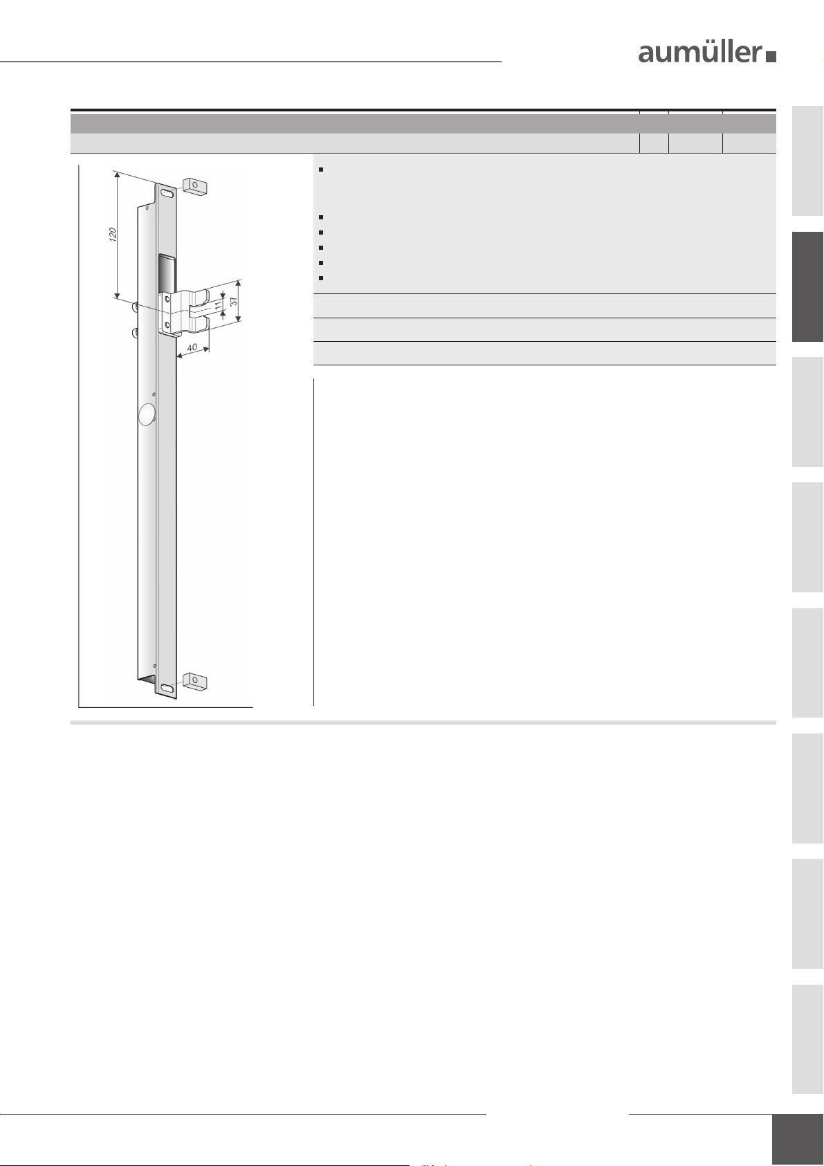
DATA SHEET FVM2
25
10
5,5
7
max. 113
11
2 x 17 ±1
205
s=36 ±2
34
30
12,5
473
DATA SHEET
Application: natural ventilation, SHEV, ferralux®-NSHEV
Surface or concealed mounting inside pro les
Locking plate (8 mm) on top or bottom mountable
Locking position selectable: right / left
Locking stroke selectable: s = 36 mm or 17 mm
Manual unlocking mechanism
Options
Special functions programmable
M-COM suitable internal Control Electronics and sequence control for drives S3 /S12
Star wiring
37
Current of the drives does not run over FVM2
Sequence control via communication wire
TECHNICAL DATA
U
Rated voltage 24V DC (19 V ... 28 V)
N
Cut-off current ~ 0,4 A
I
A
P
Rated power 10 W
N
Current of opening drives non relevant
ID
DC Duty cycle 5 cycles (ED 30 % - ON: 3 min. / OFF: 7 min.)
Protection rating IP 32
02
7
ACCESSORIES
Hardware set
B23
Ambient temperature range -5 °C ... +60 °C
F
Pushing / Pulling force max. ~ 600 N
A
F
Breaking fore max. ~ 1000 N
L
t Housing / Locking plate stainless steel
Connecting cable non-halogen, grey 3 x 0,5 mm², ~ 3 m
Speed 1,9 mm/s
s Stroke ~ 36 mm (± 2) or 17 mm (± 1)
L Dimensions 473 x 25 x 25 mm
Sound pressure level
Application
Surface mounting on the
main/side closing edge of the
window frame pro le of inward
opening windows. Adjustable
locking bolt for compensation of
the pro le overlapp
FÜ 0 - 25 mm
≤ 70 dB (A)
Part.-No. 514081
Material / Finish
T-locking plate (aluminium)
Locking bracket VW
(stainless steel)
Feature / Equipment
1x T- locking plate
1x locking bracket B18
NOTE: Only one locking point!
Locking plate
B24
Application
Locking plate 6 mm alternative
to the locking plate 8 mm due
to limited rebate space.
Part.-No. 514066
Material / Finish
stainless steel
Feature / Equipment
37 x 30 x 6 mm
Assembly Instruction
FVM2
9

02
DATA SHEET FVM2
ORDER DATA
s [mm] L [mm] Version Finish PU / pcs. Part.-No.
17 – 36 473 FVM2 E6/C-0 1 514062
OPTIONS
Special model PU / pcs. Part.-No.
Drive housing painted/powder coated in other RAL colours
Lump sum for coating 516030
1 – 20 516004
Specify at order stage:
Extra length connecting cable:
5m – non-halogen, grey – 3 x 0,5 mm² 501034
10 m – non-halogen, grey – 3 x 0,5 mm² 501036
Microprocessor programming S12
Special functions 524180
21 – 50 516004
51 – 100 516004
up 101 516004
Optional accessories
M-COM Con guration module for synchronised multi-drive systems 1 524177
PU / pcs. Part.-No.
EXPLANATIONS ON THE PRODUCT LABEL
The product label informs about:
• manufacturer‘s address
• article reference number and name
• technical caracteristics
• date of manufacturing with rmware version
• certi cations
• serial number
Never install and operate damaged
products.
In the event of any complaints, please indicate the
product serial number (SN) (see product label).
Exemplary representation
Product designation certi cations
XXX
FA: xxx N
IP: xxxU
DC: xxx
window drive
-5°C
cyclesI
86672 Thierhaupten
Tel.: +49 8271 8185-0
Made in Germany
S: xxx mm
: xxx V
N
: xxx A
N
symbols see
„Technical data“
date of manufacturing
with rmware version
+60°C
i
Date: 19W01 V:2.0
SN: xxxxxxxxx
Art.-Nr.: xxxxxx
serial number
article reference
number
10
Assembly Instruction
FVM2
DATA SHEET
SPECIFIC APPLICATIONS
Friction hinged window – Schüco AWS102
FVM2 Part.-No. 514063
SW-V2 (software) with M-COM suitable internal load dependent cut-off switch and
sequence control for drives S3 /S12 (star wiring, drive current does not run over FVM2,
sequence control via communication wire)
Concealed mounting inside pro les
Pre-assembled T-form coupling adapter
Locking position selectable: right / left
Locking stroke selectable: s = 36 mm or 17 mm
Manual unlocking mechanism
Fixing accessories 2x spacer plate 25x12x10 mm, aluminium
T-Locking plate stainless steel
Connecting cable non-halogen, grey 3 x 0,5 mm², ~ 3 m
02
Assembly Instruction
FVM2
11

DETERMINATION OF LOCKING POINTS
REPARING ASSEMBLY
P
The number of locking points depends on:
• object-speci c requirements
• processing guidelines and authorized ranges of
application of the manufacturer
• EN 12102-2 NRWG (depending of pro le group
and wind load classi cation WL)
• EN 12207 Air permeability
• EN 12208 Driving rain tightness
• EN 12210 Resistance to wind load
• EN 1627 Burglar resistance
• EN 14351-1 Window or door standard
• DIN 1991-1-3 Snow loads
• DIN 1991-1-4 Wind loads
Only the worst case with secured values and
!
application ranges must serve as a basis.
03
Locking points are centers / axes of the following components: casement hinges / stays (BD), sealing points of
the locking system, application points of directly actuating
drives (force transmission axes at 90° to the casement
pro le, with closed window).
Drives used in SHEV mounting devices such as: RWA 1000,
RWA 1050, RWA 1100 are not included in the locking points.
Free pro le lengths are effective distances between two
locking points. Corner and edge distances shall be calculated as straight lines.
Free pro le lengths
between two locking points
length
RA
FL
free pro le
free pro le
HSK
NSK
Locking point
BD
free pro le length
Free pro le length for Ix
of the window casement pro les
20-34 cm
1300 mm 1500 mm 1700 mm 1900 mm
WL
1000
1200 mm 1400 mm 1600 mm 1800 mm
WL
1500
1100 mm 1275 mm 1450 mm 1650 mm
WL
2000
900 mm 1025 mm 1150 mm 1275 mm
WL
Static wind slipstream loads
Values apply only for A
2500
800 mm 900 mm 1000 mm 1100 mm
WL
on the SHEV - according to EN 12101-2.
3000
free pro le length free
FAH
FAB
freelength
4
-values
4
35-50 cm451-55 cm456-99 cm
UMÜLLER ferralux NRWG.
pro le length
pro le length
4
12
Assembly Instruction
FVM2
NOTE
The number of locking points or the
free pro le length between two locking
points are described into the respective
system documents of the window pro le.
This information must be adhered.
The requirements for the tightness of the
windows according to EN 14359-1 must
be observed!

REPARING ASSEMBLY
P
INSTALLATION STEP 1: INSPECTION BEFORE THE INSTALLATION
Important instructions for a safe instal-
!
WARNING
lation. Observe all instructions, wrong
installation may result in serious injury!
There must not be any chamber gear in the
tting!
Storage of drives at the construction-site
Protective measures against damages, dust, moisture or
contamination shall be taken. Store drives intermediately
only in dry and well ventilated rooms.
Inspection of drives before installation
Check drives and window before installation for good
mechanical condition and completeness. The chains / spindles of the drives must be extendable or retractable easily.
The casement must run smoothly and the weight must be
in balance.
We recommend the use of our test kit for
the inspection of drives with the rated
NOTE
voltage 24V= / 230V~ (see table below).
Damaged products may not be operated
under any circumstance.
Test kit for drives
Order number:
Application:
Supply voltage:
Drive types:
Drive current:
Display:
Ambient temperature:
Plastic housing:
Weight:
Feature / equipment:
533981
Test kit to check running direction and
communication of drives 24V DC or
230V AC (including batteries)
230V AC
24V DC / 230V AC
max. 3 A
drive current, battery charge
-5 °C ... + 40 °C
250 x 220 x 210 mm
approx. 3,6 kg
Control elements: 2 switches + 1 button
The test procedure of drives may only be performed on a
non-slip and secured mat or a test xture. During the test
run the test element must not be interfered with. The test
my only be conducted by or under the supervision of expert
personnel.
Inspection of the intended use
The planned use of the drive must be checked for compliance with its intended use. If used otherwise the liability
and warranty claim expires.
Predictable misuse
It is imperative that foreseeable misuse of drives is avoided!
Here are a few examples:
• do not connect 24 V DC drives to a 230 V AC mains
voltage,
• observe synchronous run and sequence control by drives
with multiple interconnection,
• use drives only indoors,
• avoid additional force in uences, e.g. transverse forces.
Testing mechanical requirements
Prior to the start of the installation check whether :
• the support surface and the pro le static for the load
transmission is suf cient,
• a support construction for the secure fastening of the
drives is required,
• cold bridges (thermal separation) are avoidable at
action points,
• possibly there is suf cient space for the swivel
movement of the drive.
If not, counter measures must be taken!
The support surface of the frame brackets or
casement brackets must rest completely on
the window or frame pro le. There must be
!
no tilting of the fastening elements during
extension and retraction of the drives. A
safe and solid fastening must be ensured
at the window pro le.
It is imperative that the suf ciently
mechanical stiffness of the fastener type
as well as of the swivel range of the drive
!
CAUTION
is observed.
If this is not guaranteed another type of
fastening or another type of drive must
be selected.
04
Assembly Instruction
FVM2
13

REPARING ASSEMBLY
P
INSTALLATION STEP 2: INSTALLATION PREREQUISITE AND INSTALLATION PREPARATION
The following conditions must be ful lled for the installation of the drives so they can be properly assembled with
other parts and constructed to a complete machine at the
window without impairing the safety and health of persons:
1. The design of the drive must ful ll the requirements.
2. The fastening accessories (casement brackets or
frame brackets) must t the window pro le; the
pro le-dependent hole lay-out must be complied with.
3. The space required for the installation of the drive on
the frame and casement pro le must be suf cient.
4. The window must be in perfect mechanical condition
before the installation. It should open and close easily.
5. The fastening material for the installation of the drive
must t the window material (see table).
Wood screws:
i.e. DIN 96, DIN 7996, DIN 571
round head with slot,
round head with cross,
hex head,special type
Wood windows
Self-tapping screws, thread screws,
sheet-metal screws
i.e. ISO 4762, ISO 4017, ISO 7049 , ISO 7085, DIN 7500
04
04
cylinder head with hex socket, internal serration (Torx),
Phillips head or external hex head
blind rivet nut
aluminum windows
steel, stainless steel,
Screws for plastic
i.e. DIN 95606, DIN 95607, ISO 7049,
ISO 7085, DIN 7500
round head with cross, external hex head,
Torx
plastic windows
webs
if possible, screw
Recommendation:
through two cavity
Check window data on site
• Measure FAB and FAH.
• Check / calculate weight of casement.
If unknown, it can be determined approximately with
the following formula:
G (Casement = FAB * FAH * Glass thickness * 2,5 * 1,1
frame
FAH
a
glassdensity
F
share
G
s
weight) [kg] [m] [m] [mm]
• Check / calculate the required drive force and compare
with drive data . If unknown, it can be determined
approximately with the following formula:
F [N] =
Facade Roof
5,4 * G [kg] * s [m] 5,4 * G [kg] * FAH [m]
a [m] a [m]
F [N] =
a = Distance of action point to hinges
F = Drive force
s = Stroke
s
F
s
G
F
a
FAH
G
FAH
a
Tools required
• Marker,
• Grains,
• Hammer,
• Knife,
• Screwdriver (cross, Torx),
• Hexagonal wrench,
• Torque wrench,
• Power drill,
• Threadlock adhesive,
• possibly a tool for blind rivet nuts.
Assembly Instruction
14
FVM2
Scope of delivery:
Prior to assembly, check items quantity in the delivery for
completeness.
Accessories for locking drive
Assembly and Commissioning
Instructions
Warning sign sticker
„Risk of entrapment“ (1x)

OLE LAYOUTS
H
INSTALLATION STEP 3A: HOLE LAYOUTS (APPLICATION EXAMPLES)
Hole layouts (Application examples)
Concealed mounting inside pro les
outward opening windows
A
20
6
8
25
FVM2
See: INSTALLATION
14
STEP
40
3B + 3C
Concealed mounting inside pro les
outward opening windows
A A
30
6519
25
FVM2
23
See: INSTALLATION
3B + 3C
STEP
40
Concealed mounting inside pro les
outward opening windows
22
6
5
STEP
40
19
FVM2
3B + 3C
25
23
33
See: INSTALLATION
SCHÜCO AWS 75 HI (aluminium window) WICONA Wicline 77 (aluminium window) RAICO Frame + 75 WA (aluminium window)
Concealed mounting inside pro les
inward opening windows
15
FVM2
25
22,5
18
B
Concealed mounting inside pro les
inward opening windows
FVM2
16 17
B
8 4
30
See: INSTALLATION
3B + 3C
STEP
HÜCK 77 (X)L (aluminium window) REHAU Clima Design (PVC window)
Frame assembly (surface mounted):
frinction hinged - outward opening windows
FVM2
5
18
2510
25
30
22
6
4
See: INSTALLATION
3B + 3C
STEP
Frame assembly (surface mounted with angle):
side-/bottom-/top-hung - inward opening windows
FVM2
B23
C
25
10
27,5
46
15
13
27,530
05
See: INSTALLATION
RAICO Wing 50 SK (aluminium window) RP-TECHNIK Climaline 65 (steel window)
Assembly Instruction
FVM2
STEP
3B
15

11
5,5
7
10 14
10
32
6,5
18
OLE LAYOUTS
H
INSTALLATION STEP 3B: HOLE LAYOUTS FOR LOCKING DRIVE FVM2
Hole layout - Concealed mounting inside pro les - Mounting bottom in the frame pro le
See:
A
NSTALLATION STEP 3A
I
Hole layout - Concealed mounting inside pro les - Mounting at the top in the frame pro le
See:
B
NSTALLATION STEP 3A
I
Locking point
locking bar
NSK
FLRA
locking plate
locking plate
max. 113
variable
max. 113
473
459
205
s = 36±2 / s = 2 x 17±1
438
205
s = 36±2 / s = 2 x 17±1
Window
versions
Window
versions
top-hung inward opening
top-hung outward opening
side-hung window
FVM2
Manual unlocking
mechanism
bottom-hung inward opening
bottom-hung outward opening
side-hung window
FVM2
horizontal pivot
vertical pivot
horizontal pivot
vertical pivot
05
16
FLRA
Hole layout - Frame assembly (surface mounted with angle) - inward opening windows
See:
C
NSTALLATION STEP 3A
I
Assembly Instruction
locking bar
NSK
Locking point
locking bar
FVM2
variable
FVM2
438
459
473
s = 36±2 / s = 2 x 17±1
variable
438
459
473
Manual unlocking
mechanism
Window
versions
bottom-hung inward opening
top-hung inward opening
side-hung window
max. 113
horizontal pivot
vertical pivot
FL RA
B23
Hardware set
T-locking plate with
locking bracket
Locking
point

1
2
ONCEALED MOUNTING INSIDE PROFILE / DIP SWITCHES SETTING
C
INSTALLATION STEP 3C: MILLING LAYOUT FOR CONCEALED MOUNTING INSIDE PROFILES
Milling layout for locking drive FVM2 - Concealed mounting inside pro les
View without FVM2
480
459
444
Remove ribs.
!
Screw surface must be at.
Milling depth is dependent on the window pro le
riveting nut M5
7,5
unlocking mechanism
205
View: FVM2 installed in the milling pattern
INSTALLATION STEP 4A: DIP SWITCHES SETTING
The DIP switches in the locking drive FVM2 are used to
setting the moving direction and the locking stroke.
DIP switch
FVM2
DIP switch 1 : Locking stroke
DIP switch 2 : Moving direction (CLOSE-position)
Pull the cover plate
FVM2
R3
riveting nut M5
FVM2
of the locking drive FVM2.
countersinking
1
2
26
7,5
05
Set of DIP switches
in a voltage-free state, when the
locking drive FVM2 is not mounted.
Untighten the screws
from the locking drive
FVM2.
2
FVM2
1
2
3
06
3
1
2
Assembly Instruction
FVM2
17

MOVING DIRECTION AND LOCKING STROKE
MOVING DIRECTION AND LOCKING STROKEINSTALLATION STEP 4B:
DIP switches setting: moving direction and locking stroke - stroke (s) = 17 ±1
25
brown
BN =
BU =
blue
WH = white
25
brown
BN =
BU =
blue
WH = white
Factory settings
473
113
OPEN
CLOSE
DIP switch 1 : Locking stroke
17 1 mm
DIP switch
2 : Moving direction
s = 17±1
459
locking
plate
FVM2
21
12345
*
M-COM or LK3 Recognition undercurrent
on
off
2
Plug-in
1
switch
DIP
Opening drive
The connection of the opening
)
drive is dependent on the opening
direction of the casement
terminals
screw-type
WH
*)
BN
*)
BU
123
+/- +/-
M
DISCONTINUED PRODUCT
Opening drive
Terminal 3 =
connection optional
on
off
2
1
24V DC
switch
DIP
DIP switches setting: moving direction and locking stroke - stroke (s) = 36 ±2
Manual setting
473
113
s = 36±2
459
locking plate
CLOSEOPEN
DIP switch
36 2 mm
DIP switch
1 : Locking stroke
2 : Moving direction
FVM2
21
12345
*
M-COM or LK3 Recognition undercurrent
on
off
21
Plug-in
terminals
screw-type
switch
DIP
Opening drive
The connection of the opening
)
drive is dependent on the opening
direction of the casement
WH
*)
BN
*)
BU
123
+/- +/-
M
DISCONTINUED PRODUCT
Opening drive
Terminal 3 =
connection optional
on
off
21
24V DC
switch
DIP
terminals
Plug-in screw-type
terminals
Plug-in screw-type
M
24V DC
BN
BU
*)
*)
12345
/-
+
24 V DC
from control unit
M
24V DC
BN
BU
*)
*)
12345
/-
+
24 V DC
from control unit
06
06
25
brown
BN =
BU =
blue
WH = white
25
locking plate
brown
BN =
BU =
blue
WH = white
DIP switches setting: moving direction and locking stroke - stroke (s) = 17 ±1
Manual setting
75
s = 17±1
CLOSE OPENlocking plate
DIP switch
17 1 mm
DIP switch
1 : Locking stroke
2 : Moving direction
473
459
FVM2
21
12345
*
M-COM or LK3 Recognition undercurrent
on
off
21
Plug-in
terminals
screw-type
switch
DIP
Opening drive
The connection of the opening
)
drive is dependent on the opening
direction of the casement
WH
*)
BN
*)
BU
123
+/- +/-
M
DISCONTINUED PRODUCT
Opening drive
Terminal 3 =
connection optional
24V DC
DIP
DIP switches setting: moving direction and locking stroke - stroke (s) = 36 ±2
Manual setting
75
s = 36±2
CLOSE
DIP switch
OPEN
1 : Locking stroke
36 2 mm
DIP switch
2 : Moving direction
473
459
FVM2
21
12345
*
M-COM or LK3 Recognition undercurrent
on
off
2
Plug-in
1
terminals
screw-type
switch
DIP
Opening drive
The connection of the opening
)
drive is dependent on the opening
direction of the casement
WH
*)
BN
*)
BU
123
+/- +/-
M
DISCONTINUED PRODUCT
Opening drive
Terminal 3 =
connection optional
24V DC
DIP
on
off
21
switch
on
off
2
1
switch
terminals
Plug-in screw-type
terminals
Plug-in screw-type
M
24V DC
BN
BU
*)
*)
12345
/-
+
24 V DC
from control unit
M
24V DC
BN
BU
*)
*)
12345
/-
+
24 V DC
from control unit
18
Assembly Instruction
FVM2

SSEMBLY WITH M-COM
A
INSTALLATION STEP 5A:
Assembly opening drive
Mount opening drive (see separate „Assembly and
Commissioning Instructions“ for each drive).
Make the connection for the control voltage to the
opening drive (see chapter: „E
Only opening drives with internal load dependent cut-off switch (S3 / S12) may be used.
locking pin
locking bar
from
!
FVM2
- LOCKING DRIVE AND OPENING DRIVE
LECTRIC CONNECTION“).
opening driveLocking point
ASSEMBLY WITH M-COM
On-site assembly: locking plate
Possibly mount the locking plate
- as described below:
Untighten the countersunk head srews
Mount locking plate
drive FVM2 according to site requirements.
Firmly tighten with countersunk screws
and base plate on the locking
on-site conditions
1
4 N/m
2
3
FVM2
.
(4 Nm).
Test run: Opening drive
Switch on the control voltage at the opening drive.
Move opening drive in CLOSE direction.
Move opening drive in OPEN direction and ensure the
ease of movement of casement.
Assembly locking drive FVM2
DIP switches setting
In a voltage-free state: Set the DIP switches
correctly, when not mounted the locking drive FVM2
(see chapter: „DIP
LOCKING STROKE“).
Mounting options of the locking plate
locking plate: assembly below locking plate: assembly top
SWITCHES SETTING: MOVING DIRECTION AND THE
The locking pin of locking bar must be
!
centered in the mounting slot of the locking
.
2
1
plate
locking bar 4 N/m
yy
FVM2
Test run: locking drive FVM2 (when not mounted)
Make the connection for the control voltage to the
locking drive FVM2 (see chapter: „E
NSTALLATION STEP 7A“).
I
!
locking pin
LECTRIC CONNECTION -
During start-up the 24 V-control voltage may
be switched on only:
• with opened casement
• unhinged opening drive
06
Factory settings
Unhinge the opening drive.
Switch off the control voltage from the opening
drive.
Assembly Instruction
FVM2
19

ASSEMBLY WITH M-COM
Switch on the control voltage at locking drive FVM2
- in CLOSE direction.
Check whether the traverse path of the locking drive
FVM2 with the traverse path of the on-site locking bar
moves synchronously.
If necessary, correct the locking stroke and the locking
position - with the DIP switches.
Move locking drive FVM2 in OPEN direction.
Switch off the control voltage from the locking
drive FVM2.
Assembly locking drive FVM2
Mount the locking drive FVM2 - as described below:
Determine fastenings.
Produce drill holes with appropriate cross-section.
For concealed mounting inside pro les produce
the milling layouts. Please refer to the above-mentioned
hole layout drawings and mill layouts drawings
(see chapter „I
documents and drawings).
!
Secure fasteners against loosening; i. e. by applying
removable thread-locking compound such as “Loctite”.
NSTALLATION STEP 3“ or project-speci c
Carefully clear away drilling swarfs to prevent
seals from being damaged.
Avoid surface scratches, for example by using
masking tape.
Test run: locking drive FVM2
Close the casement manually. During the test run
press the casement xed to the frame.
Switch on the control voltage at locking drive FVM2
- in CLOSE direction.
Switch the control voltage - from the locking drive FVM2 -
in OPEN direction.
Ensure the easy movement of the casement.
Open the casement manually.
Switch off the control voltage from the locking
drive FVM2.
Sequence control:
Locking drive
FVM2
Open
Opening
drive
Close
Hinge opening drive on casement.
Make mechanical settings in accordance with „Assem-
bly and Commissioning Instructions“ of the drives.
M
24V DC
Locking drive
Opening
drive
M
24V DC
FVM2
Mount the locking drive FVM2 with screws and
washers in the pre-cut window frame.
opening drive
is unhinged
06
5
4
FVM2
RA
Installation: M-COM
Installing the M-COM (see separate „Installation
Instructions“ for M-COM).
Installing M-COM in a voltage-free state.
The con guration is always in CLOSE direc-
!
Switch on the control voltage at locking drive FVM2
and at opening drive - in CLOSE direction.
M-COM is con gured (see LED display).
Check sequence control.
Ensure the easy movement of the casement.
tion.
20
Assembly Instruction
FVM2

ASSEMBLY OF A PREPROGRAMMED SET
INSTALLATION STEP 5B:
Assembly opening drive
Mount opening drive (see separate „Assembly and
Commissioning Instructions“ for each drive).
Make the connection for the control voltage to the
opening drive (see chapter: „E
Only opening drives with internal load dependent cut-off switch (S3 / S12) may be used.
from
!
FVM2
- LOCKING DRIVE AND OPENING DRIVE
LECTRIC CONNECTION“).
opening driveLocking point
ASSEMBLY OF A PREPROGRAMMED SET
On-site assembly: locking plate
Possibly mount the locking plate
- as described below:
Untighten the countersunk head srews
Mount locking plate
drive FVM2 according to site requirements.
Firmly tighten with countersunk screws
and base plate on the locking
on-site conditions
1
4 N/m
2
3
.
(4 Nm).
locking pin
locking bar
Assembly locking drive FVM2
DIP switches setting
In a voltage-free state: Set the DIP switches
correctly, when not mounted the locking drive FVM2
(see chapter: „DIP
LOCKING STROKE“).
Mounting options of the locking plate
locking plate: assembly below locking plate: assembly top
SWITCHES SETTING: MOVING DIRECTION AND THE
FVM2
The locking pin of locking bar must be
!
centered in the mounting slot of the locking
.
2
1
plate
locking bar 4 N/m
yy
FVM2
Test run: locking drive FVM2 (when not mounted)
Make the connection for the control voltage to the
locking drive FVM2 (see chapter: „E
NSTALLATION STEP 7B“).
I
locking pin
LECTRIC CONNECTION -
06
Factory settings
During start-up the 24 V-control voltage may
be switched on only:
!
Unhinge the opening drive and open the casement
manually.
• with opened casement
• unhinged opening drive
Assembly Instruction
FVM2
21

ASSEMBLY OF A PREPROGRAMMED SET
Switch on the control voltage at locking drive FVM2
and at the opening drive - in CLOSE direction.
First the opening drive moves in CLOSE direction, then
moves the locking drive FVM2.
Check whether the traverse path of the locking drive
FVM2 with the traverse path of the on-site locking bar
moves synchronously.
If necessary, correct the locking stroke and the locking
position - with the DIP switches.
Move locking drive FVM2 and opening drive in OPEN
direction.
Switch off the control voltage from the locking
drive FVM2 and from the opening drive.
Assembly locking drive FVM2
Mount the locking drive FVM2 - as described below:
Determine fastenings.
Produce drill holes with appropriate cross-section.
For concealed mounting inside pro les produce
the milling layouts. Please refer to the above-mentioned
hole layout drawings and mill layouts drawings
(see chapter „I
NSTALLATION STEP 3“ or project-speci c
documents and drawings).
Test run: locking drive FVM2
Close the casement manually. During the test run
press the casement xed to the frame.
Switch on the control voltage at locking drive FVM2
and at the opening drive - in CLOSE direction.
Move locking drive FVM2 and opening drive in OPEN
direction.
Ensure the easy movement of the casement.
Open the casement manually.
Sequence control:
Opening
drive
24V DC
FVM2
Open
Close
Locking drive
Opening
drive
M
24V DC
FVM2
Locking drive
M
Carefully clear away drilling swarfs to prevent
seals from being damaged.
!
Avoid surface scratches, for example by using
masking tape.
Secure fasteners against loosening; i. e. by applying
removable thread-locking compound such as “Loctite”.
Mount the locking drive FVM2 with screws and
washers in the pre-cut window frame.
06
opening drive
is unhinged
FVM2
5
Test run
Hinge opening drive on casement.
Make mechanical settings in accordance with „Assem-
bly and Commissioning Instructions“ of the drives.
Switch on the control voltage at locking drive FVM
and at the opening drive - in CLOSE direction.
Check sequence control.
Ensure the easy movement of the casement.
22
4
Assembly Instruction
FVM2
RA
NOTE
When subsequent programming with
UniPC the same assembly steps as
in the installation must be carried out with preprogrammed set
(see separate: Installation Instructions for
UniPC).

MANUAL UNLOCKING MECHANISM
INSTALLATION STEP 6: MANUAL UNLOCKING MECHANISM
The unlocking mechanism ensures a manual unlocking and
opening of the window - e.g. with a defective drive - in
the closed state.
For concealed mounting of the locking drive FVM2
inside pro les, drill a hole in the window frame,
to access the unlocking mechanism.
Drill hole in the window frame
min. ø10
as access to the
unlocking mechanism
FVM2
12,5
205
RA
Carefully punch through the sticker
mechanism.
unlocking
mechanism
FVM2
of the unlocking
1
Insert a cross-head screw driver Phillips size 3
- through opening of unlocking mechanism - into
the groove of the gear wheel
FVM2
opening of
manual unlocking
mechanism
NOTE
By turning the screw driver
moves - depending on the direction of rotation to the
right or left.
Cross-head screw driver Phillips size 3 is
not included in the scope of delivery.
(bevel pinion).
4
, the locking plate
distance of the
unlocking mechanism
Insert small screw driver into the groove of the gear
wheel
Press the gear wheel
plate
turn it - until connection is disconnected.
(bevel pinion).
with the screw driver and at the same time
FVM2
= 205
in the direction of locking
23
12,5
NOTE
Because of the minimal movement of the
locking plate
screw driver, many turns may be necessary.
Change in
position
with each turning of the
FVM2
3
4
06
opening of
manual unlocking
mechanism
Assembly Instruction
FVM2
23

ELECTRIC CONNECTION
INSTALLATION STEP 7: ELECTRIC CONNECTION
Make sure when establishing the connection
that there is no voltage at the terminals!
Unused wires must be safely insulated!
The running direction of the drive may be changed by
interchanging (polarity reversal) the wires „BN – (brown)“
- „BU – (blue)“.
Connection assignment from the opening drive
AK
M
Opening
drive
BN
BU
WH
GN
VT
BN
+
BU
WH is used for communication
in systems with synchronized
multi-drive operation.
Version Z:
contact max. 24 V, 500 mA
(min. 10mA)
In drive KS4: standard „CLOSE“
optional „OPEN“
-
-
+
Wire colour coding
Wire colour coding
white WH
brown BN
blue BU
green GN
violet VT
grey
DIN IEC 757
GY
Direction of travel
OPEN
CLOSE
Polarity reversal
+
-
+
-
Connection assignment from the locking drive FVM2
BN
BU
WH
AK
BN
+
BU
WH is used for communication
in systems with synchronized
multi-drive operation.
-
-
+
INSTALLATION STEP 7A: INSTALLATION STEP 7B:
Multi-drive operation: Opening drive (Master /Slave)
masterlocking
drive
junction box
site-supplied
The programming of the drives in multi-drive occurs at factory or on
site with UniPC
WH is used for communication in systems with synchronized
multi-drive operation
Optional: 1 to 4 drives and max. 2 locking drives are possible.
24 V DC control
from control unit
0707
Multi-drive operation: Opening drive and
WH connection.
Drives does not work, if not connected.
!
drive 1 drive 2
M
Opening
drive
WH
polarity
reversal
+
-
+
-
site-supplied
WH is used for communication in systems with synchronized
multi-drive operation
Optional: 1 to 4 drives and max. 2 locking drives are possible.
BN BU
locking drive with
M
Opening
drive
24 V DC controljunction box
from control unit
M-COM
locking
drive
AKAK
M-COM
and locking drive
M
Opening
drive
WH
BN BU
slave
M
Opening
drive
WH connection.
Drives does not work,
!
if not connectede.
polarity
reversal
+
-
+
-
AKAK
24
Assembly Instruction
FVM2
ELECTRIC CONNECTION
M-COM (Main control unit)
Order number:
Application:
Rated voltage:
Current consumption:
Drive type:
Protection class:
Ambient temperature:
Dimensions:
Connecting wires:
Feature / Equipment:
printed circuit board with
connecting wires for integration in site-supplied
junction box.
524177
Con guration module for the automatic
con guration and monitoring of max.
4 opening and 2 locking drives type
S12 / S3 in multi-drive systems.
24V DC +/- 20%, (max. 2 Vss)
<12 mA
S12
IP30 rubber jacket
0 °C ... + 70 °C
45 x 17 x 6 mm
3 wires 0,5 mm² x 50 mm
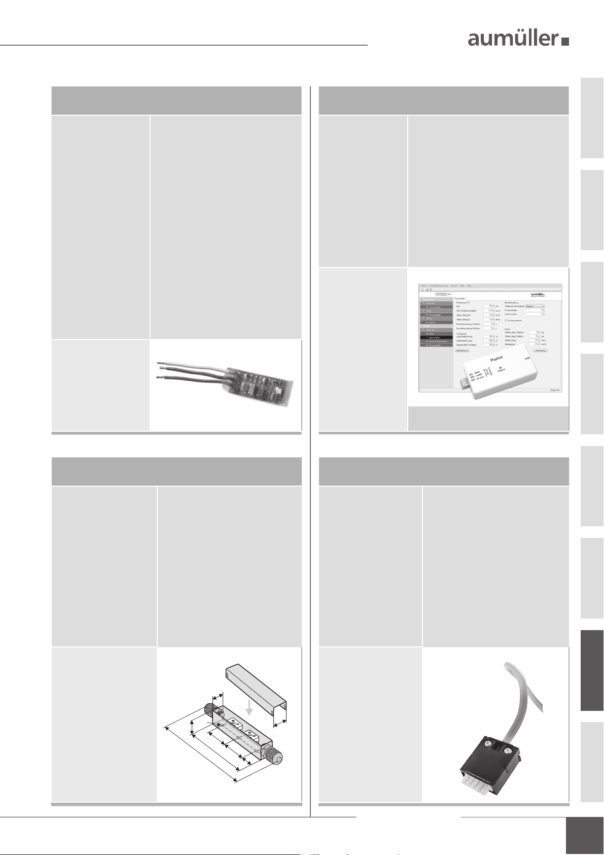
UniPC with con guration interface
Order number:
Application:
Rated voltage:
Parameterizable
drives:
Scope of delivery:
Features /
Equipment:
Power supply 24V DC
is not included in the
scope of delivery!
Any extended settings
require a software
licence.
524178
Hard- and software for con guration of
drives supplied by A
UMÜLLER GmbH
24V DC +/-20%
24V DC type MP, S3, S12, S12 V.2
230V AC type S12, S12 V.2
software UniPC (Downloadlink*), Interface
“ParInt”, USB cable, connection cable
* http://www.aumueller-gmbh.de/Downloads
Cable junction box (for renewal)
Order number:
Application:
Rated voltage:
Material:
Protection class:
Dimensions:
Equipment:
513344
to extend a drive cable
only for low voltage
to max. 50V DC/AC
stainless steel (V2A)
IP 40
25 x 27 x 150 mm
with cable gland (grey)
including strain relief,
with loose ceramic terminals.
5
,
1
2
Ø5
7
2
4
0
c
a
4
.
1
5
0
1
1
0
7
1
8
Any recon guration of a drive is entirely at the
user‘s own risk and responsibility.
AUMÜLLER-Click plug solution
Order number:
Application:
Rated voltage:
Connecting cable:
Terminal:
• Flexible cable length
• Connect multiple drives
• Torsion-plug
• Locking hooks prevent
withdrawal of the plug
5
2
under tensile load
• Strain relief by screwing
the housing halves ac cording DIN EN 60335-1
501250 - 1 m cable length - 24 V DC
501258 - 2 m cable length - 24 V DC
501251 - 3 m cable length - 24 V DC
501252 - 5 m cable length - 24 V DC
501253 - 10 m cable length - 24 V DC
Unitary plug-solution for all
UMÜLLER chain drives and
A
UMÜLLER folding arm drives
A
24 V DC (± 20 %), max. 2 Vpp
non-halogen, grey 5 x 0,5 mm
2
to 1,5 mm2 - 5 piece
07
Assembly Instruction
FVM2
25

ELECTRIC CONNECTION
ELECTRIC CONNECTION CONFIGURED WITH M-COM
Multi-drive operation with M-COM and locking drive - series connection
235
235
Individual
expansion
235
BU
BN
WH
1
12
23
FVM2
drive
drive drivelocking drive
1x M-COM
WH
polarity
reversal
+
-
+
-
M-COM
BN BU
A maximum of three individual
drives and one locking drive in se-
ries connection possible.
Con guration is done by M-COM.
Multi-drive operation with M-COM and locking drive - star wiring
KS 4KS 4KS 4FVM2
brown
BN =
BU = blue
WH =
white
07
07
Options:
Programmable special functions and sequence control with
locking drive. In composite can be used to four individual
drives and two locking drives.
Con guration is done by M-COM.
The universal plug allows the use of cable provided by the
customer. It simpli es the installation and electrical connection
of the drive.
235
+
BN
BU
BN
WH
-
BU
BNBUWH
FVM2
locking drive
24V
+/- +/-
M-COM
KS 4KS 4
junction box
site-supplied
235
Individual
expansion
brown
BN =
BU = blue
WH =
white
26
Assembly Instruction
FVM2

ELECTRIC CONNECTION / SAFETY CHECK
INSTALLATION STEP 8:
SUPPLY LINES OF CONTROL UNIT TO THE DRIVES
Observe current regulations and guidelines e.g. DIN 410212 regarding the “Fire behavior of building materialscircuit integrity maintenance of electric cable systems“
(E30, E60, E90) and the “Specimen Guideline on Conduits
German designation - MLAR“, and also prescribed constructional regulations!
For safety reasons a cable of the next hig-
RECOMMENDATION
Formula to calculate
the required wire cross-section of a supply line
2
A
mm
=
Available data:
• cut-off current per drive (i. e. 2 x 4.0A) from data sheet
• length to be bridged from the last window to the control unit
(i. e. 10 meters)
(2 * 4,0A) * 10m * 2
A =
2,0V * 56m / (Ω*mm
A = 1,42mm2 -> 1,5mm2 chosen
her wire cross section should be selected.
L2
I
A
(total)
2,0 56
V
(voltage drop)
m
*
(length supply line)
m / (Ω*mm
*
Calculation example
2
)
*
2
)
24V
INSTALLATION STEP 9:
SAFETY CHECK AND TEST RUN
Check the mounted system for its safety; perform test run
and commissioning.
Safety test:
• Connect operating voltage.
• Check fastening (frame brackets, casement brackets)
for rm t or tightening.
Test run:
• Visual inspection of casement movements.
• Stop immediately by malfunction!
• Pay attention to collision with facade construction and
correct installation, if required.
Risk evaluation:
Before operating a power-operated window to which
window drives were mounted, which were sold by the
manufacturer as incomplete machines according to installation declaration, the possible risk to ahazard of persons
must be determined, evaluated and minimized by taking
appropriate technical measures in accordance with the Machinery Directive. Separate documents for performing a risk
assessment can be downloaded from the homepage of
Firm A
UMÜLLER AUMATIC GmbH
(www.aumueller-gmbh.de).
Laying and connecting the drive cable
• Avoid extreme temperature differences in the instal lation area (danger of condensation).
• Set clamping point close to window and ensure
accessibility.
• Ensure expansion possibilities of the drive and the drive
cable.
• Consider the cable length and the cross sections of
the drives supply lines.
Operation of the power-operated window
When operating the power-operated window safety
instructions must be observed, speci cally those pertaining
to commissioning, operation and maintenance.
07
Assembly Instruction
FVM2
27

MAINTENANCE AND REPAIR
HELP IN CASE OF MALFUNCTIONS, REPAIRS AND
M
AINTENANCE
Professional repair of a defect drive can only be performed at the
manufacturer’s factory or manufacturer-certi ed specialist company.
Unauthorized opening or manipulation of the drive terminates warranty.
1. Exchange defect drives or have them repaired by the manufacturer.
2. In case of problems during installation or normal operation the
following table might be useful:
Problem Possible causes Possible solutions
Locking drive
does not start
07
• Duration of mains
power supply too short
• Drive run direction from
the opening drive is not
correct
• Connecting cable not
connected
• DIP switch is wrong
setting
• Adjust supply voltage
as speci ed in the
technical documentation
• Check drive cables
change polarity
• Check all connection
cables
• Setting the DIP switch
properly
MAINTENANCE AND MODIFICATION
To ensure continuous function and safety of the drive periodic maintenance by a specialist company is required at least once a year (as mandated
by law for smoke and heat exhaust systems). Operational readiness must
be checked regularly. Frequent inspection of the system for imbalance
and signs of wear or damages of cables and fastening elements must be
performed.
During maintenance contaminations must be removed from the drive.
Fastenings and clamping screws must be checked for tightness. Test runs
during the opening and closing procedure of the devices must be performed.
The drive itself is maintenance-free. Defect devices may only be repaired
in our factory. Only replacement parts of the manufacturer may be used.
When the connection cable of this device is damaged it must be replaced
by the manufacturer or his customer service or a similarly quali ed person to avoid endangerment.
It is recommended to conclude a maintenance contract. A sample maintenance contract can be downloaded from the homepage of
Firm Aumüller Aumatic GmbH
(www.aumueller-gmbh.de).
While cleaning the windows, drives may not have direct contact with
water or cleaning agents. Drives must be protected from dirt and dust
during the construction phase or renovations.
Maintenance process
1. Open or extend power-operated casement completely.
2. Completely disconnect the system from the mains and secure it
against automatic or manual activation.
3. Check windows and ttings for damages.
4. Check all mechanical fastenings (if required, observe information on
torques in installation instructions).
5. Check electric drives for damages and contaminations.
6. Check connecting cables (drive cable) for:
- tightness of the cable screw
- functionality of the strain relief
- damages
7. Check the mobility of hinges and ttings and re-adjust or apply
lubricant, e.g. silicone spray (observe the instructions of the manu facturer of this window system).
8. Check peripheral seal, remove contaminations or replace.
9. Perform cleaning to maintain functionality (e.g. clean extending
elements of the drive, such as chains or spindles by damp wiping them
with acid or lye-free agents and drying them and, if required, lubricate
them with cleansing oil e.g., Ballistol).
10. Turn on operating voltage.
11. Open and close the power-operated window via the operating
voltage (functional test).
12. If available, check and re-adjust protection systems of the safe guard
xture.
13. Check the intactness of the CE label at the power-operated system
(e.g. SHEV/Natural smoke and heat exhaust ventilators).
14. Check the intactness of warning instructions and labels at the
respective drive.
15. Perform a risk assessment in accordance with Machinery Directive
2006 / 42 / EG, if required, e.g. after modifying the machine.
28
Assembly Instruction
FVM2

DISPOSAL / WARRANTY
WARRANTY AND CUSTOMER SERVICEDEMOUNTING
The drives are demounted by reversing the steps, as for the installation.
The adjustments are omitted.
1. Completely disconnect the system from the power supply before
demounting a drive.
2. After demounting a drive the window must be secured against in dependent opening.
Dispose of parts according to the locally applicable legal provisions.
DISPOSAL
According to the European Directive 2012/19 / EU on Waste Electrical
and Electronic Equipment (WEEE) and its transposition into national law,
obsolete electrical appliances must be collected separately and sent for
environmentally friendly recycling.
In principal apply our:
„General Terms for the Supply of Products and Services of the
Electrical Industry (ZVEI)“.
The warranty corresponds with legal provisions and applies to the
country in which the product has been acquired.
The warranty includes material and manufacturing defects incurred
during normal use.
The warranty period for delivered material is twelve months.
Warranty and liability claims for personal injuries or material damages
are excluded, if caused by one or more of the following:
• No proper incoming goods inspection.
• Improper use of the product.
• Improper installation, commissioning, operation, maintenance or
repair of the product.
• Operating the product by defect and improper installed or not
functioning safety and protection devices.
• Ignoring instructions and installation requirements in these in structions.
• Unauthorized constructional modi cations at the product or
accessories.
• Disaster situations due to effects of foreign bodies and Acts of God.
• Wear and tear.
Contact persons for possible warranty claims, for spare parts or
accessories are the employees of the responsible branch of ce or the
responsible person at
UMÜLLER AUMATIC GmbH.
Firm A
Contact data are available at our homepage
(www.aumueller-gmbh.de)
LIABILITY
We reserve the right to change or discontinue products at any time
without prior notice. Illustrations are subject to change. Although we take
every care to ensure accuracy, we cannot accept liability for the content
of this document.
Assembly Instruction
FVM2
08
29

08
30
Assembly Instruction
FVM2

CERTIFICATE AND
ECLARATION OF CONFORMITY
D
We declare under our sole responsibility that the product
described under "Data sheet" is in conformity with the
following directives:
• 2014/30/EU
Directive relating to Electro-Magnetic Compatibility
• 2014/35/EU
Low voltage Directive
We further declare that the drive is an incomplete
machine within the meaning of the European Machinery
Directive (2006/45/EG).
Technical le and declaration at rm:
A
UMÜLLER AUMATIC GmbH
Gemeindewald 11
D-86672 Thierhaupten
Ramona Meinzer
Managing Director (Chairman)
NOTE:
The proof of the application of a quality management
system is for company:
UMÜLLER AUMATIC GmbH
A
according to the certi cation basis DIN EN 9001 as well
the "Declaration of Incorporation and Conformity" can
be accessed via the QR code or directly on our homepage:
(www.aumueller-gmbh.de)
TRANSLATION OF THE ORIGINAL INSTRUCTIONS (GERMAN)
Important note:
We are aware of our responsibility, which is why we present life-supporting and value-preserving products with greatest possible conscientiousness. Although we
make every effort to ensure that the data and information are as correct and up-to-date as possible, we still cannot guarantee that they are free from mistakes and
errors.
All information and data contained in this document are subject to alterations without prior notice. Distribution and reproduction of this document as well as the
use and disclosure of its content is not authorized unless expressly approved. Offenders will be held liable for the payment of damages. All rights reserved in the
case of a patent award or utility model registration.
Basically the General Terms and Conditions of A
The publication of these assembly and commissioning instructions supersedes all previous editions.
UMÜLLER AUTOMATIC GmbH apply to all offers, supplies and services.
Assembly Instruction
FVM2
08
31

AUMÜLLER AUMATIC GMBH
Gemeindewald 11
86672 Thierhaupten
Tel. +49 8271 8185-0
Fax
+49 8271 8185-250
info@aumueller-gmbh.de
9000000701_V1.2_KW11/19
 Loading...