

Assembly and Commissioning
Instructions
according to Machinery Directive 2006 / 42 / EC (annex VI)
FTA600 R / FTA600 DF / FTA600 GF - FOLDING ARM DRIVES

CONTENTS
Abbreviations
Target Groups
Warning and Safety Symbols
Intended Use
01
Safety Instructions
Data sheet FTA600 R S12 24V DC
Data sheet FTA600 DF S12 24V DC
Data sheet FTA600 GF S12 24V DC
Explanations on the product label
02
Areas of Application and Casement Sizes
3 - 8
9 - 11
03
INSTALLATION STEP 1: Inspection before the installation
INSTALLATION STEP 2: Installation prerequisite and Installation preparation
04
INSTALLATION STEP 3: Drill holes according to mounting variants
INSTALLATION STEP 4A: FTA600 R - Opposite hinge side mounting - outward opening door
INSTALLATION STEP 4B: FTA600 R - Hinge-side mounting - inward opening door
INSTALLATION STEP 4C: FTA600 DF - Hinge-side mounting - inward opening side-hung window
05
INSTALLATION STEP 4D: FTA600 GF - Opposite hinge side mounting - outw. open. side-hung window
INSTALLATION STEP 5: Cable routing
INSTALLATION STEP 6: Electric Connection
INSTALLATION STEP 6: Supply lines of drives to the control unit
INSTALLATION STEP 8: Safety check and Test run
06
12
13 - 14
15 - 21
22 - 26
Help in case of Malfunctions, Repairs and Maintenance
Maintenance and Modifi cation
07
Removal and Disposal
Liability
Warranty and After-Sales Service
Certifi cates
08
Assembly Instruction
2
FTA 600
27
28 - 31
PRELIMINARY REMARK
ABBREVIATIONS
Index of abbreviations
These abbreviations are used consistently throughout these assembly
& operating instructions. Unless stated differently, all dimensions indicated in this document are in mm. General tolerances in accordance
with DIN ISO 2768-m.
A drive
AK connection cable / drive cable
AP
BD hinge
Fxxx casement bracket
FAB overall width of casement
FAH overall height of casement
FG casement weight
FL casement
FÜ casement overlap
HSK main closing edge
Kxxx frame bracket
L construction lenghth of drive
MB central hinge
NSK side closing edge
RA frame
RAB overall width of frame
RAH overall height of frame
SL snow load
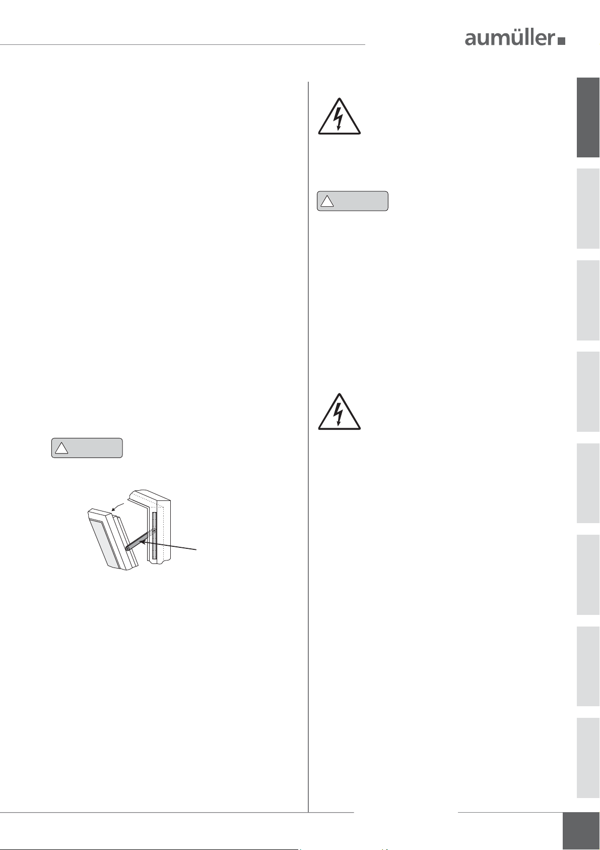
cover cap
opening direction
WARNING AND SAFETY SYMBOLS IN THESE IN-
STRUCTIONS:
The symbols used in the instructions shall be strictly observed and have
the following meaning:
!
DANGER
!
WARNING
!
CAUTION
NOTE
Failure to comply with the warning notes results
in irreversible injuries or death.
Failure to comply with the warning notes can
result in irreversible injuries or death.
Failure to comply with the warning notes can
result in minor or moderate (reversible) injuries.
Failure to comply with the warning notes can
lead to damage to property.
Caution / Warning
Danger due to electric current.
Caution / Warning
Risk of crushing and entrapment during device operation (is provided as a sticker with the drive).
01
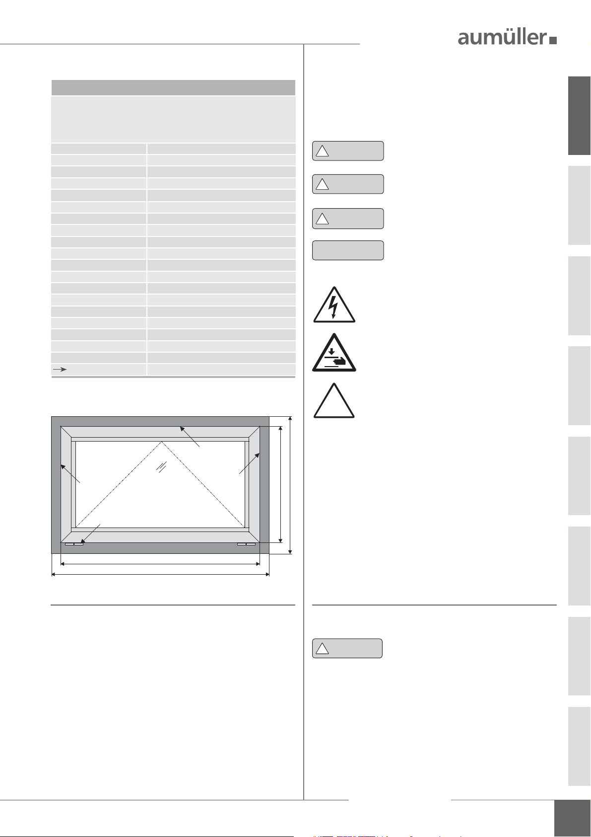
RA
FL
HSK
NSK
BD
FAB
RAB
NSK
FAH
RAH
TARGET GROUP
These instructions are intended for trained personnel
and operators of systems for natural smoke ventilation
(NRA / SHEV) (natural smoke exhaust system / smoke and
heat exhaust system) and natural ventilation via windows,
who are knowledgeable of operating modes as well as the
remaining risks of the system.
Attention / Warning
Risk of damage to / destruction of drives and / or
!
!
WARNING
windows.
This device is not intended for use by per-
sons (including children) with physical,
sensory or mental limitations or lacking experience and / or
knowledge, unless they are supervised by a person who is
responsible for the safety or were instructed by him on the
usage of this equipment. Children should be supervised to
ensure that they are not playing with this device.
Cleaning and operator’s maintenance may not be performed by children without supervision.
Assembly Instruction
FTA 600
3

INTENDED USE
Area of application / Scope of application
This drive is intended for the electromotive opening and
closing of windows in facade and roof areas.
The prime task of this product, in combination with
a window and a suitable external control unit, is to
01
evacuate hot smoke and combustion gases in case
of re, to safe human lives and protect material
assets. Furthermore, combined with a suitable external
control unit, the electromotive operated window ensures
fresh air supply for the natural ventilation of the
building.
By attaching the drive to a movable
element of the window a so-called
NOTE
Intended use according to the Declaration of Conformity
The drive is intended for stationary installation and
electrical connection at the window as part of a building.
In accordance with the attached Declaration of Conformity the drive, in combination with an external Control
Unit from A
power-operated window without an additional on-site
risk assessment for the following use:
• Application for natural ventilation
2,5 m above the oor, or
element of < 200 mm by a simultaneous speed of
< 15 mm/s at the HSK in closing direction.
• Application as NSHEV (natural smoke and heat
exhaust ventilators) for ventilation without dual
function for ventilation in accordance with
EN12101-2.
with an installation height of the drive of at least
with an opening width at the HSK of the operated
“power-operated window” is created
which, according to the Machinery
Directive 2006 / 42 / EG, represents a
machine.
UMÜLLER, is released for its intended use at a
PRELIMINARY REMARK
We as manufacturers are well aware of our duties and
responsibilities regarding the development, manufacturing and placing of safe window drives on the market and
consistently implement them. Ultimately, however, we have
no direct in uence on the usage of our drives. Therefore,
as a precaution, we point out the following:
• The constructor or his agent (architect, specialist
planner) are obligated by law to evaluate the
hazards to persons, originating from the usage,
installation position, opening parameters as well as
the planned type of installation of the power
operated window and the external Control Unit,
already in the planning phase and to establish
necessary protective measures.
• The constructor / manufacturer of the machine
“power-operated window” must implement the
planned protective measures at the installation site
or, if not yet established, determine them by theire
own responsibility and detect or minimize possible
remaining risks.
The need for a risk assessment at the installation site
due to the reasonably foreseeable misuse.
A risk assessment in accordance with the Machinery
Directive 2006 / 42 / EG for the usage of the power-
operated window for natural ventilation is absolutely
necessary under the following conditions:
• the installation height of the drive is < 2,5 m above the
oor and
• the opening width at the HSK > 200 mm, or
• the closing speed at the HSK is > 15 mm/s, or
• the opening speed at the HSK is > 50 mm/s, or
• the closing force at the HSK is > 150 N
The following ow chart can be applied, which also includes
the protective measures in accordance with EN 60335-2103/2016-05.
Attention must be paid to possible
hazards when used with tilting or
rotating windows, whose secondary
!
WARNING
closing edges are located at less than
2,5 m installation height above the oor,
under consideration of the Control Unit
and usage!
Assembly Instruction
4
FTA 600
PRELIMINARY REMARK
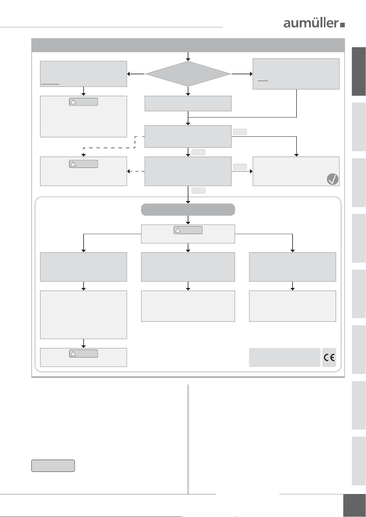
Risk analysis in accordance with DIN EN 60335-2-103
NSHEV in accordance
with EN12101-2
without dual purpose for ventilation
CAUTION
!
Risk analysis is not required!
Keep people away during closing!
By opening width of > 200 mm,
close via hold-to-run switch!
CAUTION
!
Observe danger at NSK
< 2,5 m above oor!
Using drives
Natural ventilation
Installation height of drive:
> 2,5 m above oor
(ZAA.20.1)
No
Opening at HSK: < 200 mm and
Speed at HSK:
CLOSE <15 mm/s / OPEN < 50 mm/s
(20.ZAA.2)
No
RISK EVALUATION
CAUTION
!
Protection devices
Yes
Yes
NSHEV in accordance
with EN12101-2
with dual purpose for ventilation
(1.Z.109)
Risk covered by
Declaration of Conformity
for window drives
01
Hold-to-run switch:
stops movement at HSK < 20 mm
at a closing force of > 150 N at HSK
(20.ZAA.5)
Operating element in
direct range of vision:
a.) Key switch or
b.) other switch,
then: installation > 1,5 m,
inaccessible for public
(7.12.1)
CAUTION
!
Keep people away during closing!
Contact-free anti-trap protection
(20.ZAA.8.1)
Passive infra-red and active light sensors
pressure mats
Casement data
Facade: bottom-hung window, top-hung win dow, side-hung window.
Dach: roof window / sky light.
Opening direction: inward / outward opening.
Pro le material: aluminum, steel, plastic or wood.
The casement measurements supplied
NOTE
are only for orientation purposes.
It is imperative that the force-path
diagram of the drives are observed.
Contact-based anti-trap protection
(20.ZAA.8.2)
Pressure-sensitive safety switch strips
or
Motor current monitoring systems
(internal and external)
Declaration of Conformity
for window + CE label
or
When inspecting the drives for conformity with on-site
requirements the following items must be observed:
• total weight of casement (glass + frame),
• additional loads: snow load / wind load
(suction / pressure),
• casement size (FAB x FAH),
• side ratio FAB / FAH,
• installation / inclination angle,
• required opening area (geometric / aerodynamic),
• crosswind in uences,
• driving force and stroke,
• mounting site at the window frame and casement
frame.
Assembly Instruction
FTA 600
5
SAFETY INSTRUCTIONS
It is important to follow these instruc-
!
WARNING
01
Area of application
The drive shall only be used according to its intended use.
For additional applications consult the manufacturer or his
authorized dealer.
!
WARNING
Always check whether the system complies with current
regulations. Special attention must be paid to the opening
width, the opening area, the opening time and the opening
speed of the window, the temperature range of the drives /
external devices and cables as well as the cross section of
the connecting cables as function of the cable length and
power consumption.
!
tions for the safety of persons. These
instructions shall be kept in a safe place
for the entire service life of the products.
Risk of crushing and entrapment!
Window can close automatically!
The integrated load cut-off stops the
drive during closing and opening when
the drive is overloaded.
The compressive force is absolutely
suf cient to crush ngers in case of
carelessness.
Do not misuse the drive for other lifting
operations! Do not allow children to play
with this drive or its regulating and / or
control units, including the remote
control!
All devices must be permanently protected
from dirt and moisture, if the drive is not
explicitly suitable for use in wet areas (see
technical data).
SAFETY INSTRUCTIONS
Installation
These instructions address expert and safety-conscious
electricians and / or quali ed personnel knowledgeable in
electrical and mechanical drive installation.
All speci cations for installation must be checked independently and, if necessary, adjusted at the installation site.
The connection assignment, the electrical supply data (see
machine plate) and performance limits (see technical data)
as well as the mounting and installation instructions of the
drive must be strictly observed and adhered to!
Do not reach into the window rabbet or the operating
element (chain or spindle) during installation and operation! Ensure that, based on the installation position and
the opening movement of the casement, persons cannot
be trapped between the driven part of the window and
surrounding xed components (e.g. wall).
Mounting material
The required mounting material must be modi ed to t the
drive and occurring load and, if necessary, supplemented.
NOTE
NOTE
The safe operation, avoidance of injury to
persons and damage to property, as well
as risks, is only guaranteed by proper
installation and setting according to
these installation instructions.
Never connect 24 V DC drives to 230 V AC
mains voltage!
Danger to life!
Before installing the drive, check whether
the casement is in good mechanical condition, the weight in balance and whether
it opens and closes easily!
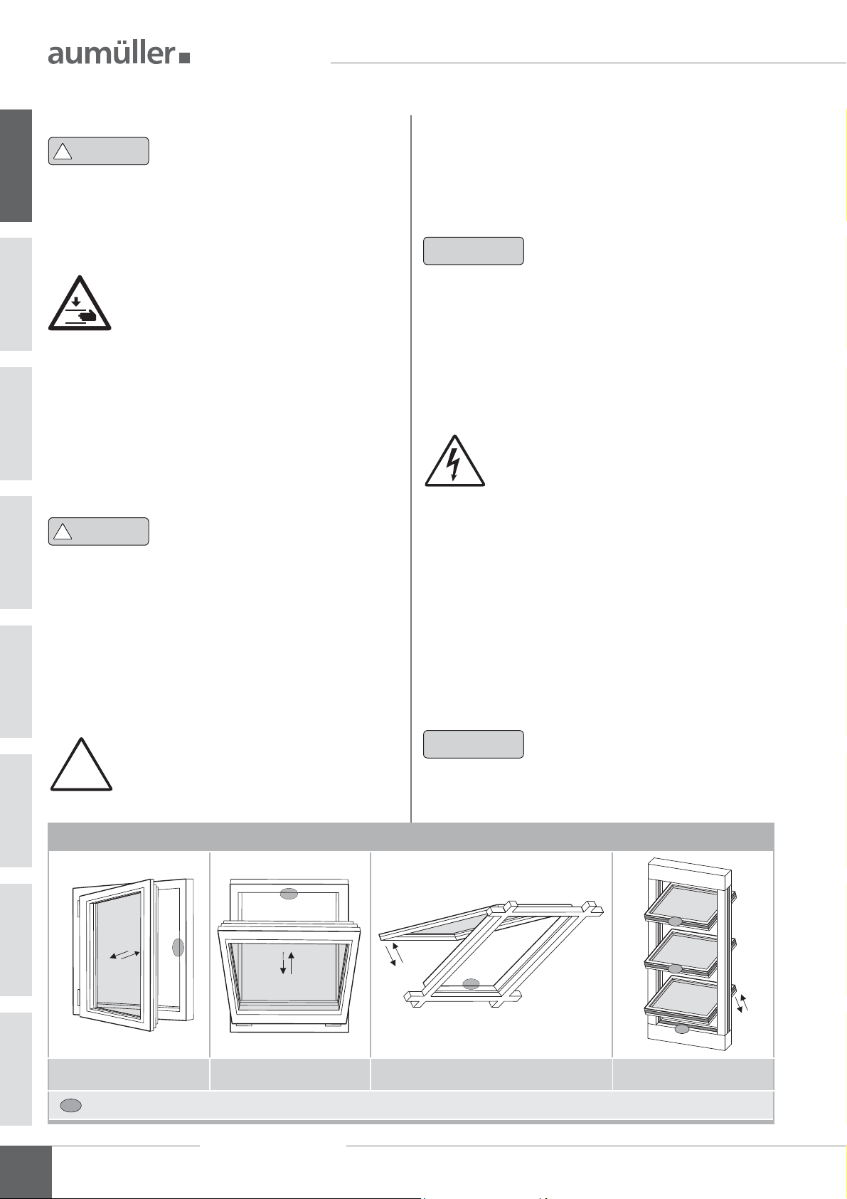
Danger spots by crush and shear points
Side-hung Bottom-hung Roof windows / skyskylight domes Louvre windows
Danger spots: crush and shear points according to DIN EN 60335-2-103
Assembly Instruction
6
FTA 600
SAFETY INSTRUCTIONS
Crush and shear points
To avoid injuries, crushing and shear points between
casement and frame must be secured against entrapment
up to an installation height of 2,5 meters above the
oor with appropriate measures. This can be achieved e.g.
by using contact-based or contactless protective devices
against entrapment, which stop the motion through contact or through interruption by a person. At a force higher
than 150 N at the main closing edge the motion must stop
within 20 mm. A warning symbol at the opening element
must indicate this clearly.
Unintentional or independent opening or falling
Casements are to be hinged or secured such way that in
case one of the mounting elements fails it will not crash /
slam down or move in an uncontrolled manner by e.g. using
double suspensions, safety scissors, casement stays.
Tilting windows shall be equipped with safety scissors or
similar devices to avoid damages and risks of injury for
persons through improper installation and operation. The
safety scissors must be adjusted to the opening stroke of
the drive (see technical data) to avoid blocking. The opening
width of the safety scissors must be bigger than the drive
stroke.
The movable casement must be secured
!
WARNING
against unintentional or independent
opening as well as falling down.
All-pole disconnecting devices shall be installed in the permanent electrical installation or
external Control Unit for the drive.
The mains supply lines 230 V / 400 V AC shall
be protected separately!
Damaged mains supply lines of drives
with plug connectors may only be re-
placed by the manufacturer or quali ed
!
WARNING
service / maintenance personnel!
Power cables which are xed to the drive
casing cannot be replaced. If the cable is
damaged the device must be scrapped!
The types of cable, cable lengths and cross-sections shall
be selected in accordance with the manufacturer’s technical
data. If necessary, the cable types shall be coordinated with
the competent local authorities and energy supply companies. Low-voltage lines (24 V DC) shall be routed
separate from the high-voltage lines. Flexible cables may
not be ush-mounted. Freely suspended cables shall be
equipped with strain reliefs.
Cables must be laid such way that they cannot
be sheared off, twisted or bent during operation. Drive cables laid into closed window
pro les must be protected by insulating
tubes with a suf cient temperature resistance.
Through holes shall be equipped with cable
sleeves!
Clamping points shall be checked for tightness of threaded connections and cable ends. Access to junction boxes,
clamping points and external drive control systems shall be
ensured for maintenance work.
01
safety scissors
Routing cables and electrical connection
Routing or installing electrical lines and connections may
be performed only by approved specialist companies. Never
operate drives, control units, operating elements and sensors at operating voltages and connections contrary to the
speci cations of the manufacturer.
All relevant instructions shall be observed for the installation, speci cally:
• VDE 0100 Setting up high-voltage systems up to 1000 V
• VDE 0815 Wiring cables
• Specimen Guideline on Conduits German designation
(MLAR).
Commissioning, operation and maintenance
After the installation and after each modi cation in the set
up all functions shall be checked with a trial run. It shall
be ensured that drive and casement are set correctly and
that security systems, if available, are functioning properly.
After the installation of the system is completed the
end-user shall be introduced to all important operating
steps. If necessary, he must be advised of all remaining risks /
dangers.
The end-user shall be instructed in intended use of the
drives and, if necessary, the safety instructions. The end-user
shall be speci cally instructed that no additional forces,
except for the pressure and tension in the opening and
closing direction of the casement, may be applied to the
spindle, chain or lever of the drive.
Assembly Instruction
FTA 600
7

SAFETY INSTRUCTIONS
NOTE
During the proper assembly of drives with mounting
elements at a window, and the connection to an external
01
control unit, the interfaces resulting from mechanical and
electrical performance characteristics of single elements
shall be observed.
!
CAUTION
!
CAUTION
!
CAUTION
Post warning signs!
Other persons must be kept away from
the casement when a hold-to-run switch
(pushbutton) is operated or when a
window, which has been opened by a
smoke and heat exhaust system, is closing!
The operating element of hold-to-run
switches must be installed within direct view from the window, but apart
from moving elements. If the switch is
not a key-operated switch it must be
installed at a minimum height of 1,5 m
and inaccessible to the public!
Do not allow children to play with
permanently mounted control devices
and keep remote controls out of reach
for children!
Replacement parts, fasteners and controls
The drive shall only be operated with control devices from
the same manufacturer. There is no liability, warranty or
customer service if third-party parts are used. Exclusively
original replacement parts of the manufacturer shall be
used for mounting elements or expansions.
Ambient conditions
The product may not be subjected to impacts or falls, or
to vibrations, moisture, aggressive vapors or other harmful
environments, unless the manufacturer released it for one
or more of these environmental conditions.
• Operation:
Ambient temperature: -5 °C … +75°C
Relative humidity: < 90% less 20°C;
< 50% less 40°C;
no formation of condensation
• Transport / Storage:
Storage temperature: -5°C … +40°C
Relative humidity: < 60%
Accident prevention regulations and workmen’s
compensation insurance guidelines
For work on or in a building or building part the provisions and instructions of the respective accident prevention
regulations (UVV and workmen’s compensation insurance
guidelines (BGR /ASR) shall be observed and adhered to.
!
WARNING
During cleaning, maintenance work and while
exchanging parts the drive must be completely disconnected from the power supply and
secured against unintentional reactivation.
Do not use drive or casement when repair
or re-setting work has to be performed!
Declaration of Conformity
The drive is manufactured and inspected in accordance with
European guidelines. The respective Declaration of Conformity is on hand.
In case the operation of the drive differs from the
intended use, a risk evaluation for the complete
power-operated window system shall be performed
and a Declaration of Conformity according Machinery
Directive 2006 / 42 / EG issued.
Assembly Instruction
8
FTA 600

DATA SHEET FTA600 R S12 24V DC
Application: natural ventilation, SHEV
Mainly for opening of doors as air intlets
Internal intelligent cut-off switch S12
Programmable contact for door opener
Unitary plug-solution for all A
Options
Programmable special functions
M-COM for automatic synchronised run of multi drive systems and automatic sequence
control with FV locking drives (S3/S12 SW V2)
Various customised programmings on request
TECHNICAL DATA
40
6,5
ø5,5 (4x)
56
16
24
U
Rated voltage 24V DC (± 20 %), max. 2 Vpp
N
I
Rated current 1,0 A
N
I
Cut-off current 1,4 A
A
P
Rated power 24 W
N
ED Duty cycle 30 % (ON: 3 min. / OFF: 7 min.)
DATA SHEET
UMÜLLER chain drives and AUMÜLLER folding arm drives
02
L = 421
Protection rating IP 32
max. 93°
20
405
Ambient temperature range -5 °C ... +75 °C
M
Torque OPEN 215 Nm (600 N)
A
Torque CLOSE 215 Nm (600 N)
M
Z
Pullout force no connection to the moving parts (roll)
F
H
Lever arm aluminium (RAL9006) with plastic roll
Connecting cable with plug non-halogen, grey 5 x 0,5 mm², ~ 3 m
t Running time (0° - 90°)
45 s (2,0°/s) 45 s (2,0°/s)
s Window-opening angel 0° – 93° (± 5 %)
L Length 421 mm
86
24 V DC
5
12,5
Sound pressure level A 70 dB (A)
Potential free contact max. 24V DC / 0,5A programmable
ORDER DATA
s [DEG] L [mm] Version Finish PU / pcs. Part.-No.
0˚ – 93˚ 421 FTA600 R S12 24V E6/C-0 1 524144
ACCESSORIES
K88 Frame bracket FTA600 R 1 524156
PU / pcs. Part.-No.
OPTIONS
Special model PU / pcs. Part.-No.
Drive housing painted/powder coated in other RAL colours
Specify at order stage: 516004
Microprocessor programming S12
Electrical stroke reduction 1 524190
Special functions 1 524180
Optional accessories PU / pcs. Part.-No.
M-COM Comm. module for synchronised multi-drive systems 1 524177
Assembly Instruction
FTA 600
9

DATA SHEET FTA600 DF S12 24V DC
02
40
6,5
ø5,5 (4x)
56
16
24
DATA SHEET
Application: natural ventilation, SHEV, ferralux®-NSHEV
Mainly for opening and closing of side-hung inward opening windows
Internal intelligent cut-off switch S12
Programmable contact for door opener
Unitary plug-solution for all A
Options
Programmable special functions
M-COM for automatic synchronised run of multi drive systems and automatic sequence
control with FV locking drives (S3/S12 SW V2)
Various customised programmings on request
TECHNICAL DATA
U
Rated voltage 24V DC (± 20 %), max. 2 Vpp
N
I
Rated current 0,8 A
N
I
Cut-off current 1,4 A
A
P
Rated power 20 W
N
ED Duty cycle 30 % (ON: 3 min. / OFF: 7 min.)
UMÜLLER chain drives and AUMÜLLER folding arm drives
L = 421
Protection rating IP 32
max. 93°
20
M
M
381
Ambient temperature range -5 °C ... +75 °C
Torque OPEN 215 Nm (600 N)
A
Torque CLOSE 215 Nm (600 N)
Z
F
Pullout force 3000 N (fastening depended)
H
Lever arm aluminium (RAL9006)
Connecting cable with plug non-halogen, grey 5 x 0,5 mm², ~ 3 m
t Running time (0° - 90°)
15
s Window-opening angel 0° – 93° (± 5 %)
45 s (2,0°/s) 45 s (2,0°/s)
L Length 421 mm
Potential free contact max. 24V DC / 0,5A programmable
86
M10
24 V DC
Sound pressure level A 70 dB (A)
ORDER DATA
s [DEG] L [mm] Version Finish PU / pcs. Part.-No.
0˚ – 93˚ 421 FTA600 DF S12 24V E6/C-0 1 524145
ACCESSORIES
K103 Frame bracket FTA600 DF 1 524172
PU / pcs. Part.-No.
10
OPTIONS
Special model PU / pcs. Part.-No.
Drive housing painted/powder coated in other RAL colours
Specify at order stage: 516004
Microprocessor programming S12
Electrical stroke reduction 1 524190
Special functions 1 524180
Optional accessories PU / pcs. Part.-No.
M-COM Comm. module for synchronised multi-drive systems 1 524177
Assembly Instruction
FTA 600
DATA SHEET FTA600 GF S12 24V DC
Application: natural ventilation, SHEV, ferralux®-NSHEV
Mainly for opening and closing of side-hung outward opening windows
Internal intelligent cut-off switch S12
Programmable contact for door opener
Unitary plug-solution for all A
Options
Programmable special functions
M-COM for automatic synchronised run of multi drive systems and automatic sequence
control with FV locking drives (S3/S12 SW V2)
Various customised programmings on request
40
6,5
L = 421
ø5,5 (4x)
56
16
24
max. 93°
20
450
444
24 V DC
7
TECHNICAL DATA
U
Rated voltage 24V DC (± 20 %), max. 2 Vpp
N
I
Rated current 0,8 A
N
I
Cut-off current 1,4 A
A
P
Rated power 20 W
N
ED Duty cycle 30 % (ON: 3 min. / OFF: 7 min.)
Protection rating IP 32
Ambient temperature range -5 °C ... +75 °C
M
Torque OPEN 215 Nm (600 N)
A
M
Torque CLOSE 215 Nm (600 N)
Z
F
Pullout force 3000 N (fastening depended)
H
Lever arm aluminium (RAL9006)
Connecting cable with plug non-halogen, grey 5 x 0,5 mm², ~ 3 m
t Running time (0° - 90°)
s Window-opening angel 0° – 93° (± 5 %)
L Length 455 mm
Potential free contact max. 24V DC / 0,5A programmable
Sound pressure level A 70 dB (A)
DATA SHEET
UMÜLLER chain drives and AUMÜLLER folding arm drives
02
45 s (2,0°/s) 45 s (2,0°/s)
86
117
27
ORDER DATA
s [DEG] L [mm] Version Finish PU / pcs. Part.-No.
0˚ – 93˚ 455 FTA600 GF S12 24V E6/C-0 1 524146
ACCESSORIES
K104 Frame bracket FTA600 GF 1 524173
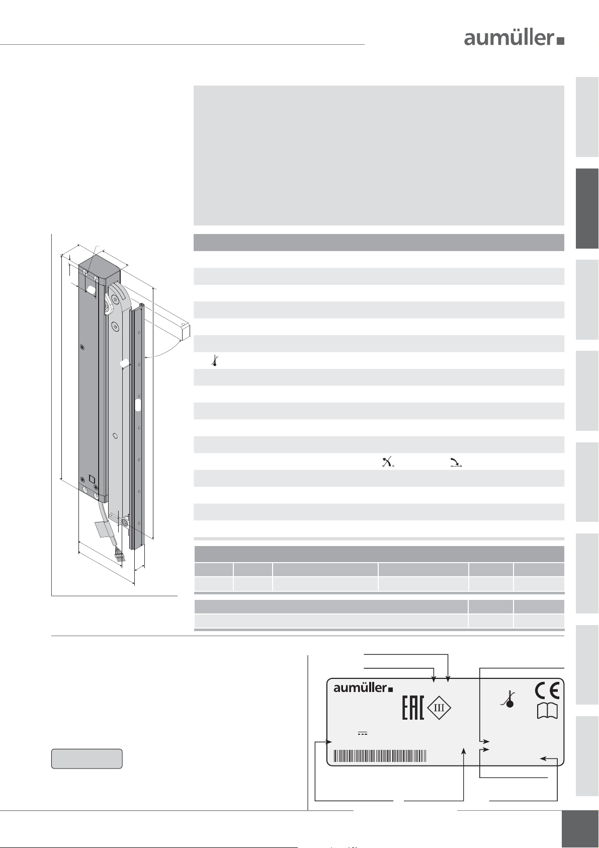
EXPLANATIONS ON THE PRODUCT LABEL
The product label provides information about:
• manufacturer,
• article reference number and name,
• technical caracteristics,
• date of manufacturing with rmware version,
• serial number.
NOTE
In the event of any complaints, please indicate the
product serial number (SN) (see product label).
Never install and operate damaged
products.
overload disconnection
with slide rail
D-86672 Thierhaupten
Gemeindewald 11
Tel. +49 8271 / 8185-0
s: 0° - 93°
U
: 24V 2 V
N
IA: 1,4 A
symbols see
„Technical data“
FTA600 GF S12 24V
F
: 3000 N
H
IP: 32
pp
ED: 3 min / 7 min (on/off)
Duty cycle
ON: 3 minutes
OFF: 7 minutes
PU / pcs. Part.-No.
date of manufacturing
with rmware version
+75°C
-5°C
Made in Germany
Date: 16W01 V:2.0
SN: 41049322007
Art.-Nr.: 524146
serial number
article reference
number
Assembly Instruction
FTA 600
i
11

REPARING ASSEMBLY
P
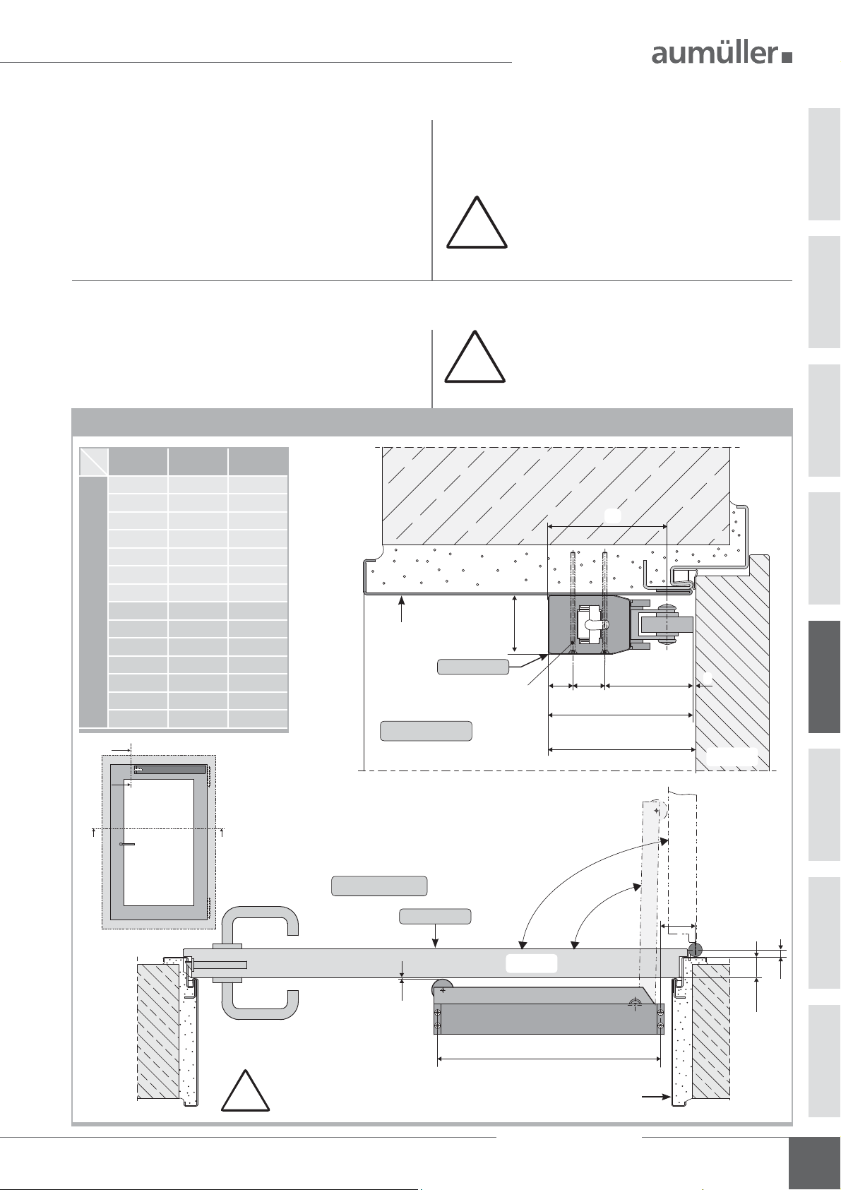
AREAS OF APPLICATION AND CASEMENT SIZES
Areas of Application and Casement Sizes
Door - inward opening
Hinge-side mounting
at the upper side closing edge
FTA600 R FTA600 R
Door - outward opening
Opposite hinge side mounting
at the upper side closing edge
Roof window - inward opening
Hinge-side mounting
at the side closing edges
FTA600 DF FTA600 GF
Roof window - outward opening
Opposite hinge side mounting
at the side closing edges
03
Space on the frame:
above min. 56 / max. 106 mm
door width: < 1200 mm
door height: < 2000 mm
total weight: < 100 kg
with K88 frame bracket FTA600 R without casement bracket with K103 frame bracket FTA600 DF with K104 frame bracket FTA600 GF
Space on the frame:
above min. 40 mm
door width: < 1200 mm
door height: < 2000 mm
total weight: < 100 kg
Space on the frame:
above min. 48 mm
casement width: < 1200 mm
casement height: < 1500 mm/solo
casement height: < 2500 mm/tandem
Space
on the frame: min. 60 mm
on the casement:
casement width: < 1200 mm
casement height: < 1500 mm/solo
casement height: < 2500 mm/tandem
min. 40 mm
12
Assembly Instruction
FTA 600

REPARING ASSEMBLY
P
INSTALLATION STEP 1: INSPECTION BEFORE THE INSTALLATION
Important instructions for a safe instal-
!
WARNING
lation. Observe all instructions, wrong
installation may result in serious injury!
Storage of drives at the construction site
Protective measures against damages, dust, moisture or
contamination shall be taken. Store drives intermediately
only in dry and well ventilated rooms.
Inspection of drives before installation
Check drives and window before installation for good
mechanical condition and completeness. The chains / spindles of the drives must be extendable or retractable easily.
The casement must run smoothly and the weight must be
in balance.
We recommend the use of our test kit for
the inspection of drives with the rated
NOTE
voltage 24V= / 230V~ (see table below).
Damaged products may not be operated
under any circumstance.
Test kit for drives
Order number:
Application:
Supply voltage:
Drive types:
Drive current:
Display:
Ambient temperature:
Plastic housing:
Weight:
Feature / equipment:
533981
Test kit to check running direction and
communication of drives 24V DC or
230V AC (including batteries)
230V AC
24V DC / 230V AC
max. 3 A
drive current, battery charge
-5 °C ... + 75 °C
250 x 220 x 210 mm
approx. 3,6 kg
Control elements: 2 switches + 1 button
The test procedure of drives may only be performed on a
non-slip and secured mat or a test xture. During the test
run the test element must not be interfered with. The test
my only be conducted by or under the supervision of expert
personnel.
For testing chain drives the chain must be extended and
retracted at an angle of approx. 90°. The spindle tubes of
spindle drives in round housing tubes must be secured
against independent spinning before starting the test to
avoid deviations in the position encoder.
Inspection of the intended use
The planned use of the drive must be checked for compliance with its intended use. If used otherwise the liability
and warranty claim expires.
Predictable misuse
It is imperative that foreseeable misuse of drives is avoided!
Here are a few examples:
• do not connect 24 V DC drives to a 230 V AC mains
voltage,
• observe synchronous run and sequence control by drives
with multiple interconnection,
• use drives only indoors,
• avoid additional force in uences, e.g. transverse forces.
Testing mechanical requirements
Prior to the start of the installation check whether :
• the support surface and the pro le static for the load
transmission is suf cient,
• a support construction for the secure fastening of the
drives is required,
• cold bridges (thermal separation) are avoidable at
action points,
• there is suf cient space for the swivel movement of the
drive.
If not, counter measures must be taken!
The support surface of the frame brackets or
casement brackets must rest completely on
the window or frame pro le. There must be
!
no tilting of the fastening elements during
extension and retraction of the drives. A
safe and solid fastening must be ensured
at the window pro le.
04
!
CAUTION
It is imperative that the suf ciently
mechanical stiffness of the fastener type
as well as of the swivel range of the drive
is observed.
If this is not guaranteed another type of
fastening or another type of drive must
be selected.
Assembly Instruction
FTA 600
13

REPARING ASSEMBLY
P
INSTALLATION STEP 2: INSTALLATION PREREQUISITE AND INSTALLATION PREPARATION
The following conditions must be ful lled for the installation of the drives so they can be properly assembled with
other parts and constructed to a complete machine at the
window without impairing the safety and health of persons:
1. The design of the drive must ful ll the requirements.
2. The fastening accessories (casement brackets or
frame brackets) must t the window pro le; the
pro le-dependent hole lay-out must be complied with.
3. The space required for the installation of the drive on
the frame and casement pro le must be suf cient.
4. The window must be in perfect mechanical condition
before the installation. It should open and close easily.
5. The fastening material for the installation of the drive
must t the window material (see table).
wood screws:
i.e. DIN 96, DIN 7996, DIN 571
with head-type:
round head with slot,
04
round head with cross,
Wood windows
hex head,special type
self-tapping screws, thread screws,
sheet-metal screws
i.e. ISO 4762, ISO 4017, ISO 7049 , ISO 7085, DIN 7500
with head-type:
cylinder head with hex socket, internal serration (Torx),
Phillips head or external hex head
aluminum windows
steel, stainless steel,
blind rivet nut
screws for plastic
i.e. DIN 95606, DIN 95607, ISO 7049,
ISO 7085, DIN 7500
with head-type:
round head with cross, external hex head,
plastic windows
Torx
webs
if possible, screw
Recommendation:
through two cavity
Check window data on site
• Measure FAB and FAH.
• Check / calculate weight of casement.
If unknown, it can be determined approximately with
the following formula:
G (Casement = FAB * FAH * Glass thickness * 2,5 * 1,1
frame
weight) [kg] [m] [m] [mm]
glassdensity
share
• Check / calculate the required drive force and compare
with drive data . If unknown, it can be determined
approximately with the following formula:
F [N] =
Facade Roof
5,4 * G [kg] * s [m] 5,4 * G [kg] * FAH [m]
a [m] a [m]
F [N] =
a = Distance of action point to hinges
s
F = Drive force
s = Stroke
s
G
a
F
FAH
F
a
G
FAH
FAH
a
G
F
s
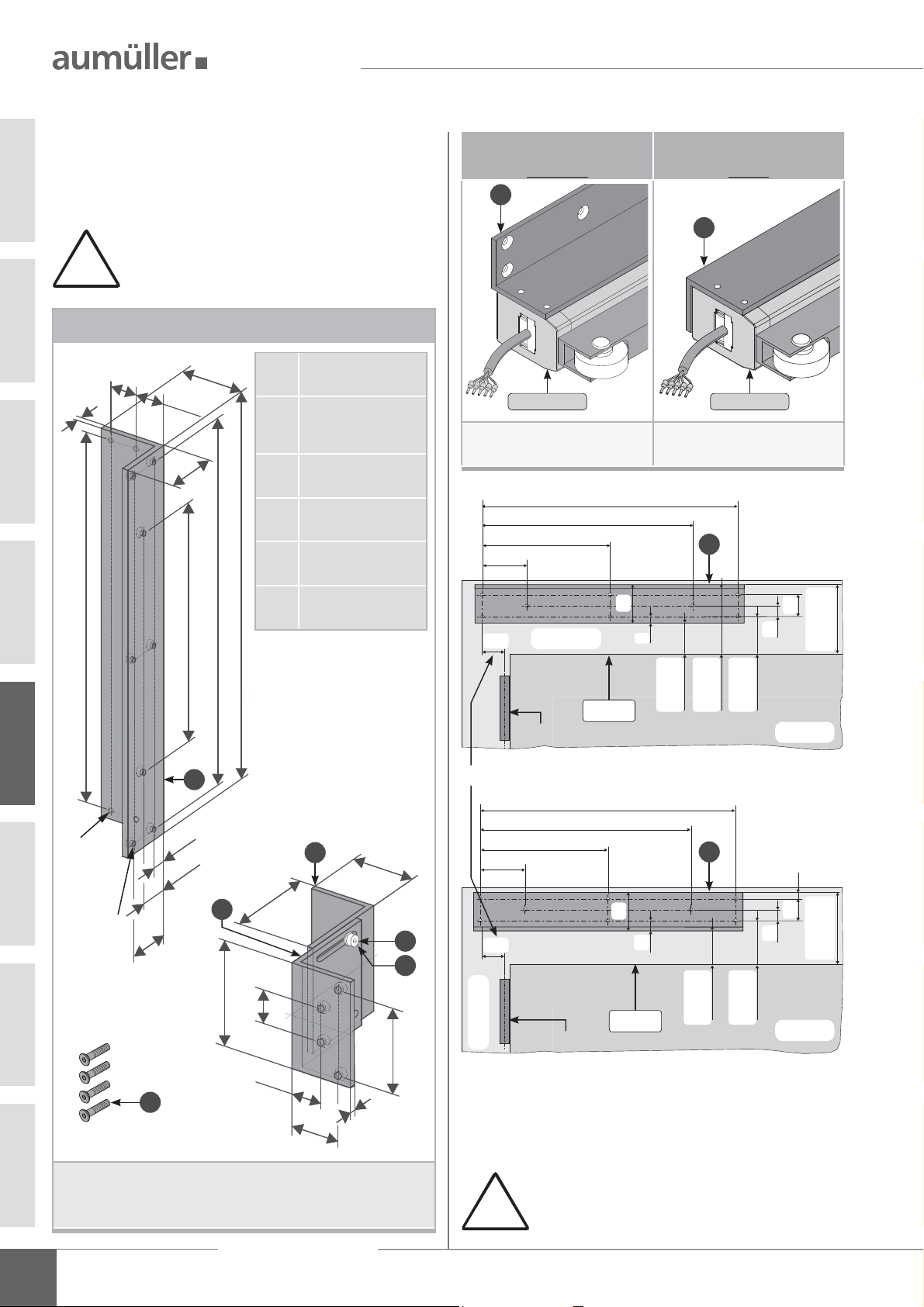
Scope of delivery:
Prior to assembly, check items quantity in the delivery for
completeness.
Accessories for folding arm drives
Assembly and Commissioning
Instructions
UMÜLLER-Click plug solution
24 V DC
A
Warning sign sticker
„Risk of entrapment“ (1x)
Tools required
• Marker,
• Grains,
• Hammer,
• Knife,
• Screwdriver (cross, Torx),
• Hexagonal wrench,
• Torque wrench,
• Power drill,
• Threadlock adhesive,
• possibly a tool for blind rivet nuts.
Assembly Instruction
14
FTA 600
Only at:
1x Slide rail 450 mm
1x Slide 40 x 20
1x Connector 40 x 20 x 20 mm
1x Bolt ø12 x 20 mm
1x Screw M6 x 25
1x Circlip DIN 472
2x Screw M4 x 8
2x Lock washer DIN 127
FTA600 GF
OUNTING FTA600 R
M
INSTALLATION STEP 3:
Determine fastenings.
Produce drill holes with appropriate cross-section.
DRILL HOLES ACCORDING TO MOUNTING VARIANTS
Secure fasteners against loosening; e.g. by applying
removable thread-locking compound such as “Loctite”.
For the mounting dimensions please refer to the
following hole layout drawings or project-speci c
documents and drawings.
!
Carefully clear away drilling swarfs to prevent
seals from being damaged.
Avoid surface scratches, for example by using
masking tape.
I
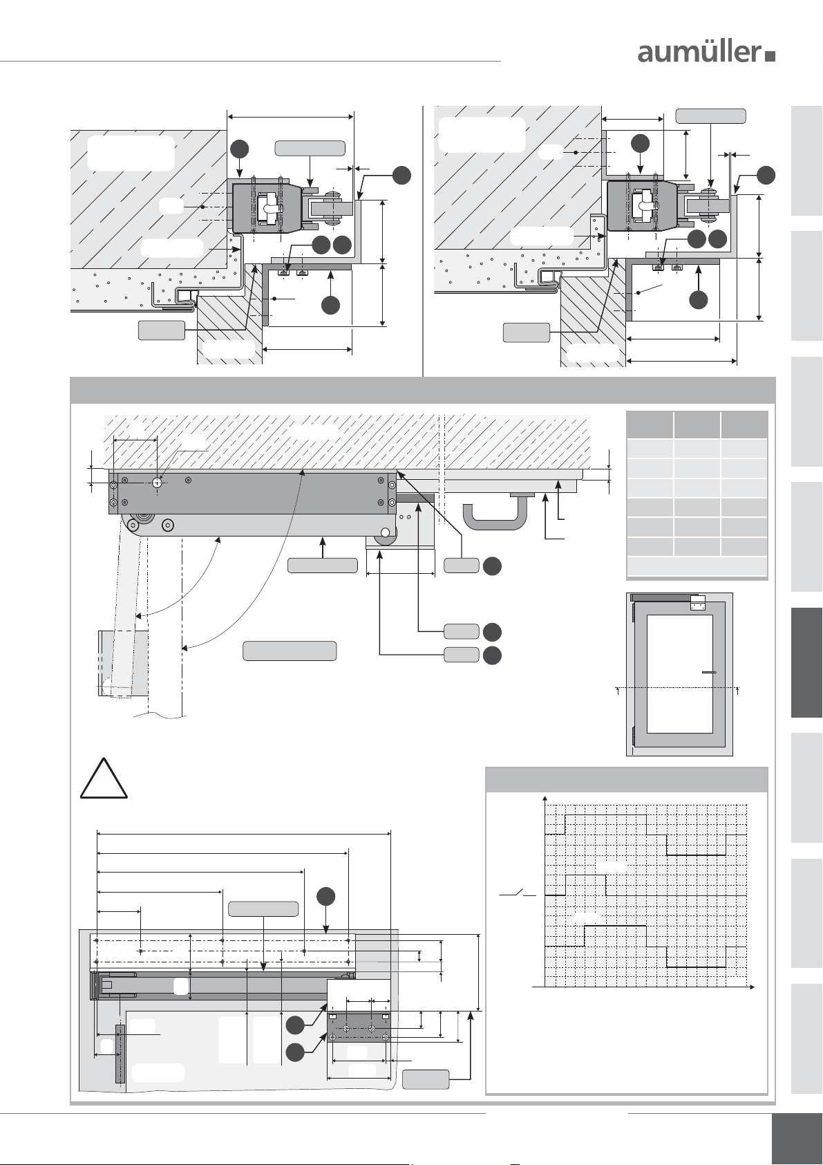
NSTALLATION STEP 4A:
FTA600 R - OPPOSITE HINGE SIDE MOUNTING - OUTWARD OPENING DOOR
Fasten folding arm drive FTA600 R with screws (M5)
on the door frame.
Make sure they are parallel to door frame.
!
Measure depending on the opening angle „α ~90°“, pro le depth „PT“ and door hinge dimension „B“
„X“ „B“ „PT“
80 mm 22 mm 40 mm
90 mm 22 mm 50 mm
100 mm 22 mm 60 mm
105 mm 22 mm 65 mm
110 mm 22 mm 70 mm
115 mm 22 mm 75 mm
120 mm 22 mm 80 mm
90 mm 36 mm 40 mm
100 mm 36 mm 50 mm
105 mm 36 mm 60 mm
110 mm 36 mm 65 mm
Opening angel „α“ ~ 90°
115 mm 36 mm 70 mm
120 mm 36 mm 75 mm
125 mm 36 mm
B
B
door
80 mm
door frame
FTA600 R
PATTERN B - B
40
space
M5
81
2416
59
99
102
3
05
door leaf
AA
View
from inside
outside
inside
Ensure that the role of the folding arm drive FTA600 R
- when opening and closing - is based on the door!
!
Optionally, use a door closer
PATTERN A - A
FTA600 R
3
Į~ 90°
door leaf
408
93°
door frame
X
Assembly Instruction
FTA 600
B
PT
15
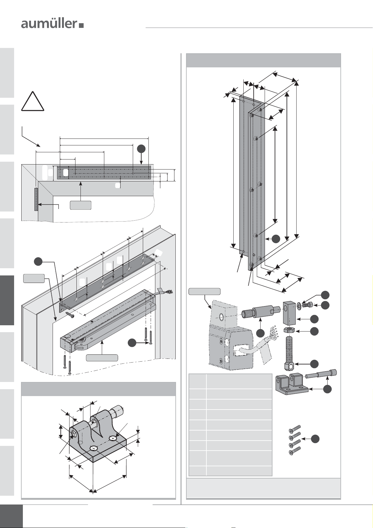
MOUNTING FTA600 R
INSTALLATION STEP 4B:
Screw the angle
of frame bracket K88 at the
FTA600 R - HINGE-SIDE MOUNTING - INWARD OPENING DOOR
door frame (M5).
Fasten folding arm drive FTA600 R on the angle
- with the screws .
Make sure they are parallel to door frame.
!
K88 frame bracket FTA600 R
24
4
50
20,5
40
1x Angle, L = 422
1x Angle, L = 100
1x Angle, L = 100
4x Screw M5 x 45
3x Screw M5 x 12
50 x 40 x 4
50 x 75 x 5
with slots
50 x 75 x 5
Mount angle
upwards
1
Space at the frame:
92 - 106 mm
200
70
330
400
Mount angle
down
1
FTA600 RFTA600 R
Space at the frame:
56 - 70 mm
Mount angle
1
down
05
M5
(x4)
408
Ø
(x8)
5,5
33
4
11
22
260
1
400
2
100
422
75
3x Lock washer
DIN 6797
3
50
X-4
Measure "X": See table on the following page
5
X-4
door frame
BD
330
200
70
reference
edge
400
40
40
7
11
min.16
max.30
min.52
max.66
1
22
11
min.23
max.37
door leaf
Mount angle
upwards
7
22
11
space
56 - 70
space
92 - 106
6
40
28
84
5
door frame
Screw the angle
BD
reference
edge
of frame bracket K88 at the
min.52
max.66
min.63
max.77
door leaf
door leaf (M5).
42
Fasten and adjust the angle
- with screws
and
lock washers .
• for inward and outward opening doors
• on the hinge-side (frame NSK)
• opposite the hinge-side (frame NSK)
Assembly Instruction
16
FTA 600
!
Ensure that the role of the folding arm
drive FTA600 R - when opening and closing is based on the angle
K88!
OUNTING FTA600 R
M
105,5
50
FTA600 R
Mount angle
Mount angle
down
1
FTA600 R
3
upwards
M5
1
40
3
3
M5
door frame
5
6
5050
door frame
5
6
M5
reference
edge
door leaf
M5
75
2
reference
edge
door leaf
min. 78 / max. 117
2
75
Measure depending on the opening angle „α ~90°“, window overlap „FÜ“ and door hinge dimension „B“
X
outside
BD
B
door frame
door leaf
93°
~ 90°
Į
PATTERN A - A
FTA600 R
inside
100
K88
1
Mount angle K88
upwards
K88
2
K88
3
„X“ „B“ „FÜ“
60 mm 13 mm 0 mm
FÜ
55 mm 22 mm 0 mm
45 mm 36 mm 0 mm
70 mm 13 mm 10 mm
60 mm 22 mm 10 mm
45 mm 36 mm 10 mm
Opening angel „α“ ~ 90°
door
3
5050
Ensure that the role of the folding arm drive FTA600 R
- when opening and closing - is based on the angle
!
470
400
330
200
70
FTA600 R
4040
X-4
X
min.52
max.66
3
2
min.63
max.77
door leaf
AA
K88!
24 V DC
Mount angle
upwards
1
FTA600 R
Space
92 - 106
After application of the voltage, the door lock contact is
activated for 10 seconds. With a delay of about 5 seconds, the drive arm of the folding arm drives FTA600 R
starts moving and opens to an angle of max. 93°.
During the closing operation, the door lock contact
is not activated.
40 30
84
100
11
28
8
reference
edge
22
11
42
50
Flow diagram FTA600 R
U
OPEN
0
CLOSE
1
0
OPEN
0
CLOSE
t = 10 s
t = 5 s
View
from inside
t [s]
05
Assembly Instruction
FTA 600
17
MOUNTING FTA600 DF
INSTALLATION STEP 4C: FTA600 DF - HINGE-SIDE - INWARD OPENING SIDE-HING WINDOW
Screw the angle
frame (M5).
Fasten folding arm drive FTA600 DF on the angle
- with the screws .
Make sure they are parallel to casement edge.
!
Measure "X": See table on the following page
05
1
reference
edge
X+4
space
FLRA
46
BD
70
40
reference
70
M4
200
edge
of frame bracket K103 at the
400
330
1
130
22
6
70
130
33
11
408
13
24
9
24
35
FTA600 DF
K103 frame bracket FTA600 DF
50
24
4
20,5
40
422
408
400
260
1
11
(x4)
M5
Ø 5,5 (x8)
22
33
2
6
8
3
7
18
FTA600 DF
RA
M5
Hole layout for F1 casement bracket
9
6
15
Ø6
Assembly Instruction
8
30
FTA 600
Ø6
35
Ø6,5
0
2
4
1x Angle,
6
• for inward opening windows
• on the hinge-side (frame NSK)
L = 422 - 50 x 40 x 4
1x Bolt - ø14 x 57 x M10
1x Lever arm - 14 x 12 x 30
1x Eyebolt M8
1x Casement bracket F1
1x Washer DIN 9021
1x Nut M8
1x Screw M4 x 40
4x Screw M5 x 45
5
9

OUNTING FTA600 DF
36
47
10
40
20
35
25
M
Screw the casement bracket F1
K103 at the frame (M6).
X+4
measure "X":
see table below
RA
BD
FTA600 DF
+ X- X
View without
folding arm drive FTA600 GF
+ X- X
BD
FTA600 DF
RA
measure "X":
X+4
see table below
356 -
386 -
2
mounting
40
10
mounting
2
400
top
down
down
top
140 0
1735
1
K104
7135
400
1
4
- DIN left
- DIN right
- DIN left
- DIN right
4
of frame bracket
6
20
13, 5
5
5
5
20
13, 5
6
1
24
13
reference
edge
F1
reference
edge
13
24
Using the screw and washer - fasten
bolt
and lever arm
on the folding arm drive
FTA600 DF.
Turn the nut
Using the eyebolt
F1
35
with the lever arm.
on the eyebolt.
and connect the casement bracket
Adjust the eyebolt - depending of the window
overlap (FÜ).
2
FTA600 DF
35
3
8 6
7
4
5
B
- X
!
+ X
Note power transmission on
the hinge and frame.
Opening angel „α“ as a function of the door hinge dimension „B“
PATTERN A - A
outside
FÜ
40
inside
FTA600 DF
Į
window
AA
View
from inside
B
B
PATTERN B - B
6
44
46
50
48
FTA600 DF
90
„α“ „X“
84° -35 mm
83° -30 mm
82° -20 mm
81° -15 mm
81° -10 mm
79° 0 mm
77° 10 mm
„B“ = 10 2 mm
Door hinge dimension
Assembly Instruction
FTA 600
76° 20 mm
75° 30 mm
05
K103
43,5
67,5
19
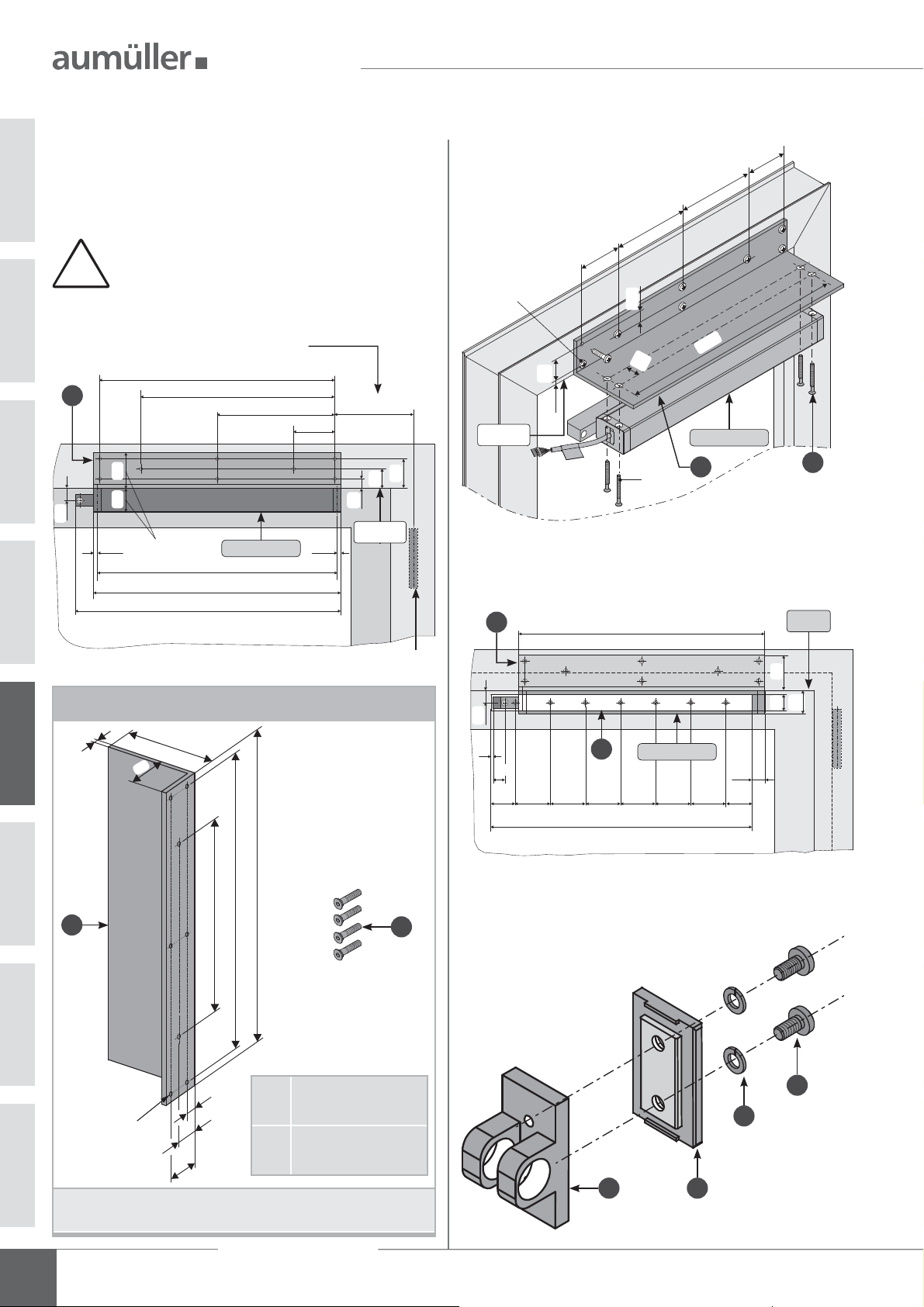
MOUNTING FTA600 GF
INSTALLATION STEP 4D:
Screw the angle
frame (M5).
Fasten folding arm drive FTA600 GF on the angle
- with the screws .
of frame bracket K104 at the
FTA600 GF
OPPOSITE HINGE SIDE MOUNTING
-
- OUTWARD OPENING SIDE-HUNG WINDOW
130
130
70
!
Measure "X": See table on the following page
1
RA
20
Make sure they are parallel to casement edge.
400
330
200
60
40
6,5 6,5
Space
FTA600 GF
408
421
452
70
X+4
33
16
reference
edge
FL
50
BD
M4
reference
edge
RA
Fit slide rail
1
70
17
24
34
16
M5
with screws (M5) at the casement.
422
408
FTA600 GF
1
Bezugs
60
2
kante
-
05
K104 frame bracket FTA600 GF
4
1
Ø5,5 (x8)
• for outward opening windows
• opposite the hinge-side (frame NSK)
60
120
50
33
16
260
400
422
1x Angle, L = 422
120 x 60 x 6
4x Screw M5 x 45
40
20
250
60
45
Using the screws
the slide
3
60 60 60 60 60
FTA600 GF
450
and lock washers and mount
on the connector.
2
45
20
0
FL RA
2
6
7
5
4
20
Assembly Instruction
FTA 600
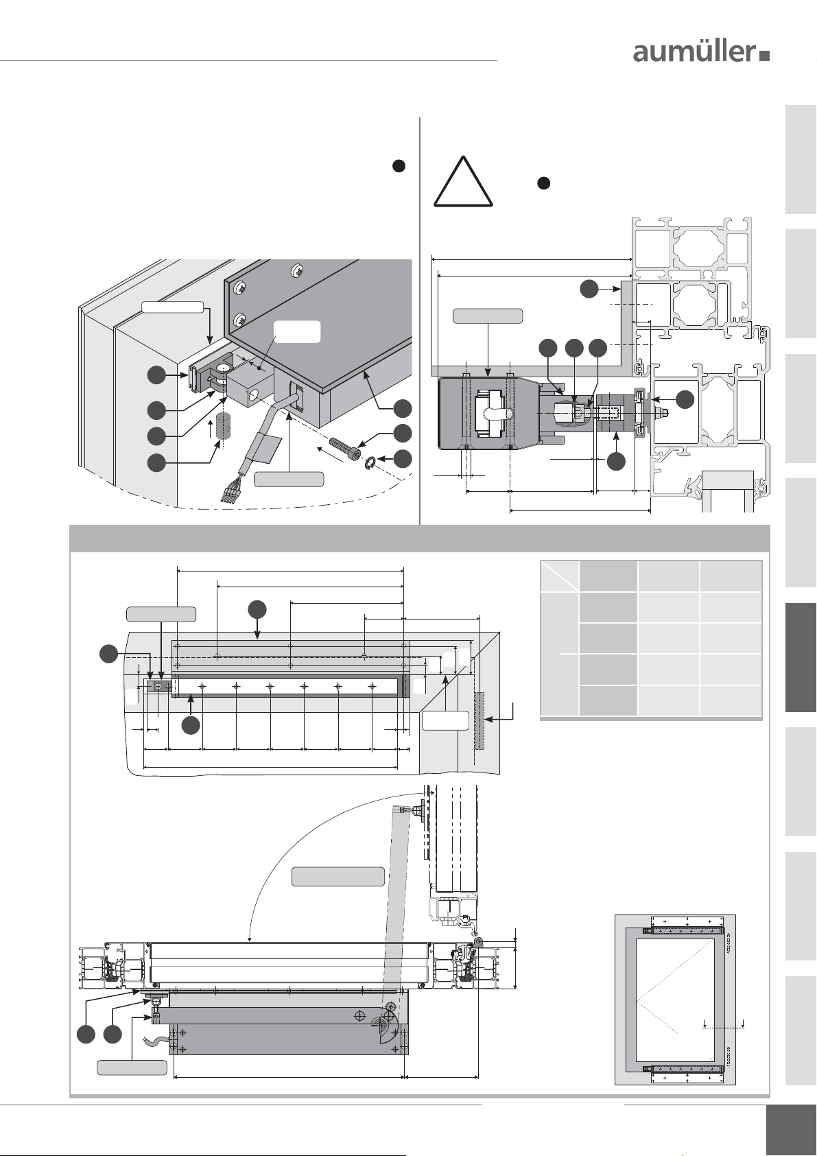
OUNTING FTA600 GF
M
in the connector.
Insert this module
Using the screw
- and mount the drive arm
in slide rail .
of the folding arm drive FTA600 GF - on the bolt.
Keeping a distance of 2 mm.
Screw
must be secured with "Loctite".
Bezugskante
min. 2
3
5
11
8
RA
24 V DC
FTA600 GF
11
10
Insert the circlip
- for stabilization - in the drill hole. Push bolt
Keeping a distance of 2 mm - between drive
11
arm und connector.
!
120
117
1
5
20
10
3
9
FTA600 GF
10
M5
M5
11
9
1
9
ø5,5
24
min. 2
46
min. 77
Opening angel „α“ depending on the pro le depth „PT“ and door hinge dimension „B“
5
FTA600 GF
20
20
5
60
45
1
3
60 60 60 60
450
400
330
200
60
70
45
X+4
60
50
33
16
reference
9
edge
20
BD
Door hinge dimension „B“
„α“ „PT“ „X“
90° 65 mm 115 mm
90° 75 mm 125 mm
0 bis 10 mm
90° 65 mm 125 mm
90° 75 mm 135 mm
10 bis 22 mm
Į
PATTERN A - A
outside
B
PT
05
window
5 3
FTA600 GF
408
inside
X
AA
View
from inside
Assembly Instruction
FTA 600
21

ABLE ROUTING
C
CABLE ROUTING ON THE CASEMENT OR FRAMEINSTALLATION STEP 5:
Cable routing on or in the casement
Cable on the casement
FTA600
cable duct glued on
(in addition secured with
countersunk screws
against breaking away)
Cable routing on the frame
Cable on the frame
RA
AK
cable duct glued on
(in addition secured with countersunk
screws against breaking away)
0706
Connection cable routing on the casement:
• Cable must be protected against damage (shearing-off, kinking,
splitting), i.e. by using bushings.
Upon removal of the glazing bead is the dan-
!
Cable crossover without
protective cable hose
ger that the glass may fall.
Cable crossover with
protective cable hose
FL
RARA FL
Connection cable routing on the frame or transom:
• Cable must be protected against damage (shearing-off, kinking,
splitting), i.e. by using bushings.
protective cable
BDBD AK
hose
Connection cable routing on the hinge side:
• Make sure that during opening or closing procedure the cable will
not be damaged by shearing-off, kinking, crushing.
• Protect cable feedthrough in pro le e.g. by using cable bushings,
cable transitions.
Assembly Instruction
22
FTA 600

ELECTRIC CONNECTION
INSTALLATION STEP 6:
ELECTRIC CONNECTION
Make sure when establishing the connection
that there is no voltage at the terminals!
Unused wires must be safely insulated!
The running direction of the drive may be changed by
interchanging (polarity reversal) the wires „BN – (brown)“
- „BU – (blue)“.
Connection assignment
AK
BN
BU
WH
GN
VT
BN
+
BU
WH is used for communication
(in systems with synchronized
multi-drive operation)
Standard CLOSE / Optional OPEN:
contact max. 24 V, 500 mA
(min. 10mA)
-
-
+
Direction of travel
OPEN
CLOSE
Polarity reversal
+
-
+
-
Wire colour coding
Wire colour coding DIN IEC 757
blake BK
white WH
brown BN
blue BU
green / yellow GN / YE
green GN
violet VT
grey GY
Multi-drive operation with M-COM
WH connection.
Drives do not work, if not connected.
!
drive 1
AK AK
WH
polarity
reversal
+
-
BN
+
-
junction box
site-supplied
WH WH
Optional: Optional:
is used for communication, with synchronized multi-drive
operation.
1 to 4 drives and max. 2 locking drives are possible. 1 to 4 drives and max. 2 locking drives are possible.
+
24 V DC control
from control unit
BU
-
M-COM
drive 2
Multi-drive operation with master and slave
WH connection.
Drives do not work, if not connected.
!
master
AK AK
WH
polarity
BN
+
junction box
site-supplied
The programming of the drives in multi-drive occurs at factory or on
site with UniPC
is used for communication, with synchronized multi-drive
operation.
24 V DC control
from control unit
-
BU
reversal
+
-
+
-
slave
06
Assembly Instruction
FTA 600
23

ELECTRIC CONNECTION
AUMÜLLER-Click plug solution - SITE-SUPPLIED CUSTOMISED CONSTRUCTION
The AUMÜLLER-Click plug solution enabling the use of
site-supplied cable. It simpli es assembly and the electrical
connection of the drives.
2
Loosen the screws
2
Locking hooks - at the housing cover -
NOTE
prevent withdrawal of the plug under tensile
load.
and remove the housing cover .
24 V DC
1
1
24 V DC
3
Replace cable set - provided by the customer in place of
connecting cable.
Moung the housing cover with the both screws .
Five terminals to 1,5 mm2.
The performances (especially the re be-
NOTE
havior) of locally provided cables, must be
checked on own responsability on compliance with the application-speci c local
regulations!
1
Locking hooks
On the underside of the plug housing are two
openings for releasing the locking hooks.
Push locking hook with a screwdriver inwards - and
depress simultaneously.
0706
Openings for releasing the
locking hooks
Push locking hook with a
screwdriver inwards - and
depress simultaneously
3
4
AK
3
Connection assignment
Function Colour DIN IEC 757
OPEN / CLOSE blue BU
OPEN / CLOSE brown BN
Data white WH
Rel: NO violet VT
Rel: NO green GN
24
1
Assembly Instruction
FTA 600

ELECTRIC CONNECTION
M-COM (Main control unit)
Order number:
Application:
Rated voltage:
Current consumption:
Drive type:
Protection class:
Ambient temperature:
Dimensions:
Connecting wires:
Feature / Equipment:
printed circuit board with
connecting wires for integration in site-supplied
junction box.
524177
Main control unit for the automatic
con guration and monitoring of max. 4
opening / 2 locking drives type S12 / S3
(software version SW-V2) in multi-drive
systems.
24V DC +/- 20%, (max. 2 Vss)
<12 mA
S12
IP30 rubber jacket
0 °C ... + 70 °C
45 x 17 x 6 mm
3 wires 0,5 mm² x 50 mm
UniPC with con guration interface
Order number:
Application:
Rated voltage:
Parameterizable
drives:
Scope of delivery:
Features /
Equipment:
Power supply 24V DC
is not included in the
scope of delivery!
Any extended settings
require a software
licence.
524178
Hard- and software for con guration of
drives supplied by AUMÜLLER GmbH
24V DC +/-20%
24V DC type MP, S3, S12, S12 V.2
230V AC type S12, S12 V.2
software UniPC (Downloadlink*), Interface
“ParInt”, USB cable, connection cable
* http://www.aumueller-gmbh.de/Downloads
Cable junction box (for renewal)
Order number:
Application:
Rated voltage:
Material:
Protection class:
Dimensions:
Equipment:
513344
to extend a drive cable
only for „safety extra low voltage“
to max. 50V DC/AC
stainless steel (V2A)
IP 40
25 x 27 x 150 mm
with cable gland (grey)
including strain relief,
with 2 loose ceramic terminals
(bipolar).
5
,
1
2
Ø5
7
2
4
0
c
a
4
.
1
5
0
1
1
0
7
2
1
8
Any recon guration of a drive is entirely at the
user‘s own risk and responsibility.
AUMÜLLER-Click plug solution
Order number:
Application:
Rated voltage:
Connecting cable:
Terminal:
• Flexible cable length
• Connect multiple drives
in series connection
• Torsion-plug
• Locking hooks prevent
5
withdrawal of the plug
under tensile load
• Strain relief according
DIN EN 60335-1 by
screwing the housing
halves
501250 - 1 m cable length - 24 V DC
501258 - 2 m cable length - 24 V DC
501251 - 3 m cable length - 24 V DC
501252 - 5 m cable length - 24 V DC
501253 - 10 m cable length - 24 V DC
Unitary plug-solution for all
UMÜLLER chain drives and
A
AUMÜLLER folding arm drives
24 V DC (± 20 %), max. 2 Vpp
non-halogen, grey 5 x 0,5 mm
2
to 1,5 mm2 - 5 pieces
24 V DC
06
Assembly Instruction
FTA 600
25

ELECTRIC CONNECTION / SAFETY CHECK
INSTALLATION STEP 7:
SUPPLY LINES OF DRIVES TO THE CONTROL UNIT
Observe current regulations and guidelines e.g. DIN 410212 regarding the “Fire behavior of building materialscircuit integrity maintenance of electric cable systems“
(E30, E60, E90) and the “Specimen Guideline on Conduits
German designation - MLAR“, and also prescribed constructional regulations!
RECOMMENDATION
Formula to calculate
the required wire cross-section of a supply line
2
A
mm
=
Available data:
• cut-off current per drive (i. e. 2 x 4.0A) from data sheet
• length to be bridged from the last window to the control unit
(i. e. 10 meters)
(2 * 4,0A) * 10m * 2
A =
2,0V * 56m / (Ω*mm
A = 1,42mm2 -> 1,5mm2 chosen
For safety reasons a cable of the next higher wire cross section should be selected.
24V
IL 2
A m
2,0 56
*
(total)
V
(voltage drop)
(length supply line)
Calculation example
2
)
*
*
m / (Ω*mm
2
)
INSTALLATION STEP 8:
SAFETY CHECK AND TEST RUN
Check the mounted system for its safety; perform test run
and commissioning.
Safety test:
• Connect operating voltage.
• Check fastening (frame brackets, casement brackets)
for rm t or tightening.
Test run:
• Visual inspection of casement movements.
• Stop immediately by malfunction!
• Pay attention to collision with facade construction and
correct installation, if required.
Risk evaluation:
Before operating a power-operated window to which
window drives were mounted, which were sold by the
manufacturer as incomplete machines according to installation declaration, the possible risk to ahazard of persons
must be determined, evaluated and minimized by taking
appropriate technical measures in accordance with the Machinery Directive. Separate documents for performing a risk
assessment can be downloaded from the homepage of
Firm AUMÜLLER Aumatic GmbH
(www.aumueller-gmbh.de).
Laying and connecting the drive cable
• Avoid extreme temperature differences in the instal lation area (danger of condensation).
• Set clamping point close to window and ensure
accessibility.
• Ensure expansion possibilities of the drive and the drive
cable.
• Consider the cable length of drives.
0706
Operation of the power-operated window
When operating the power-operated window safety
instructions must be observed, speci cally those pertaining
to commissioning, operation and maintenance.
26
Assembly Instruction
FTA 600
MAINTENANCE AND REPAIR
HELP IN CASE OF MALFUNCTIONS, REPAIRS AND
AINTENANCE
M
Professional repair of a defect drive can only be performed at the
manufacturer’s factory or manufacturer-certi ed specialist company.
Unauthorized opening or manipulation of the drive terminates warranty.
1. Exchange defect drives or have them repaired by the manufacturer.
2. In case of problems during installation or normal operation the
following table might be useful:
Problem Possible causes Possible solutions
Drive does not
start
Drive doesn‘t
start after
having been
in operation
several times
Drive doesn‘t
close
Drive travels
uncontrolled in
open and close
direction
Door release
contact does not
switch
• Duration of mains
power supply too short
• Drive run direction not
correct
• Connecting cable not
connected
• Power supply / Control
Unit voltage incorrect,
too high or too low (see
data sheet)
• No mains supply to
power supply unit /
Control Unit
(no voltage)
• Drive has shut down
on overload
• Operating time has been
exceeded, drive has
been overheated
• See possible solutions
above associated with
„Drive doesn‘t start“
• Safety mechanism has
been triggered
• See possible solutions
above associated with
„Drive doesn‘t start“
• Residual ripple of power
supply / control unit too
hight
• Fault in power supply
unit / Control Unit
• Contakt defect
• Faulty programming
• Adjust supply voltage
as speci ed in the
technical documentation
• Check drive cables
change polarity
• Check all connection
cables
• Check power supply unit
and replace if necessary
• Connect power supply
• First move drive in
CLOSE direction
• Wait until drive has
cooled down and start
again
• See possible solutions
associated with:
“Drive doesn‘t start“
• Release safety area for
operation and brie y
move the drive in OPEN
direction
• See possible solutions
associated with:
“Drive doesn‘t start”
• Adjust drive voltage to
the required value of
drive. (values see data
sheet of drive)
• Check output voltage of
power supply unit or
Control Unit
• Sending drive for
repair
• Check voltage and
current consumption
of the door opener
• Check programming
with UniPC
MAINTENANCE AND MODIFICATION
To ensure continuous function and safety of the drive periodic maintenance by a specialist company is required at least once a year (as mandated
by law for smoke and heat exhaust systems). Operational readiness must
be checked regularly. Frequent inspection of the system for imbalance
and signs of wear or damages of cables and fastening elements must be
performed.
During maintenance contaminations must be removed from the drive.
Fastenings and clamping screws must be checked for tightness. Test runs
during the opening and closing procedure of the devices must be performed.
The drive itself is maintenance-free. Defect devices may only be repaired
in our factory. Only replacement parts of the manufacturer may be used.
When the connection cable of this device is damaged it must be replaced
by the manufacturer or his customer service or a similarly quali ed person to avoid endangerment.
It is recommended to conclude a maintenance contract. A sample maintenance contract can be downloaded from the homepage of
Firm Aumüller Aumatic GmbH
(www.aumueller-gmbh.de).
While cleaning the windows, drives may not have direct contact with
water or cleaning agents. Drives must be protected from dirt and dust
during the construction phase or renovations.
Maintenance process
1. Open or extend power-operated casement completely.
2. Completely disconnect the system from the mains and secure it
against automatic or manual activation.
3. Check windows and ttings for damages.
4. Check all mechanical fastenings (if required, observe information on
torques in installation instructions).
5. Check electric drives for damages and contaminations.
6. Check connecting cables (drive cable) for:
- tightness of the cable screw
- functionality of the strain relief
- damages
7. Check the mobility of hinges and ttings and re-adjust or apply
lubricant, e.g. silicone spray (observe the instructions of the manu facturer of this window system).
8. Check peripheral seal, remove contaminations or replace.
9. Perform cleaning to maintain functionality (e.g. clean extending
elements of the drive, such as chains or spindles by damp wiping them
with acid or lye-free agents and drying them and, if required, lubricate
them with cleansing oil e.g., Ballistol).
10. Turn on operating voltage.
11. Open and close the power-operated window via the operating
voltage (functional test).
12. If available, check and re-adjust protection systems of the safe guard
xture.
13. Check the intactness of the CE label at the power-operated system
(e.g. SHEV/Natural smoke and heat exhaust ventilators).
14. Check the intactness of warning instructions and labels at the
respective drive.
15. Perform a risk assessment in accordance with Machinery Directive
2006 / 42 / EG, if required, e.g. after modifying the machine.
07
Assembly Instruction
FTA 600
27

DISPOSAL / WARRANTY
WARRANTY AND CUSTOMER SERVICEDEMOUNTING AND DISPOSAL
The drives are demounted by reversing the steps, as for the installation.
The adjustments are omitted.
1. Completely disconnect the system from the power supply before
demounting a drive.
2. After demounting a drive the window must be secured against in dependent opening.
Dispose of parts according to the locally applicable legal provisions.
LIABILITY
We reserve the right to change or discontinue products at any time
without prior notice. Illustrations are subject to change. Although we take
every care to ensure accuracy, we cannot accept liability for the content
of this document.
In principal apply our:
„General Terms for the Supply of Products and Services of the
Electrical Industry (ZVEI)“.
The warranty corresponds with legal provisions and applies to the
country in which the product has been acquired.
The warranty includes material and manufacturing defects incurred
during normal use.
The warranty period for delivered material is twelve months.
Warranty and liability claims for personal injuries or material damages
are excluded, if caused by one or more of the following:
• Improper use of the product.
• Improper installation, commissioning, operation, maintenance or
repair of the product.
• Operating the product by defect and improper installed or not
functioning safety and protection devices.
• Ignoring instructions and installation requirements in these in structions.
• Unauthorized constructional modi cations at the product or
accessories.
• Disaster situations due to effects of foreign bodies and Acts of God.
• Wear and tear.
Point of contact for possible warranty claims or for repair parts or accessories is the responsible branch of ce or the responsible person at
UMÜLLER Aumatic GmbH.
Firm A
Contact data are available at our homepage
(www.aumueller-gmbh.de)
08
28
Assembly Instruction
FTA 600
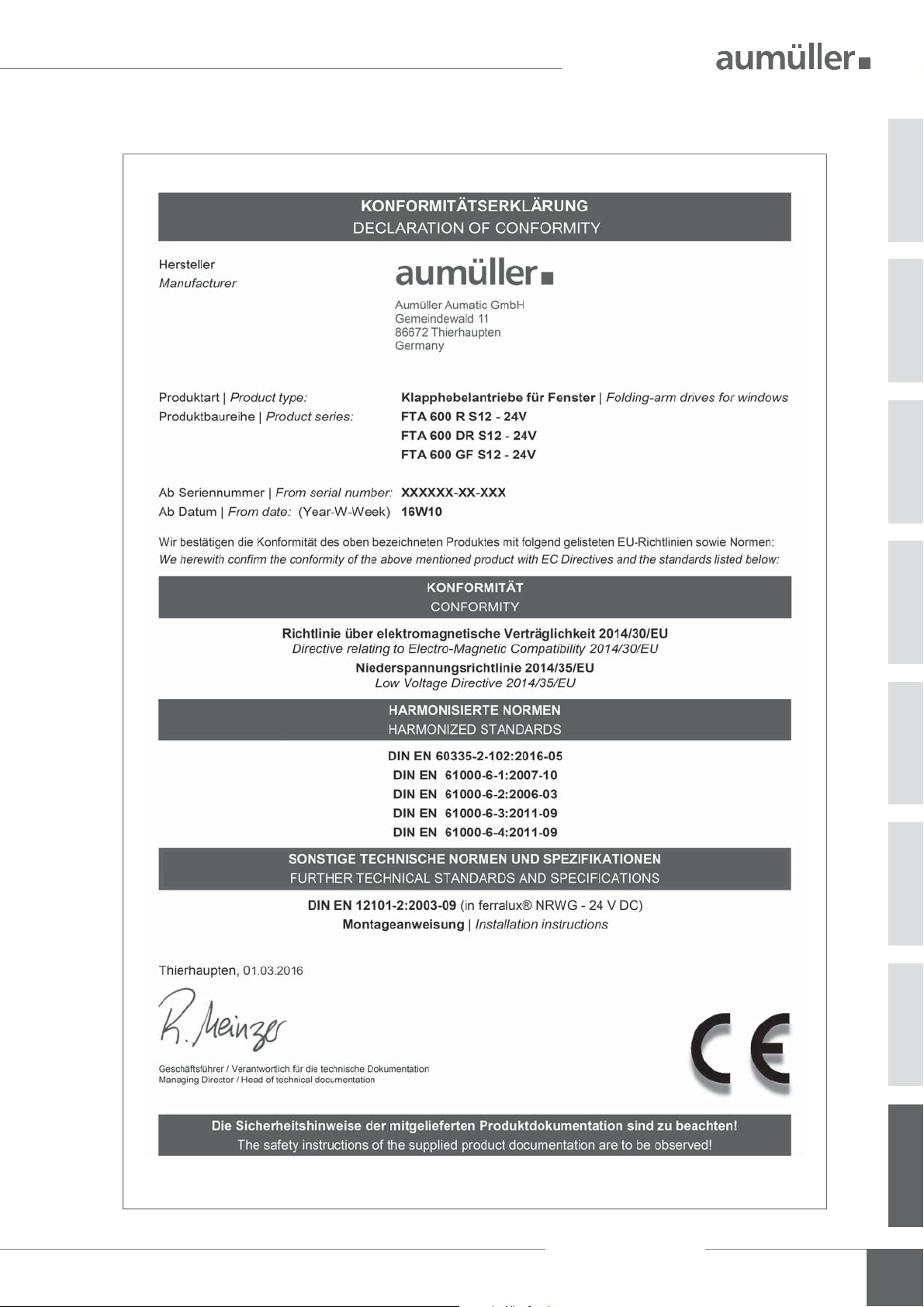
CERTIFICATES
Assembly Instruction
FTA 600
08
29

CERTIFICATES
08
30
Assembly Instruction
FTA 600

TRANSLATION OF THE ORIGINAL INSTRUCTIONS (GERMAN)
Once the assembly and commissioning has been completed, the installer of a machine „power-operated window and door“ shall hand these
instructions over to the end-user. The end-user shall store these instructions in a safe place for further reference and use, if required.
Important note:
We are aware of our responsibility, which is why we present life-supporting and value-preserving products with greatest possible conscientiousness.
Although we make every effort to ensure that the data and information are as correct and up-to-date as possible, we still cannot guarantee that
they are free from mistakes and errors.
All information and data contained in this document are subject to alterations without prior notice. Distribution and reproduction of this document
as well as the use and disclosure of its content is not authorized unless expressly approved. Offenders will be held liable for the payment of damages. All rights reserved in the case of a patent award or utility model registration.
Basically the General Terms and Conditions of Aumüller Automatic GmbH apply to all offers, supplies and services.
The publication of these assembly and commissioning instructions supersedes all previous editions.
Assembly Instruction
FTA 600
08
31

Tel. +49 8271 8185-0
AUMÜLLER AUMATIC GMBH
AUMÜLLER AUMATIC GMBH
Gemeindewald 11
Gemeindewald 11
86672 Thierhaupten
86672 Thierhaupten
Tel. +49 8271 8185-0
Fax
+49 8271 8185-250
Fax
+49 8271 8185-250
info@aumueller-gmbh.de
info@aumueller-gmbh.de
www.aumueller-gmbh.de
9000022501_V1.0_KW25/16
9000017000_V0.1_KW05/14
 Loading...