

Page 1

Multi-turn actuators
SA/SAR 07.2 – 16.2 / SAEx/SAREx 07.2 – 16.2
SAV/SARV 07.2 – 16.2 / SAVEx/SARVEx 07.2 – 16.2
with actuator controls
AC 01.2/ACExC 01.2
ACV 01.2/ACVExC 01.2
SFC version
Functional safetyManual
Page 2

Multi-turn actuators
Table of contents SA .2 with AC(V) 01.2/AC(V)ExC 01.2
NOTICE for use!
This document is only valid with the latest operation instructions attached to the device, the attached manual,
the attached declaration of incorporation as well as the respectively pertaining technical and electrical data sheets.
They are understood as reference documents.
Purpose of the document:
The present documents informs about the actions required for using the device in safety-related systems in
accordance with IEC 61508 or IEC 61511.
Reference documents:
●
exida report no. AUMA 10-12-035 R005E
●
Operation instructions (Assembly, operation, commissioning) for actuator
●
Manual (Operation and setting) actuator controls AC 01.2/ACExC 01.2
●
Manual (Operation and setting) actuator controls ACV 01.2/ACVExC 01.2
●
Manual (Device integration Fieldbus) AC 01.2/ACExC 01.2 / ACV 01.2/ACVExC 01.2
Reference documents are available on the Internet at: http://www.auma.com.
Table of contents Page
104. Safety instrumented systems and safety functions...........................................................
115. Installation, commissioning and operation.........................................................................
115.1. Installation
115.2. Commissioning
115.3. Operation
115.4. Lifetime
125.5. Decommissioning
41. Terminology............................................................................................................................
41.1. Abbreviations and concepts
62. Application and validity.........................................................................................................
62.1. Range of application
62.2. Standards
62.3. Valid device types
73. Architecture, configuration and applications......................................................................
73.1. Architecture (actuator sizing)
73.2. Configuration (setting)
73.3. Protection against uncontrolled operation (self-locking/brake)
83.4. Operation mode (low/high demand mode)
83.5. Further notes and indications on architecture
93.6. Applications (environmental conditions)
136. Tests and maintenance..........................................................................................................
136.1. Safety equipment: check
136.2. Proof test (verification of safe actuator function)
136.2.1. Preliminary tests
136.2.2. Review and validation of the “Safe end position signal” safety function
146.2.3. Checking the collective fault signal
146.3. Partial Valve Stroke Test (PVST)
146.4. Maintenance
2
Page 3

Multi-turn actuators
SA .2 with AC(V) 01.2/AC(V)ExC 01.2 Table of contents
157. Safety-related figures.............................................................................................................
157.1. Determination of the safety-related figures
168. SIL Declaration of Conformity (example).............................................................................
21Index........................................................................................................................................
22Addresses...............................................................................................................................
3
Page 4
Multi-turn actuators
Terminology SA .2 with AC(V) 01.2/AC(V)ExC 01.2
1. Terminology
●
Information sources
1.1. Abbreviations and concepts
IEC 61508-4, Functional safety of electrical/electronic/programmable electronic
safety-related systems – Part 4: Definitions and abbreviations
●
IEC 61511-1, Functional safety - Safety instrumented systems for the process
industry sector – Part 1: Fr amework, definitions, system, hardware and softw are
requirements
To evaluate safety functions, the lambda values or the PFD value (Probability of
Dangerous Failure on Demand) and the SFF value (Safe Failure Fraction) are the
main requirements. Further figures are required to assess the individual components.
These figures are explained in the table below.
Table 1: Abbreviations of safety figures
ation
S
D
DU
DD
PFD
proof
avg
Lambda Dangerous Undetectedλ
Diagnostic CoverageDC
Mean Time Between FailuresMTBF
Safe Failure FractionSFF
Aver age Probability of dangerous Failure on Demand
Hardware Failure ToleranceHFT
DescriptionFull expressionAbbrevi-
Number of safe failuresLambda Safeλ
Number of dangerous failuresLambda Dangerousλ
Number of undetected dangerous fail-
ures
Number of detected dangerous failuresLambda Dangerous Detectedλ
Diagnostic Coverage - ratio between
the failure rate of dangerous failures
detected by diagnostic tests and total
rate of dangerous failures of the component or subsystem.The diagnostic
coverage does not include any f ailures
detected during proof tests.
Mean time between the occurence of
two subsequent failures
Fraction of safe failures as well as of
detectable dangerous failures
Average probability of dangerous failures on demand of a safety function.
Ability of a functional unit to execute a
required function while faults or deviations are present. HFT = n means that
the function can still be safely ex ecuted
for up to n faults occurring at the same
time.
Interval for proof testProof test intervalT
Safety function
Safety instrumented
function (SIF)
Safety instrumented
system (SIS)
Safety-related system
4
Safety Integrity Level
SIL
The international standard IEC 61508 defines 4 levels (SIL 1 through SIL 4).
Function to be implemented by a safety-related system for risk reduction with the
objective to achieve or maintain a safe state for the plant/equipment with respect to
a specific dangerous event.
Function with specified safety integrity level (SIL) to achieve functional safety.
Safety instrumented system for executing a single or several safety instrumented
functions. An SIS consists of sensor(s), logic system and actuator(s).
A safety-related system includes all factors (hardware, software, human factors)
necessary to implement one or several safety functions. Consequently failures of
safety function would result in a significant increase in saf ety risks for people and/or
the environment.
A safety-related system can comprise stand-alone systems dedicated to perform a
particular safety function or can be integrated into a plant.
Page 5

Multi-turn actuators
SA .2 with AC(V) 01.2/AC(V)ExC 01.2 Terminology
Proof test
MTTR (Mean Time To
Restoration)
MRT (Mean Repair Time)
Device type (type A and
type B)
Periodic test performed to detect dangerous hidden f ailures in a safety-related system
so that, if necessary, a repair can restore the system to an "as new" condition or as
close as practical to this condition.
Mean time to restoration once a failure has occurred. Indicates the expected mean
time to achieve restoration of the system. It is therefore an important parameter for
system availability.The time for detecting the failure, planning tasks as well as
operating resources is also included. It should be reduced to a minimum.
Mean repair time indicates the mean time required to repair a system.The MRT is
crucial when defining the reliability and availability of a system.The MRT should
preferably be small.
Actuator controls can be regarded as type A devices if all of the follo wing conditions
are met for all components required to achieve the safety instrumented function:
●
The failure modes for all constituent components involved are well defined
●
The behaviour under fault conditions can be completely determined.
●
There is sufficient dependable failure data from the field to show that the claimed
rates of failure are met (confidence level min. 70 %).
Actuator controls shall be regarded as type B devices if one or sev eral of the follo wing
conditions are met:
●
The failure of at least one constituent component is not well defined.
●
The fault behaviour is not completely known.
●
There is insufficient dependable failure data to support claims for rates of f ailure
for detected and undetected dangerous failures.
PTC (Proof Test Cover-
age)
Proof test coverage describes the fraction of f ailures which can be detected by means
of a proof test.
5
Page 6

Multi-turn actuators
Application and validity SA .2 with AC(V) 01.2/AC(V)ExC 01.2
2. Application and validity
2.1. Range of application
AUMA actuators and actuator controls with the safety functions mentioned in this
manual are intended for operation of industrial valves and are suitable for use in
safety instrumented systems in accordance with IEC 61508 or IEC 61511.
2.2. Standards
Both actuators and actuator controls meet the following requirements:
For safety functions “Safe end position fieedback”: IEC 61508-2:2010
The safety figures of the devices described meet the requirements of IEC 61508 in
the respective SIL level with regard to failure rates and architecture requirements.
However, this does not imply that all further requirements of IEC 61508 are met.
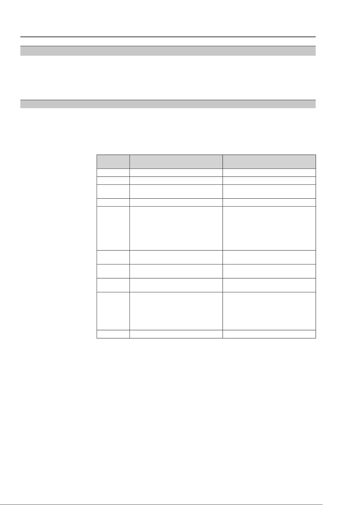
2.3. Valid device types
The data on functional safety contained in this manual applies to the device types
indicated.
Table 2: Overview on suitable device types
Type
Actuator
SA 07.2 – SA 16.2
SAR 07.2 – SAR 16.2
in SFC version
SAEx 07.2 – SAEx 16.2
SAREx 07.2 – SAREx 16.2
in SFC version
SAV/SARV 07.2 – 16.2
SAVEx/SAR VEx 07.2 – 16.2
in SFC version
Information
Type
Actuator controls
in SFC version
in SFC version
in SFC version
Power supply
Any supplyAC 01.2
S2 - 30 min
S4 - 25 %
S4 - 50 %
Any supplyACExC 01.2
S2 - 30 min
S4 - 25 %
S4 - 50 %
Any supplyACV/ACVExC 01.2
S2 - 30 min
S4 - 25 %
S4 - 50 %
ControlType of dutyMotor
Safe end position feedbackS2 - 15 min
Safe end position feedbackS2 - 15 min
Safe end position feedbackS2 - 15 min
Hardware, software and configuration of actuator and actuator controls must not be
modified without prior written consent by AUMA. Unauthorised modification may
have a negative impact on both safety figures and SIL capability of the products.
In applications with requirements on functional safety, only AUMA actuator controls
and actuators in SFC or SIL version may be used. SFC stands for “Safety Figure
Calculated”.This designation identifies AUMA products for which saf ety figures were
calculated on the basis of FMEDA from field data and generic data (for detailed information refer to <Determination of the figures>).
AUMA actuator controls and actuators in SFC v ersion can among others be identified
from the letters "SFC" following the type designation on the name plate.
Figure 1: Example of name plate with “SFC” marking
6
Page 7
Multi-turn actuators
SA .2 with AC(V) 01.2/AC(V)ExC 01.2 Architecture, configuration and applications
3. Architecture, configuration and applications
3.1. Architecture (actuator sizing)
For actuator architecture (actuator sizing) the maximum torques, run torques and
operating times are taken into consideration.
Incorrect actuator architecture can lead to device damage within the safetyrelated system!
Possib le consequences can be valve damage , motor overheating, contactor jamming,
defective thyristors, heating up or damage to cables.
→
The actuator technical data must imperatively be observed when selecting the
actuator.
→
Sufficient reserves have to be provided to ensure that actuators are capab le of
reliably opening or closing the valve even in the event of an accident or undervoltage.
Information
For the “Safe end position feedback” safety function, heed that signalling is made
via mechanical switches. Since these elements have an unav oidab le h ysteresis , the
actuator slightly leaves the end position before the end position signal is deleted.
Consequently, there is a marginal range of actuator positions to the safety position,
for which the end position is still signalled although the actuator has already left the
end position during operation from safety position. If the range in question is approached from the opposite direction, this limitation does not apply. In general this
range is relatively small. However, for unfavourable configurations (low number of
turns per stroke), this range can amount to more than 10 % of the total stroke.
Should, within the framework of unfa v ourab le conditions, the eff ect described abov e
represent an unacceptable limitation for the saf ety function, we recommend ev aluating
both limit and torque switches for the end position feedback.
Power supply
Information
The plant operator is responsible for power supply.
3.2. Configuration (setting)
Configuration (setting) of the safety-related functions is performed as described in
the operation instructions or in the present manual (functional safety).
Information
An exact setting of torque and end position switches f or the end positions is imperatively required to ensure correct function of “Safe end position feedback”. For setting
details related to the respective switches, please refer to operation instructions.
Configuration of reaction monitoring diagnostics and Partial V alve Str oke T est
(PVST)
Depending on the type of diagnostics required, the reaction monitoring or Partial
Valve Stroke Test configurations have to be checked and adapted, if required.
For detailed configuration options on reaction monitoring as well as detailed
information on the Partial Valve Stroke Test (PVST), refer to Manual (Operation and
setting) AUMATIC AC 01.2.
3.3. Protection against uncontrolled operation (self-locking/brake)
For self-locking AUMA actuators, it can be assumed that a load up to maximum
torque will not result in uncontrolled valve operation from standstill due to v alve torque
load. Consequently, in these cases, further protection against uncontrolled operation
is not imperatively required. Howe ver , certain applications may require activ e position
locking, for e xample b y using a brake .There are user-specific standards demanding
this type of protection.Therefore, each project must be subject to individual verification
if any further protection is required. In any case, this protection is required for
actuators without self-locking.
7
Page 8

Multi-turn actuators
Architecture, configuration and applications SA .2 with AC(V) 01.2/AC(V)ExC 01.2
Table 3: Overview self-locking for AUMA actuators (at the time of printing of this document)
Self-lockingOutput speedType
60 Hz50 Hz
Self-locking≤ 108 rpm≤ 90 rpmSA 07.2 – SA 16.2
SAR 07.2 – SAR 16.2
SAEx 07.2 – SAEx 16.2
SAREx 07.2 – SAREx 16.2
SAV 07.2 – SAV 16.2
SARV 07.2 – SARV 16.2
SAVEx 07.2 – SAVEx 16.2
SARVEx 07.2 – SARVEx 16.2
and 12 – 120 1/min
NOT self-locking≥ 150 rpm≥ 125 rpm
Self-lockingSpeed range variants 6 – 60 1/min
NOT self-lockingSpeed range variant 24 – 240 1/min
3.4. Operation mode (low/high demand mode)
The safety functions of the actuators supplied by AUMA are suitable for the low
demand mode and may only be used in this operation mode. If a non-safety
instrumented function of basic process control system is executed via the same
actuator in addition to the safety function, note that while considering the sum of
non-safety instrumented function, required tests and safety function, the defined
number of maximum permissible cycles1) for the respective actuator as well as the
maximum number of starts2) may not be exceeded during deplo yment of the actuator
within a safety instrumented system.
Only the “safe end position feedback” safety function can be operated beyond
the limitations mentioned above under certain conditions even in operation mode
with high demand rate, provided the following requirements and limitations are
heeded:
●
When considering the sum consisting of non-safety instrumented function, required tests and safety function, the number of maximum cycles of the actuator
end position switches as well as the maximum number of starts during actuator
deployment are not exceeded in a safety instrumented system.
●
When considering the sum consisting of non-safety instrumented function, required tests and safety function, the number of maximum cycles f or the respective actuator as well as the maximum number of permissible cycles1) or starts
are not exceeded, if appropriate scaling rules are applied.
●
Lubrication is checked at regular intervals and the lubricant changed if required,
however, at least every 10 years.
●
Every 20,000 cycles1) or starts2) (whatever occurs earlier), the crown wheel and
the worm wheel are checked for wear and replaced if required.
●
The end user makes sure that a test rate (PVST) is achieved for the “Saf e end
position feedback” safety function, complying with the demand r ate to be expected according to the applicable standards for the respective application.
●
All requirements in accordance with the “Technical data for switches” (Y004.619)
data sheet are respected. In particular , the permissible minimum and maximum
currents and voltages.
●
The number of cycles1) as well as the number of cycles of each limit and torque
switch do not exceed the values stipulated in the table below:
2)
Table 4:
switch as well as cycles according to EN 157142:2010
3.5. Further notes and indications on architecture
HFT is 0.
Only flanges of F07 or FA 07 sizes or larger may be used for valve attachment.
1) Definition of “cycles” according to EN 15714-2:2010
2) Definition of “starts” according to DIN EN 15714-2:2010
8
Class C (Modulation)Classes A and B
GoldGoldSilverSilverGoldSilverContact material
50 V/400 mA30 V/30 mA250 V AC/5 A30 V/30 mAMaximum electrical load
< 20,000< 100,000< 20,000< 100,000< 20,000< 20,000Number of permissible cycles of end position
Page 9

Multi-turn actuators
SA .2 with AC(V) 01.2/AC(V)ExC 01.2 Architecture, configuration and applications
For “safe end position feedback”, the actuator can be considered as type A device.
Safety figures
The safety figures relevant for the product supplied as well as potential further
restrictions are indicated on the declaration of incorporation.The declaration of
incorporation is specific for each order and directly supplied with the order.
3.6. Applications (environmental conditions)
When specifying and using the actuators within safety instrumented systems, make
sure that the permissible service conditions and the EMC requirements by the
peripheral devices are met. Service conditions are indicated in the technical data
sheets:
●
Enclosure protection
●
Corrosion protection
●
Ambient temperature
●
Vibration resistance
If the actual ambient temperatures exceed an av erage of +40 °C , the lambda v alues
have to be incremented by a safety factor. For an average temperature of +60 °C,
this factor is specified to 2.5.
For environmental test, actuator and actuator controls were subjected to the f ollowing
standards:
●
Dry heat: EN 60068-2-2
●
Damp heat: EN 60068-2-30
●
Cold: EN 60068-2-1
●
Vibration test: IEC 60068-2-6
●
Induced seismic vibration (earthquake): IEC 68-3-3
●
Enclosure protection test IP68: EN 60529
●
Salt spray test: EN ISO 12944-6
●
Immunity requirements: EN 61326-3-1
●
Emission: EN 61000-6-4
3)
3) Thyristor version only
9
Page 10

Multi-turn actuators
Safety instrumented systems and safety functions SA .2 with AC(V) 01.2/AC(V)ExC 01.2
4. Safety instrumented systems and safety functions
In calculating the safety figures of the actuator, the following safety functions are
taken into account:
●
Safe end position feedback
An end position signal directly wired to the actuator is available.The safety
function is the correct signal whether the actuator is in the requested actuator
end position or not. Only the signal via this signal comm unication path is safety
related. End position feedback via I/O interface relay or a positioner (RWG,
MWG, potentiometer, ...) or via a fieldbus interface does not represent a safe
end position feedback.
4)
4) Please note that safety figures only include the components of the actuator . Further components (e.g.
integrity of external controls, gearboxes , valve shaft, other valve components....) are not considered with
the AUMA safety figures related to this product
Page 11

Multi-turn actuators
SA .2 with AC(V) 01.2/AC(V)ExC 01.2 Installation, commissioning and operation
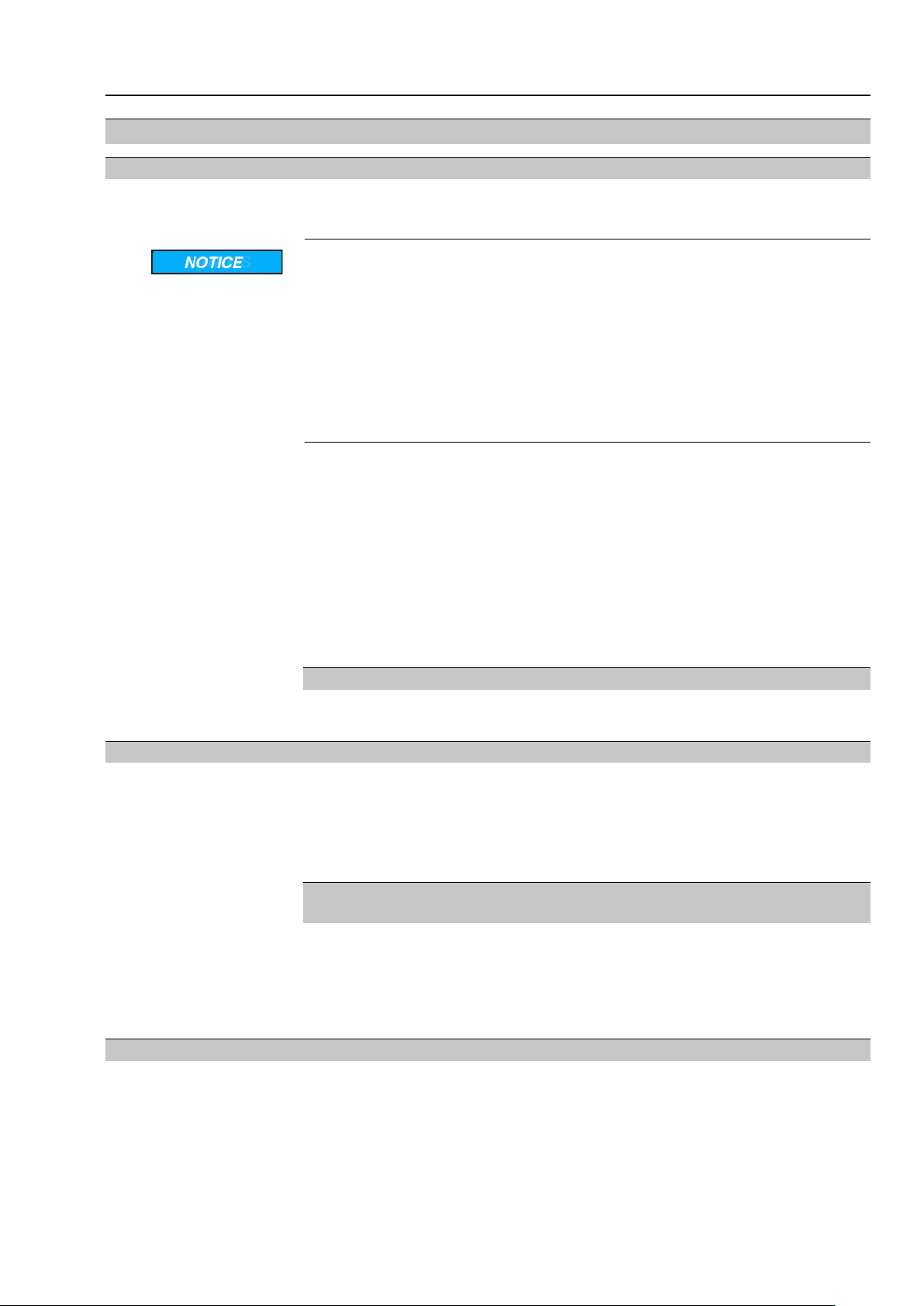
5. Installation, commissioning and operation
Information
5.1. Installation
Installation and commissioning have to be documented by means of an assembly
report and an inspection certificate. Installation and commissioning may only be
performed by authorised personnel who have been trained on functional safety.
General installation tasks (assembly, electrical connection) have to be performed
according to the operation instructions pertaining to the device and the enclosed
order-specific wiring diagram.
Figure 2:Wiring diagram example with safe end position feedback
[1] Limit switches for safe end position feedback
Information
5.2. Commissioning
5.3. Operation
Installation and commissioning must be recorded and a final installation and
commissioning report must be issued.
When connecting actuator controls to safety PLC and a functional control system,
make sure that the inputs and outputs used have separate potentials. Imperatively
avoid one common f or inputs and outputs when connecting to circuit of safety system
and basic process control system. Particular attention to comply with these
requirements has to be paid when selecting the input for the ESD signal, the inputs
and outputs of PVST and for fault signals (and possibly other feedback signals).
Valve position indication is made via potentiometer or 4 – 20 mA signals. However,
this is not part of the determination of safety figures.
The operation instructions pertaining to the device must be observed for general
commissioning.
After commissioning, the safe actuator function must be verified.
Regular maintenance and device checks in the T
intervals as defined by the
proof
plant operator are the basis for safe operation.
The operation instructions pertaining to the device must be observed for operation.
The plant operator is responsible for power supply.
Once a fault occurs, the system has to be checked immediately and the installation
has to be put in a safe state, if required.
5.4. Lifetime
Actuator lifetime is described in the technical data sheets or the operation instructions.
Safety-related figures are valid for the cycles or modulating steps defined in the
technical data specifications and for typical periods of up to 10 years (the criterion
achieved first is valid). After this period, the probability of failure increases.
11
Page 12

Multi-turn actuators
Installation, commissioning and operation SA .2 with AC(V) 01.2/AC(V)ExC 01.2
Extending this period is basically feasible in many cases “provided both manuf acturer
and operator introduce respective actions” in compliance with footnote N3 of NOTE
3 of the German version of IEC 61508-2:2010 7.4.9.5 b).This is the responsibility
of the operator who will have to take appropriate and suitable measures. Please
contact us if you need support in identifying suitable measures.
5.5. Decommissioning
When decommissioning an actuator with safety functions, the following must be
observed:
●
Impact of decommissioning on relevant de vices, equipment or other w ork must
be evaluated.
●
Safety and warning instructions contained in the actuator operation instructions
must be met.
●
Decommissioning must be carried out exclusively b y suitably qualified personnel.
●
Decommissioning must be recorded in compliance with regular requirements.
12
Page 13

Multi-turn actuators
SA .2 with AC(V) 01.2/AC(V)ExC 01.2 Tests and maintenance
6. Tests and maintenance
Test and maintenance tasks may only be performed by authorised personnel who
have been trained on functional safety.
Test and maintenance equipment has to be calibrated.
Information
Any test/maintenance must be recorded in a test/maintenance report.
Impact of testing/maintenance on relevant devices, equipment or other work must
be evaluated.
6.1. Safety equipment: check
All safety functions within a safety equipment m ust be checked f or perfect functionality
and safety at appropriate intervals.The intervals for saf ety equipment checks are to
be defined by the plant operator.
The plant operator has to establish a safety schedule for the entire safety lifecycle
of the SIS to avoid systematic faults. Policies and strategies for achieving safety as
well as different activities during the safety life cycle should be defined.
6.2. Proof test (verification of safe actuator function)
The proof test serves the purpose to verify the safety-related functions of the actuator
and actuator controls.
Proof tests shall reveal dangerous f aults which might remain undetected until a safety
function is started and consequently result in a potential danger.
For checking the safety-related function, the output of safe end position feedback is
appropriately checked.
Information All installed and used safety functions within the actuator must be checked and all
test steps performed in compliance with the pertaining checklists.
Intervals:
A proof test interval describes the time between two proof tests. Functionality must
be checked at appropriate intervals.The intervals are to be defined by the plant
operator.
In any case, the safety-related functions must be checked after commissioning and
following any maintenance w ork or repair as well as during the T
in safety assessment.
intervals defined
proof
6.2.1. Preliminary tests
The actuator system has to be subjected to a visual inspection first.The system
should be checked for outside damage and corrosion. Furthermore, the electrical
and mechanical connections should be checked and the actuator inspected for
unusual noises while operating the actuator at least a complete trav el from CLOSED
to OPEN and back.
6.2.2. Review and validation of the “Safe end position signal” safety function Test sequence (check-
list)
1. Operate actuator to end position OPEN – Is the end position OPEN signalled
via Safe end position signal?
2. Unseat actuator out of end position OPEN – Is the safe end position signal
OPEN cancelled?
3. Operate actuator again to end position OPEN – Is the end position OPEN signalled again via Safe end position signal?
4. Operate actuator to end position CLOSED – Is the end position CLOSED signalled via Safe end position signal?
5. Unseat actuator out of end position CLOSED – Is the safe end position signal
CLOSED cancelled?
6. Operate actuator again to end position CLOSED – Is the end position CLOSED
signalled again via Safe end position signal?
13
Page 14

Multi-turn actuators
Tests and maintenance SA .2 with AC(V) 01.2/AC(V)ExC 01.2
7. During the complete procedure, no fault signal at collective fault signal output
contact K1?
6.2.3. Checking the collective fault signal Configuration
Test procedure
Test sequence
This check is applicable for all safety functions.
Checking if collective fault signal correctly indicates the fault.
●
Separately check collective fault signal (K1) by simulating a fault.
- Does the output contact react to the simulated fault?
- Does the output contact react to the cancellation of the simulated fault?
●
Cancel the fault simulation after checking is complete.
6.3. Partial Valve Stroke Test (PVST)
— Option —
During the Partial Valve Stroke Test (PVST), the function of the valve is tested by
means of partial OPENING or CLOSING within a defined period of time without
interrupting the process. After successful testing, actuator controls operate the
actuator to its initial position.
PVST is used to test the function of actuator controls and actuators not operated on
a regular basis and can therefore not use reaction monitoring for diagnostics.
Diagnostic via PVST should be performed at least 10 times more often than the proof
test.
Monitoring and assessment of PVST must be ensured by the logic unit of the safety
instrumented system. For this, the collective fault signal must be assessed.
Safety function for safe end position feedback:
●
Actuator movement can be requested via any input.
●
Assessment whether the safety function signals as desired has to be performed
at the end position switches wired directly to the customer connection.
●
The actuator must be in one of the following positions:
- In one of both end positions prior to starting the test run.
The test run is performed out of the end position and back to this end position.
- At a sufficient distance from both end positions prior to starting the test
run.
The test run is performed into an end position and out of this end position.
In both cases, the travel distance must be sufficient to allow for full tripping of the
end position switch. It must be checked whether the end position switch signals the
expected position both at the beginning, during and at the end of the test.
●
Furthermore, test run monitoring must be dynamic.This means a dynamic test
whether the signal change corresponds to the expected value.
Information
If the PVST is only executed in one of both end positions , only the s witch of this end
position is tested for correct function. If both end position switches (OPEN/CLOSE)
are safety relevant, a full stroke test can be performed, for example.
6.4. Maintenance
14
Maintenance and service tasks may only be performed by authorised personnel who
have been trained on functional safety (refer to chapter 5).
Once maintenance and service tasks have been finished, the functional test must
be completed by a validating process of the safety function including at least the
tests described in the <Safety equipment: check> and <Proof test (verification of
safe actuator function)> chapters.
In case a fault is detected during maintenance, this must be reported to AUMA Riester
GmbH & Co. KG.
Page 15

Multi-turn actuators
SA .2 with AC(V) 01.2/AC(V)ExC 01.2 Safety-related figures
7. Safety-related figures
7.1. Determination of the safety-related figures
●
The calculation of the safety figures is based on the indicated safety functions .
Hardware assessments are based on Failure Modes, Effects and Diagnostic
Analysis (FMEDA). FMEDA is a step to assess functional device safety in
compliance with IEC 61508. On the basis of FMEDA, the failure rates and the
fraction of safe failures of a device are determined.
●
Experience data and data taken from the exida database for mechanical components is used to calculate mechanical failure rates.The electronic failure
rates as base failure rates are taken from the SIEMENS Standard SN 29500.
●
In compliance with table 2 of IEC 61508-1, the average target PFD value for
systems with low demand mode are:
-
SIL 1 safety functions:≥ 10-2 to < 10
-
SIL 2 safety functions:≥ 10-3 to < 10
-
SIL 3 safety functions:≥ 10-4 to < 10
Since actuators only represent a part of the overall safety function, the actuator
PFD value should not account for more than 25 % of the permissible total v alue
(PFD
-
●
Safe end position feedback via end position switches directly wired via the
) of a safety function.This results in the following values:
avg
Actuator PFD for SIL 1 applications:≲ 2.50E-02
customer input can be classified as type A components with hardware fault
tolerance of 0.The SFF for the type A subsystem should be <60 % according
to table 2 of IEC 61508-2 for SIL 1 (subsystems with a hardware f ault tolerance
of 0).The SFF for the type A subsystem should be between 60 % and <90 %
according to table 2 of IEC 61508-2 for SIL 2 (subsystems with a hardware f ault
tolerance of 0).
●
The calculation of the PFD values is based on the following assumptions:
- MRT = 72 hours
- Td = 730 hours = time interval PVST
- MTTR = MRT + Td = 802 hours.
-1
-2
-3
The PFD values specified in the declarations of incorporation and in this safety
manual are only examples and subject to certain assumptions e.g. on T
proof
, MTTR,
… The PFD calculation should always be performed individually for each system
using the parameters and conditions applicable for the respective system.The λ
DU
and λDD values should be used as input.When observing the proof test procedures
indicated in this safety manual, we recommend calculation using proof test cov erage
(PTC) of 90 %.5).
As previously mentioned in the architecture section, safeguarding po wer supply and
resulting calculations are the responsibility of the plant operator.
The plant operator is responsible for eliminating faults within the MTTR, otherwise
the data of the quantitative results is no longer valid.
The safety figures mentioned in this safety manual and in the declarations of
incorporation are only valid if all the conditions stipulated in this safety
manual and in the declarations of incorporation and the mentioned activities
are respected. At the same time, the restrictions regarding the validity and
standard conformity stipulated in the declarations of incorporation must be
heeded.
5) For the example calculations within this manual and the declarations of incorporation, different PTC
values were sometimes used as calculation basis.
15
Page 16

Multi-turn actuators
SIL Declaration of Conformity (example) SA .2 with AC(V) 01.2/AC(V)ExC 01.2
8. SIL Declaration of Conformity (example)
16
Page 17

Multi-turn actuators
SA .2 with AC(V) 01.2/AC(V)ExC 01.2 SIL Declaration of Conformity (example)
17
Page 18

Multi-turn actuators
SIL Declaration of Conformity (example) SA .2 with AC(V) 01.2/AC(V)ExC 01.2
18
Page 19

Multi-turn actuators
SA .2 with AC(V) 01.2/AC(V)ExC 01.2
19
Page 20

Multi-turn actuators
SA .2 with AC(V) 01.2/AC(V)ExC 01.2
20
Page 21

Multi-turn actuators
SA .2 with AC(V) 01.2/AC(V)ExC 01.2 Index
S
Index
A
Actuator sizing 7
Ambient conditions 9
Architecture 7
B
Brake 7
Safe failure fraction (SFF) 4
Safety function 4
Safety functions 10
Safety instrumented function
(SIF)
Safety instrumented system
(SIS)
Safety-related system 4
Self-locking 7
C
Commissioning 11
Configuration 7
Service conditions 9
Setting 7
SFF 4
SIL 4
D
Standards 6
DC 4
Declaration of Conformity 16
Decommissioning 12
Device types 6
T
Tests 13
T proof 4
Diagnostic coverage (DC) 4
F
Figures, safety-related 15
4
4
H
HFT 4
I
Installation 11
Interval for proof test 4
L
Lambda values 4
Lifetime 11
Low Demand Mode 15
M
Maintenance 14
Mean Time Between F ailures
(MTBF)
MRT (Mean Repair Time) 5
MTBF 4
MTTR (Mean Time To Restoration)
O
Operation 11
Operation mode 8
P
Partial Valve Stroke Test
14
(PVST)
PFD 4
PFD for actuator 15
Power supply 7
Probability of failure 4, 11
Proof test 5, 13, 13
4
5
R
Range of application 6
21
Page 22

AUMA worldwide
Europe
AUMA Riester GmbH & Co. KG
Location Muellheim
DE 79373 Muellheim
Tel +49 7631 809 - 0
info@auma.com
www.auma.com
Location Ostfildern-Nellingen
DE 73747 Ostfildern
Tel +49 711 34803 - 0
riester@auma.com
Service-Center Bayern
DE 85386 Eching
Tel +49 81 65 9017- 0
Service.SCB@auma.com
Service-Center Köln
DE 50858 Köln
Tel +49 2234 2037 - 900
Service@sck.auma.com
Service Center Magdeburg
DE 39167 Niederndodeleben
Tel +49 39204 759 - 0
Service@scm.auma.com
AUMA-Armaturenantriebe Ges.m.b.H.
AT 2512 Tribuswinkel
Tel +43 2252 82540
office@auma.at
www.auma.at
AUMA BENELUX B.V. B. A.
BE 8800 Roeselare
Tel +32 51 24 24 80
office@auma.be
www.auma.nl
ProStream Group Ltd.
BG 1632 Sofia
Tel +359 2 9179-337
valtchev@prostream.bg
www.prostream.bg
OOO “Dunkan-Privod”
BY 220004 Minsk
Tel +375 29 6945574
belarus@auma.ru
www.zatvor.by
AUMA (Schweiz) AG
CH 8965 Berikon
Tel +41 566 400945
RettichP.ch@auma.com
AUMA Servopohony spol. s.r.o.
CZ 250 01 Brandýs n.L.-St.Boleslav
Tel +420 326 396 993
auma-s@auma.cz
www.auma.cz
IBEROPLAN S.A.
ES 28027 Madrid
Tel +34 91 3717130
iberoplan@iberoplan.com
AUMA Finland Oy
FI 02230 Espoo
Tel +358 9 5840 22
auma@auma.fi
www.auma.fi
AUMA France S.A.R.L.
FR 95157 Taverny Cedex
Tel +33 1 39327272
info@auma.fr
www.auma.fr
AUMA ACTUATORS Ltd.
GB Clevedon, North Somerset BS21 6TH
Tel +44 1275 871141
mail@auma.co.uk
www.auma.co.uk
D. G. Bellos & Co. O.E.
GR 13673 Acharnai, Athens
Tel +30 210 2409485
info@dgbellos.gr
APIS CENTAR d. o. o.
HR 10437 Bestovje
Tel +385 1 6531 485
auma@apis-centar.com
www.apis-centar.com
Fabo Kereskedelmi és Szolgáltató Kft.
HU 8800 Nagykanizsa
Tel +36 93/324-666
auma@fabo.hu
www.fabo.hu
Falkinn HF
IS 108 Reykjavik
Tel +00354 540 7000
os@falkinn.is
www.falkinn.is
AUMA ITALIANA S.r.l. a socio unico
IT 20023 Cerro Maggiore (MI)
Tel +39 0331 51351
info@auma.it
www.auma.it
AUMA BENELUX B.V.
LU Leiden (NL)
Tel +31 71 581 40 40
office@auma.nl
NB Engineering Services
MT ZBR 08 Zabbar
Tel + 356 2169 2647
nikibel@onvol.net
AUMA BENELUX B.V.
NL 2314 XT Leiden
Tel +31 71 581 40 40
office@auma.nl
www.auma.nl
SIGUM A. S.
NO 1338 Sandvika
Tel +47 67572600
post@sifag.no
AUMA Polska Sp. z o.o.
PL 41-219 Sosnowiec
Tel +48 32 783 52 00
biuro@auma.com.pl
www.auma.com.pl
AUMA-LUSA Representative Office, Lda.
PT 2730-033 Barcarena
Tel +351 211 307 100
geral@aumalusa.pt
SAUTECH
RO 011783 Bucuresti
Tel +40 372 303982
office@sautech.ro
OOO PRIWODY AUMA
RU 141402 Khimki, Moscow region
Tel +7 495 221 64 28
aumarussia@auma.ru
www.auma.ru
OOO PRIWODY AUMA
RU 125362 Moscow
Tel +7 495 787 78 21
aumarussia@auma.ru
www.auma.ru
AUMA Scandinavia AB
SE 20039 Malmö
Tel +46 40 311550
info.scandinavia@auma.com
www.auma.se
ELSO-b, s.r.o.
SK 94901 Nitra
Tel +421 905/336-926
office@elsob.sk
www.elsob.sk
Auma Endüstri Kontrol Sistemleri Limited
Sirketi
TR 06810 Ankara
Tel +90 312 217 32 88
info@auma.com.tr
AUMA Technology Automations Ltd
UA 02099 Kiev
Tel +38 044 586-53-03
auma-tech@aumatech.com.ua
Africa
Solution Technique Contrôle Commande
DZ Bir Mourad Rais, Algiers
Tel +213 21 56 42 09/18
stcco@wissal.dz
A.T.E.C.
EG Cairo
Tel +20 2 23599680 - 23590861
contactus@atec-eg.com
SAMIREG
MA 203000 Casablanca
Tel +212 5 22 40 09 65
samireg@menara.ma
MANZ INCORPORATED LTD.
NG Port Harcourt
Tel +234-84-462741
mail@manzincorporated.com
www.manzincorporated.com
AUMA South Africa (Pty) Ltd.
ZA 1560 Springs
Tel +27 11 3632880
aumasa@mweb.co.za
22
Page 23

AUMA worldwide
America
AUMA Argentina Rep.Office
AR Buenos Aires
Tel +54 11 4737 9026
contacto@aumaargentina.com.ar
AUMA Automação do Brazil ltda.
BR Sao Paulo
Tel +55 11 4612-3477
contato@auma-br.com
TROY-ONTOR Inc.
CA L4N 8X1 Barrie, Ontario
Tel +1 705 721-8246
troy-ontor@troy-ontor.ca
AUMA Chile Representative Office
CL 7870163 Santiago
Tel +56 2 2821 4108
claudio.bizama@auma.com
B & C Biosciences Ltda.
CO Bogotá D.C.
Tel +57 1 349 0475
proyectos@bycenlinea.com
www.bycenlinea.com
AUMA Región Andina & Centroamérica
EC Quito
Tel +593 2 245 4614
auma@auma-ac.com
www.auma.com
Corsusa International S.A.C.
PE Miraflores - Lima
Tel +511444-1200 / 0044 / 2321
corsusa@corsusa.com
www.corsusa.com
Control Technologies Limited
TT Marabella,Trinidad,W.I.
Tel + 1 868 658 1744/5011
www.ctltech.com
AUMA Actuators (China) Co., Ltd.
CN 215499 Taicang
Tel +86 512 3302 6900
mailbox@auma-china.com
www.auma-china.com
PERFECT CONTROLS Ltd.
HK Tsuen Wan, Kowloon
Tel +852 2493 7726
joeip@perfectcontrols.com.hk
PT. Carakamas Inti Alam
ID 11460 Jakarta
Tel +62 215607952-55
auma-jkt@indo.net.id
AUMA INDIA PRIVATE LIMITED.
IN 560 058 Bangalore
Tel +91 80 2839 4656
info@auma.co.in
www.auma.co.in
ITG - Iranians Torque Generator
IR 13998-34411 Teheran
+982144545654
info@itg-co.ir
Trans-Jordan Electro Mechanical Supplies
JO 11133 Amman
Tel +962 - 6 - 5332020
Info@transjordan.net
AUMA JAPAN Co., Ltd.
JP 211-0016 Kawasaki-shi, Kanagawa
Tel +81-(0)44-863-8371
mailbox@auma.co.jp
www.auma.co.jp
DW Controls Co., Ltd.
KR 153-702 Gasan-dong, GeumChun-Gu,,
Seoul
Tel +82 2 2624 3400
import@actuatorbank.com
www.actuatorbank.com
FLOWTORK TECHNOLOGIES
CORPORATION
PH 1550 Mandaluyong City
Tel +63 2 532 4058
flowtork@pldtdsl.net
M & C Group of Companies
PK 54000 Cavalry Ground, Lahore Cantt
Tel +92 42 3665 0542, +92 42 3668 0118
sales@mcss.com.pk
www.mcss.com.pk
Petrogulf W.L.L
QA Doha
Tel +974 44350151
pgulf@qatar.net.qa
AUMA Saudi Arabia Support Office
SA 31952 Al Khobar
Tel + 966 5 5359 6025
Vinod.Fernandes@auma.com
AUMA ACTUATORS (Singapore) Pte Ltd.
SG 569551 Singapore
Tel +65 6 4818750
sales@auma.com.sg
www.auma.com.sg
NETWORK ENGINEERING
SY Homs
+963 31 231 571
eyad3@scs-net.org
Sunny Valves and Intertrade Corp. Ltd.
TH 10120 Yannawa, Bangkok
Tel +66 2 2400656
mainbox@sunnyvalves.co.th
www.sunnyvalves.co.th
Top Advance Enterprises Ltd.
TW Jhonghe City,Taipei Hsien (235)
Tel +886 2 2225 1718
support@auma-taiwan.com.tw
www.auma-taiwan.com.tw
AUMA ACTUATORS INC.
US PA 15317 Canonsburg
Tel +1 724-743-2862
mailbox@auma-usa.com
www.auma-usa.com
Suplibarca
VE Maracaibo, Estado, Zulia
Tel +58 261 7 555 667
suplibarca@intercable.net.ve
Asia
AUMA Actuators UAE Support Office
AE 287 Abu Dhabi
Tel +971 26338688
Nagaraj.Shetty@auma.com
AUMA Actuators Middle East
BH 152 68 Salmabad
Tel +97 3 17896585
salesme@auma.com
Mikuni (B) Sdn. Bhd.
BN KA1189 Kuala Belait
Tel + 673 3331269 / 3331272
mikuni@brunet.bn
Al-Arfaj Engineering Co WLL
KW 22004 Salmiyah
Tel +965-24817448
info@arfajengg.com
www.arfajengg.com
TOO “Armaturny Center”
KZ 060005 Atyrau
Tel +7 7122 454 602
armacentre@bk.ru
Network Engineering
LB 4501 7401 JBEIL, Beirut
Tel +961 9 944080
nabil.ibrahim@networkenglb.com
www.networkenglb.com
AUMA Malaysia Office
MY 70300 Seremban, Negeri Sembilan
Tel +606 633 1988
sales@auma.com.my
Mustafa Sultan Science & Industry Co LLC
OM Ruwi
Tel +968 24 636036
r-negi@mustafasultan.com
AUMA Vietnam Hanoi RO
VN Hanoi
+84 4 37822115
chiennguyen@auma.com.vn
Australia
BARRON GJM Pty. Ltd.
AU NSW 1570 Artarmon
Tel +61 2 8437 4300
info@barron.com.au
www.barron.com.au
23
Page 24

AUMA Riester GmbH & Co. KG
P.O. Box 1362
DE 79373 Muellheim
Tel +49 7631 809 - 0
Fax +49 7631 809 - 1250
info@auma.com
www.auma.com
For detailed information on AUMA products, refer to the Internet: www.auma.com
Y006.646/003/en/2.19
 Loading...