

AUKS ACWCSC-1180A5/MS, ACWCSC-1570A5/MS, ACWCSC-1380A5/MS, ACWCSC-1080A5/MS, ACWCSC-1880A5/MS Technical Manual
...Page 1
Flooded Type Water Cooled Screw Chiller Technical Manual
Flooded Type Water Cooled Screw Chiller
Technical Manual
Central Air Conditioniner
Page 2
Flooded Type Water Cooled Screw Chiller Technical Manual
Contents
Chapter I Product Selection .................................................................................................................... 1
1. General .............................................................................................................................................. 1
1.1 Product Overview ......................................................................................................................... 1
1.2 Naming Rule ................................................................................................................................ 3
1.3 Function ....................................................................................................................................... 4
2. Unit Performance ................................................................................................................................................. 5
2.1 Performance Parameter Table ...................................................................................................... 5
2.2 Performance Parameter Table on Variable Working Condition ................................................... 9
3. Unit Outline Dimension ........................................................................................................................ 17
Chapter II Installation and Commissioning .............................................................................................. 19
1 Preparation and Tools before Installation ..................................................................................... 19
1.1 Preparation before Installation .................................................................................................... 19
1.2 Tools to be Prepared .................................................................................................................. 20
2 Installation of Unit .......................................................................................................................... 20
3 Connection of Water Pipeline ........................................................................................................ 22
3.1 Basic Requirements of Pipeline Connection ............................................................................. 22
3.2 Pipeline Connection of Condenser ............................................................................................ 23
3.3 Pipeline Connection of Evaporator ............................................................................................ 24
4 Electrical Wiring............................................................................................................................. 26
4.1 Requirements for Power Supply ................................................................................................. 26
4.2 Wiring Requirements .................................................................................................................. 27
5 Commissioning of Unit .................................................................................................................. 28
5.1 Preparation before Commissioning ........................................................................................... 28
5.2 Operation of Unit ........................................................................................................................ 30
Chapter III Operation and Maintenance .................................................................................................. 32
1. Operation Instruction ........................................................................................................................... 32
1.1 Button Instruction of Wired Controller ........................................................................................ 32
1.2 Operation Instruction of Wired Controller .................................................................................. 33
1.2.1 Setting of Parameter ............................................................................................................... 33
1.2.2 Instruction of Main Screen ....................................................................................................... 33
2. Maintenance ........................................................................................................................................ 42
2.1 Daily Maintenance ...................................................................................................................... 42
2.2 Regular Maintenance ................................................................................................................. 43
Chapter IV After-sales Service ................................................................................................................ 46
1. Main Parts of Unit ................................................................................................................................ 46
1.1 Main Pats of Cooling System ..................................................................................................... 46
1.2 Main Parts of Electrical System .................................................................................................. 49
2. Function and Control of Unit ................................................................................................................ 50
2.1 Function and Control of Unit ....................................................................................................... 50
2.2 Loading/Unloading Process Control of Unit ............................................................................... 51
2.3 Protection Function .................................................................................................................... 51
3. Failure Analysis and Solution .............................................................................................................. 55
3.1 Analysis and Solution of Failure with Failure Code ................................................................... 55
3.2 Analysis and Solution of Failure without Failure Code .............................................................. 63
Page 3

Flooded Type Water Cooled Screw Chiller Technical Manual
4. Failure Detection of Electrical Parts..................................................................................................... 66
5. Schematic Diagram of System and Electrical Schematic Diagram ..................................................... 67
6. Exploded Chart and Bill of Material ..................................................................................................... 69
Page 4

Flooded Type Water Cooled Screw Chiller Technical Manual
1
Chapter I Product Selection
1. General
1.1 Product Overview
Flooded-type water-cooled screw chiller unit has characteristics such as high efficiency ratio, compact
structure, beautiful shape, convenient operation and simple cooling system. The unit can be put into
operation immediately after simple installation, water and electricity connection, with improved
operating reliability, safety and economical efficiency of system.
Applicable places:
It is applicable to shopping mall, hospital, hotel, factory, office building, etc.
Product Characteristics:
Flooded-type dedicated compressor:
Adopted semi-hermetic twin-screw compressor and 5:6 unsymmetrical serrated structure which
realize high compression efficiency, 10% energy saving and stable operation;
Since oil level switch is above oil level, it is easy to maintain and repair;
Air suction filter has characteristics of high precision (25μm), large area and less pressure drop,
ensuring best filtering effect;
Oil filter has characteristics of high precision (10μm), large area and less pressure drop, which can
be used and set with maintenance and replacement;
Dual-layer casting wall structure effectively reduces operation noise;
Depressurized bearing housing design reduces content of refrigerant in lubricating oil entering into
bearing and can greatly prolong service life of bearing;
Screw of compressor has compact structure and low length/diameter ratio, which is hard to deform
and more efficient;
Flooded-type shell and tube heat exchanger:
Tailor-made refrigerant distributor makes temperature field of heat exchanger distribute more
evenly. Its total heat transfer coefficient is more than three times of traditional dry evaporator, so it
can transfer heat at low temperature difference, effectively improve cooling capacity and
energy/efficiency ratio of unit and save operating cost;
Chilled water flows in pipe at turbulent flow and is difficult to scale. Removable end plate is easy to
clean and service;
Wide range of cooling capacity:
Wide range of cooling capacity, which can meet different places’ requirement.
Two types: common energy efficiency and high energy efficiency can meet different demands of
users.
More reliable oil-return system:
It uses high-efficiency technology for separating oil two times to minimize oil displacement of
compressor.
Page 5

Flooded Type Water Cooled Screw Chiller Technical Manual
2
It uses high-pressure injection oil return technology to ensure reliable oil-return in all working
conditions.
Accurate matching and higher energy efficiency:
Compressor provides stepless energy adjustment, which can accurately match with actual working
condition and save more energy;
Twin-compressor has parallel connection design and high seasonal energy efficiency;
Intelligent control system:
Visual Operation Control. The set information such as operating status, setting parameter and
failure alarm can reflect to controller and make easier operation and more comprehensible;
Balance control function. Unit automatically adjusts operation time of each system according to
operation status of compressor, which ensures roughly the same operation time of each system,
achieves balanced operation among multiple systems and ensures overall operation stability of
unit.
Unit can select manually or automatically ON/OFF at specified time which bring great convenience
to users. Unit can completely record the last twenty alarm records and occurrence time, providing
detailed information for after-sales maintenance;
It has complete protection function including over high pressure protection, less low pressure
protection, overload protection of compressor, superheat protection of coil, phase lost and reversal
protection, high/low voltage protection, oil level protection, high discharge temperature protection
of compressor, oil pressure difference protection of compressor, chilled water and cooling water
flow protection, overload protection of cooling tower fan and protection function for external linkage.
Multiple protection functions ensure reliable protection of unit at the first time in case of
abnormality and ensure safety of unit;
Optional remote network control function. It can be connected with communication interface of
computer or modulator through RS-485 protocol and easily connected to BAS of standard
industrial bus and public telecom switch network to monitor remote communication;
Page 6

Flooded Type Water Cooled Screw Chiller Technical Manual
3
1.2 Naming Rule
Example:
ACWCSC-1180A5/MS indicates flooded-type water-cooled screw chiller unit with common energy efficiency,
one twin-screw compressor and nominal cooling capacity approximate to 345kW.
Design Revision No.: A, B, C and others follow by analog
Code of refrigerant type: code of R22 is omitted;
code of R407C is “R”;
code of R134a is “R3”;
Serial number of energy efficiency: “G” refers to unit model of high
energy efficiency and serial number of common energy efficiency is
omitted
Quantity of compressor: S stands for single compressor; D stands for
dual-compressor;
Type of evaporator: “M” refers to flooded type;
Nominal cooling capacity: figure×103 W
Cooling type of condenser: “S” refers to water-cooled type;
Code of mode: no indication for single cooling;
Type of compressor: SLG-twin-screw type
Code of cooling water unit: LS
Page 7
Flooded Type Water Cooled Screw Chiller Technical Manual
4
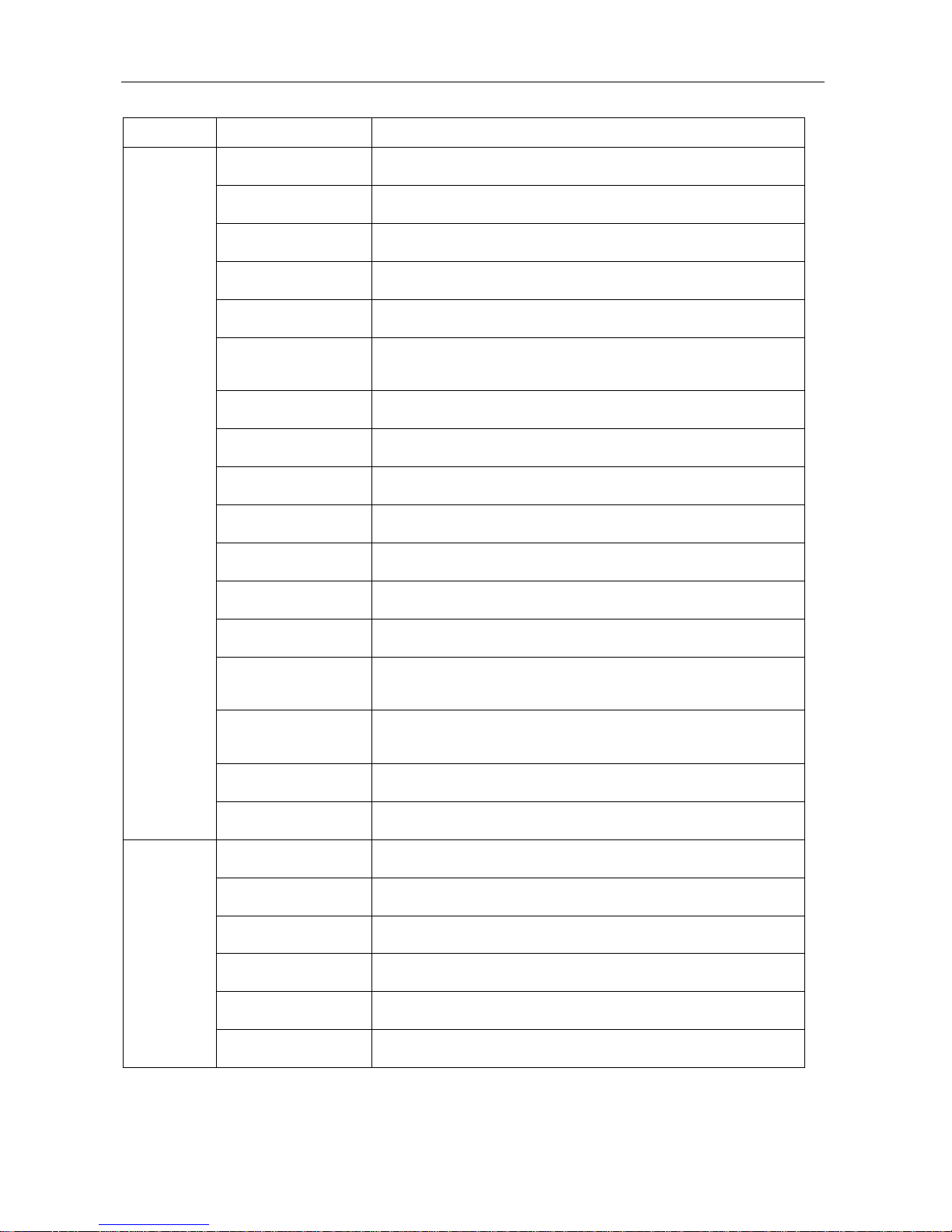
1.3 Function
Item Fuction Name Description
Protection
function
high pressure
protection
shutdown when high pressure exceeds set value
low pressure protection shutdown when low pressure is lower than set value
Compressor overload
protection
shutdown when operating current of compressor exceeds max
operating current
superheat protection of
compressor winding
shutdown when winding of compressor motor exceeds a certain
temperature
high discharge
temperature protection
Shutdown when discharge temperature exceeds setting value
phase sequence
protection (phase lost
and reversal)
shutdown in case of phase lost or reversal
Excessive voltage and
less voltage protection
shutdown when input voltage is morer or les than set high voltage and
low voltage value
high and low voltage
difference protection
shutdown when the difference between high voltage and low voltage is
lower than setting value
Oil pressure difference
protection
shutdown when front and rear pressure difference of oil filter of
compressor exceed set value
oil level protection of
compressor
shutdown under when oil level of compressor is too low
anti-freezing protection shutdown when temperature is too low
failure protection of
temperature sensor
shutdown in case of temperature sensor failure
failure protection of
pressure sensor
shutdown in case of pressure sensor failure
temperature difference
protection when back
water flow
shutdown when temperature difference of cooling water exceeds set
value
temperature difference
protection when
excessive water flow
shutdown when temperature difference of cooling water is lower than
setting value
flow protection of chilled
water pump
protect in case of chilled water flow lacking
flow protection of
cooling water pump
protect in case of I cooling water flow lacking
Operation
function
clock display display year, month, day and time
timing ON/OFF function Set timing ON/OFF function
operating parameter
display
display inlet & outlet temperature and high & low pressure of chilled
water and cooling water
protection information
inquiry
display and inquire protection information
automatic load and
unload
automatically load and unload according to actual requirement
water temperature set Set water temperature within a certain range (10℃~15℃)
Page 8
Flooded Type Water Cooled Screw Chiller Technical Manual
5
2. Unit Performance
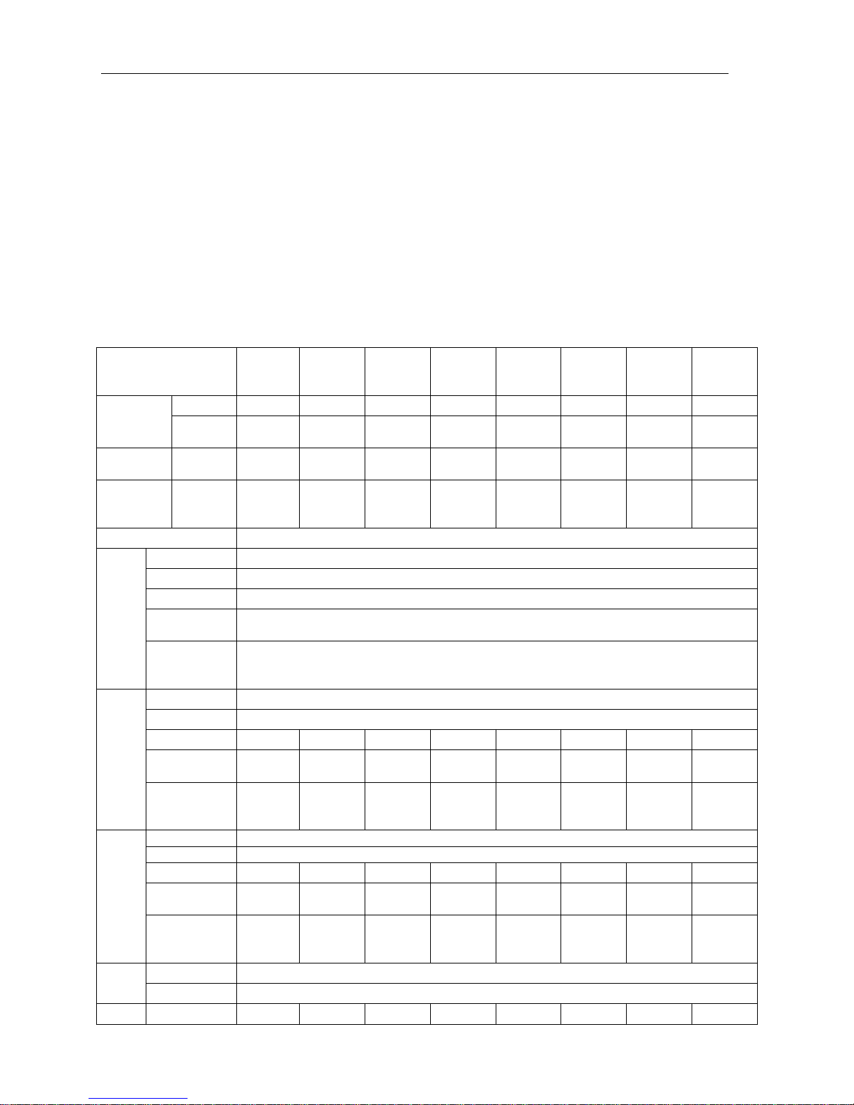
2.1 Performance Parameter Table
Note of performance parameters:
1. Nominal cooling capacity of unit is tested under following working conditions:
Chilled water Inlet temperature: 12 ℃ Outlet temperature: 7℃
Cooling water Inlet temperature of: 30℃ Outlet temperature: 35℃
Fouling coefficient of evaporator: 0.0176m2. /W ℃
Fouling coefficient of condenser: 0.043m2. /W℃
2. Noise is tested at a distance 1m front and 1.5m high of the unit. Ambient noise is lower than
30dB(A);
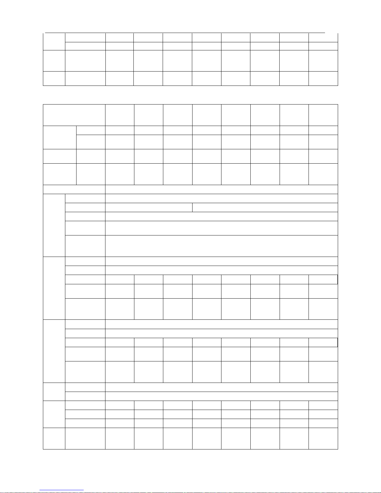
2.1.1 Performance Parameter Table of Unit with Common Energy Efficiency
Model
ACWCS
C-960A5
/MS
ACWCS
C-1080A
5/MS
ACWCS
C-1180A
5/MS
ACWCS
C-1380A
5/MS
ACWCS
C-1570A
5/MS
ACWCS
C-1740A
5/MS
ACWCS
C-1880A
5/MS
ACWCS
C-2120A
5/MS
Cooling
capacity
kW 280 315 340 405 460 510 550 620
kcal/h×10
3
241 271 297 348 396 439 473 533
Cooling
power
kW 57.5 64.8 70.5 82.7 92.0 101.8 108.6 122.2
Max.
running
current
A 171 193 220 241 310 336 355 377
Power supply 380V3N~/50Hz
Compr
essor
Model semi-hermetic screw-type
Quantity (pcs) 1
Startup mode Y-△, shunt winding
Power of oil
heater (W)
300
Adjustment of
cooling
capacity
stepless adjustment
Evapo
rator
Type flooded-type evaporator
Quantity 1
Pipe diameter DN100 DN100 DN125 DN125 DN125 DN125 DN150 DN150
Cooling water
flow (m3/h)
48.2 54.2 59.3 69.6 79.1 87.7 94.6 106.6
Hydraulic
resistance
(Kpa)
44 52 55 56 57 59 59 60
Conde
nser
Type shell and tube condenser
Quantity 1
Pipe diameter DN100 DN100 DN125 DN125 DN125 DN125 DN150 DN150
Cooling water
flow (m3/h)
58.0 65.3 71.5 83.9 94.9 105.2 113.3 127.6
Hydraulic
resistance
(Kpa)
50 54 57 58 59 61 61 62
Refrig
erant
Type R22
Control mode electronic expansion valve
Unit L(mm) 3200 3200 3250 3250 3250 3500 3500 3550
Page 9
Flooded Type Water Cooled Screw Chiller Technical Manual
6
dimen
sion
W (mm) 1150 1150 1150 1200 1200 1200 1300 1350
H (mm) 1500 1500 1500 1630 1670 1670 1700 1700
Opera
ting
noise
dB(A) 74 74 75 76 78 78 79 79
Unit
weight
kg 1700 1830 2000 2450 2550 2850 2900 3050
Continued
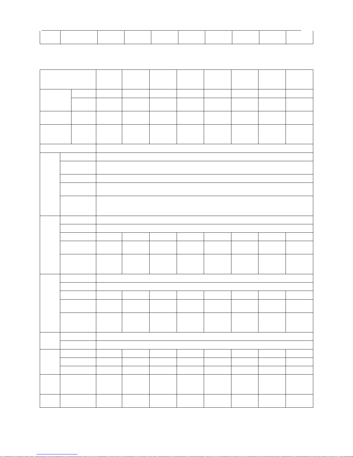
Model
ACWCS
C-2425A
5/MS
ACWCS
C-2730A
5/MS
ACWCS
C-3070A
5/MS
ACWCS
C-3480A
5/MD
ACWCS
C-4200A
5/MD
ACWCS
C-4845A
5/MD
ACWCS
C-5460A
5/MD
ACWCS
C-6140A
5/MD
Cooling
capacity
kW 710 800 900 1020 1230 1420 1600 1800
kcal/h×1
03
610 688 774 877 1058 1221 1376 1548
Cooling
power
kW 140.0 157.1 181.7 200.0 240.3 283.5 312.6 351.1
Max.
running
current
A 453 498 534 672 786 906 996 1068
Power supply 380V3N~/50Hz
Compr
essor
Model semi-hermetic screw-type
Quantity (pcs) 1 2
Startup mode Y-△, shunt winding
Power of oil
heater (W)
300
Adjustment of
cooling
capacity
stepless adjustment
Evapo
rator
Type flooded-type evaporator
Quantity 1
Pipe diameter DN150 DN150 DN150 DN200 DN200 DN250 DN250 DN250
Cooling water
flow (m3/h)
122.1 137.6 154.8 175.4 211.5 244.2 275.2 309.5
Hydraulic
resistance
(Kpa)
64 66 68 70 73 75 76 78
Conde
nser
Type shell and tube condenser
Quantity 1
Pipe diameter DN150 DN150 DN200 DN200 DN200 DN250 DN250 DN250
Cooling water
flow (m3/h)
146.2 164.6 186.0 209.8 252.8 292.9 328.9 369.9
Hydraulic
resistance
(Kpa)
66 68 70 72 75 77 78 80
Refrig
erant
Type R22
Control mode electronic expansion valve
Unit
dimen
sion
L(mm) 3550 3550 3550 4120 4180 4680 4680 4680
W (mm) 1350 1400 1400 1400 1400 1550 1550 1700
H (mm) 1850 1850 1960 2050 2050 2100 2100 2100
Opera
ting
noise
dB(A) 81 82 82 82 82 83 83 83
Page 10
Flooded Type Water Cooled Screw Chiller Technical Manual
7
Unit
weight
kg 3850 4300 4600 5250 6900 7500 8100 9000
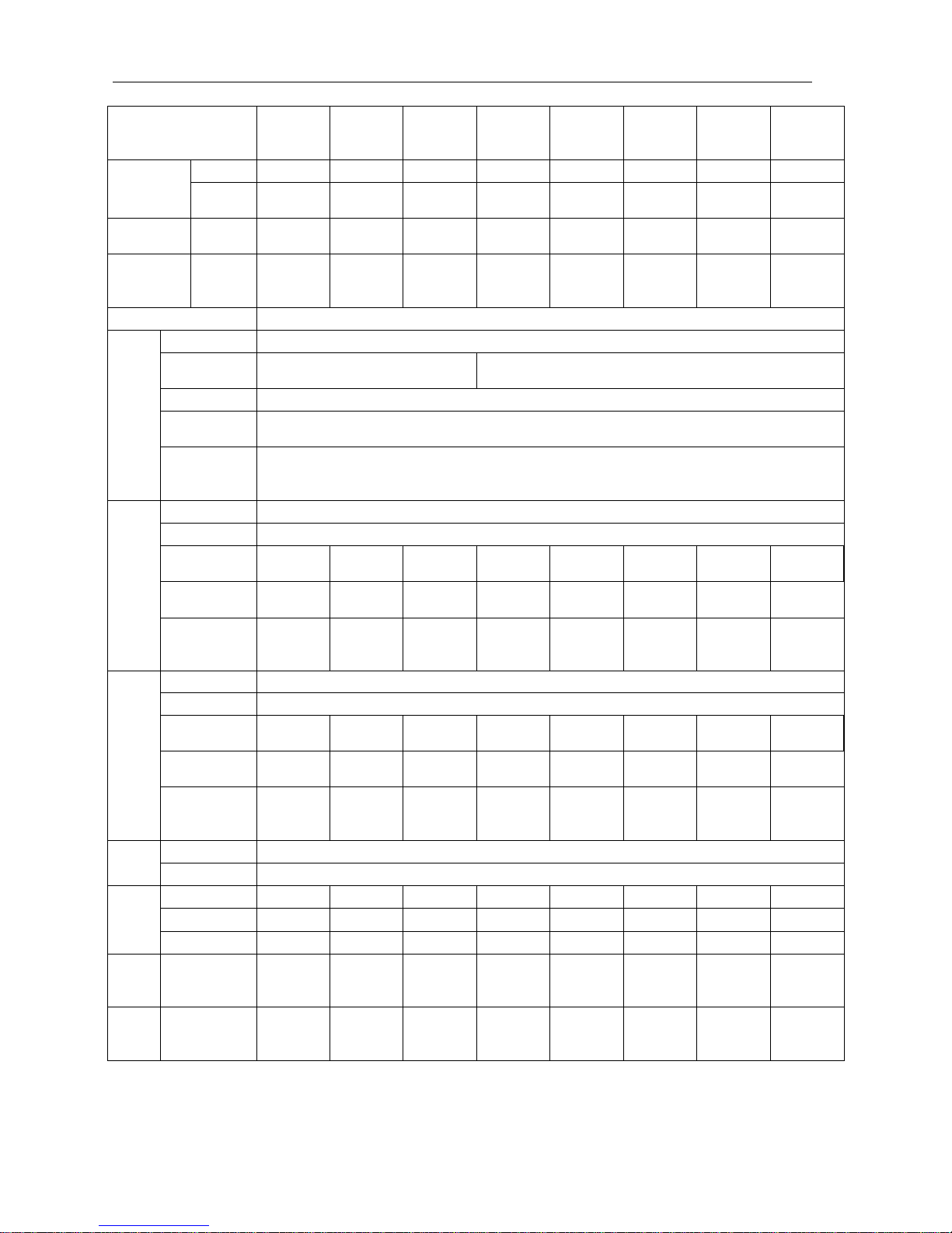
2.2.2 Performance Parameter Table of Unit with High Energy Efficiency
Model
ACWCS
C-960A5
/MSG
ACWCS
C-1080A
5/MSG
ACWCS
C-1180A
5/MSG
ACWCS
C-1380A
5/MSG
ACWCS
C-1570A
5/MSG
ACWCS
C-1740A
5/MSG
ACWCS
C-1880A
5/MSG
ACWCS
C-2120A
5/MSG
Cooling
capacity
kW 280 315 340 405 460 510 550 620
kcal/h×1
03
241 271 297 348 396 439 473 533
Cooling
power
kW 52.2 58.9 64.1 75.1 83.6 92.6 98.7 111.1
Max.
running
current
A 171 193 203 241 268 310 336 355
Power supply 380V3N~/50Hz
Comp
ressor
Model semi-hermetic screw-type
Quantity
(pcs)
1
Startup mode Y-△
Power of oil
heater (W)
300
Adjustment of
cooling
capacity
stepless adjustment
Evapo
rator
Type flooded-type evaporator
Quantity 1
Pipe diameter DN100 DN100 DN125 DN125 DN125 DN125 DN150 DN150
Cooling water
flow (m3/h)
48.2 54.2 59.3 69.6 79.1 87.7 94.6 106.6
Hydraulic
resistance
(Kpa)
44 52 55 56 57 59 59 60
Conde
nser
Type shell and tube condenser
Quantity 1
Pipe diameter DN100 DN100 DN125 DN125 DN125 DN125 DN150 DN150
Cooling water
flow (m3/h)
57.1 64.3 70.4 82.6 93.5 103.6 111.6 125.7
Hydraulic
resistance
(Kpa)
50 54 57 58 59 61 61 62
Refrig
erant
Type R22
Control mode electronic expansion valve
Unit
dimen
sion
L(mm) 3200 3200 3250 3250 3250 3250 3500 3550
W (mm) 1150 1150 1150 1200 1200 1200 1300 1350
H (mm) 1500 1500 1500 1630 1670 1670 1700 1700
Opera
ting
noise
dB(A) 74 74 75 76 78 78 79 79
Unit
weight
kg 1750 1900 2100 2550 2700 2850 3000 3200
Page 11
Flooded Type Water Cooled Screw Chiller Technical Manual
8
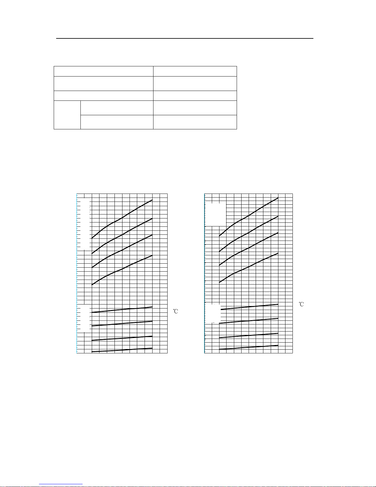
Continued
Model
ACWCS
C-2425A
5/MSG
ACWCS
C-2730A
5/MSG
ACWCS
C-3070A
5/MSG
ACWCS
C-3480A
5/MDG
ACWCS
C-4200A
5/MDG
ACWCS
C-4845A
5/MDG
ACWCS
C-5460A
5/MDG
ACWCS
C-6140A
5/MDG
Cooling
capacity
kW 710 800 900 1020 1230 1420 1600 1800
kcal/h×1
03
610 688 774 877 1058 1221 1376 1548
Cooling
power
kW 127.2 142.9 165.1 181.8 218.5 257.7 284.2 319.1
Max.
operating
current
A 393 453 498 620 672 786 906 996
Power supply 380V3N~/50Hz
Comp
ressor
Model semi-hermetic screw-type
Quantity
(pcs)
1 2
Startup mode Y-△
Power of oil
heater (W)
300
Adjustment of
cooling
capacity
stepless adjustment
Evap
orator
Type flooded-type evaporator
Quantity 1
Pipe
diameter
DN150 DN150 DN150 DN200 DN200 DN250 DN250 DN250
Cooling water
flow (m3/h)
122.1 137.6 154.8 175.4 211.5 244.2 275.2 309.5
Hydraulic
resistance
(Kpa)
64 66 68 70 73 75 76 78
Cond
enser
Type shell and tube condenser
Quantity 1
Pipe
diameter
DN150 DN150 DN200 DN200 DN200 DN250 DN250 DN250
Cooling water
flow (m3/h)
144.0 162.1 183.2 206.7 249.1 288.5 324.0 364.4
Hydraulic
resistance
(Kpa)
66 68 70 72 75 77 78 80
Refrig
erant
Type R22
Control mode electronic expansion valve
Unit
dimen
sion
L(mm) 3550 3550 3550 4120 4180 4180 4680 4680
W (mm) 1350 1400 1400 1400 1400 1550 1550 1700
H (mm) 1850 1850 1960 2050 2050 2100 2100 2100
Opera
ting
noise
dB(A) 81 82 82 82 82 83 83 83
Unit
weigh
t
kg 4000 4500 4800 5400 7100 7800 8400 9300
Page 12
Flooded Type Water Cooled Screw Chiller Technical M
anual
9
2.2 Performance Parameter Table on Variable Working Condition
2.2.1 Operating Range
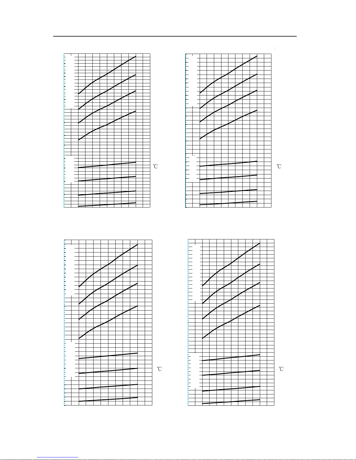
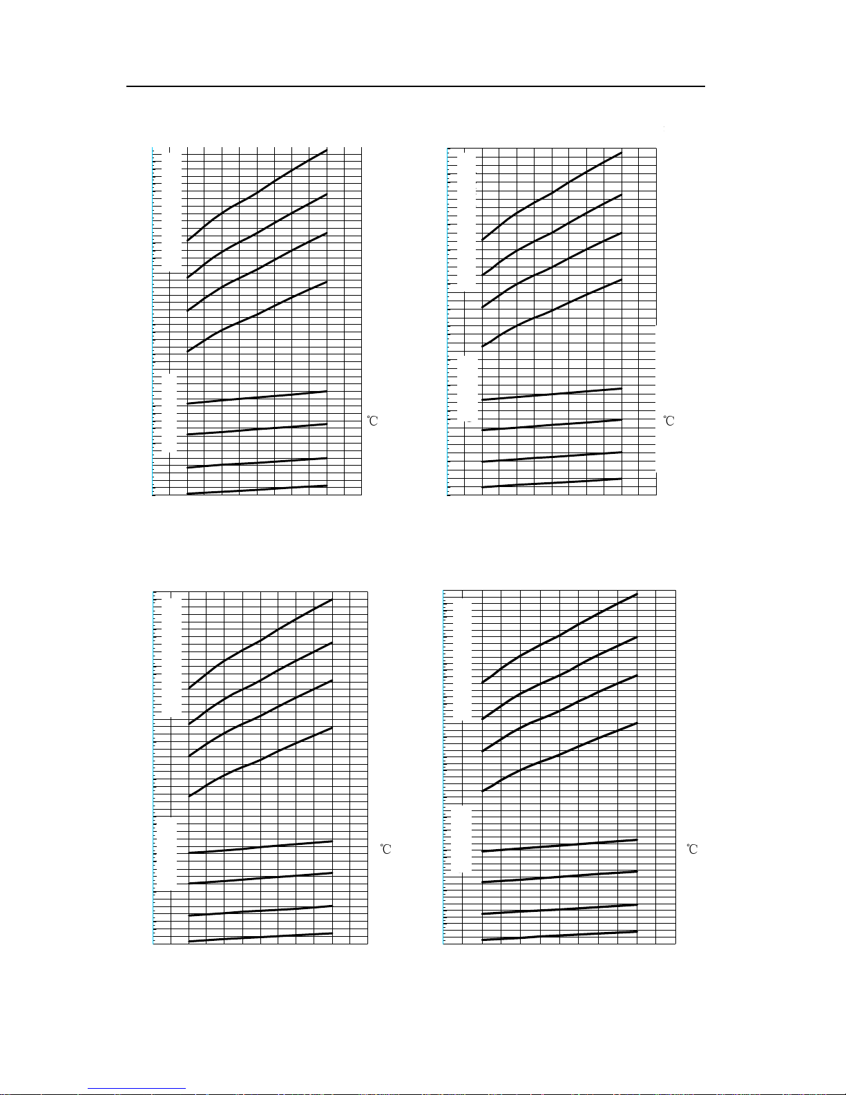
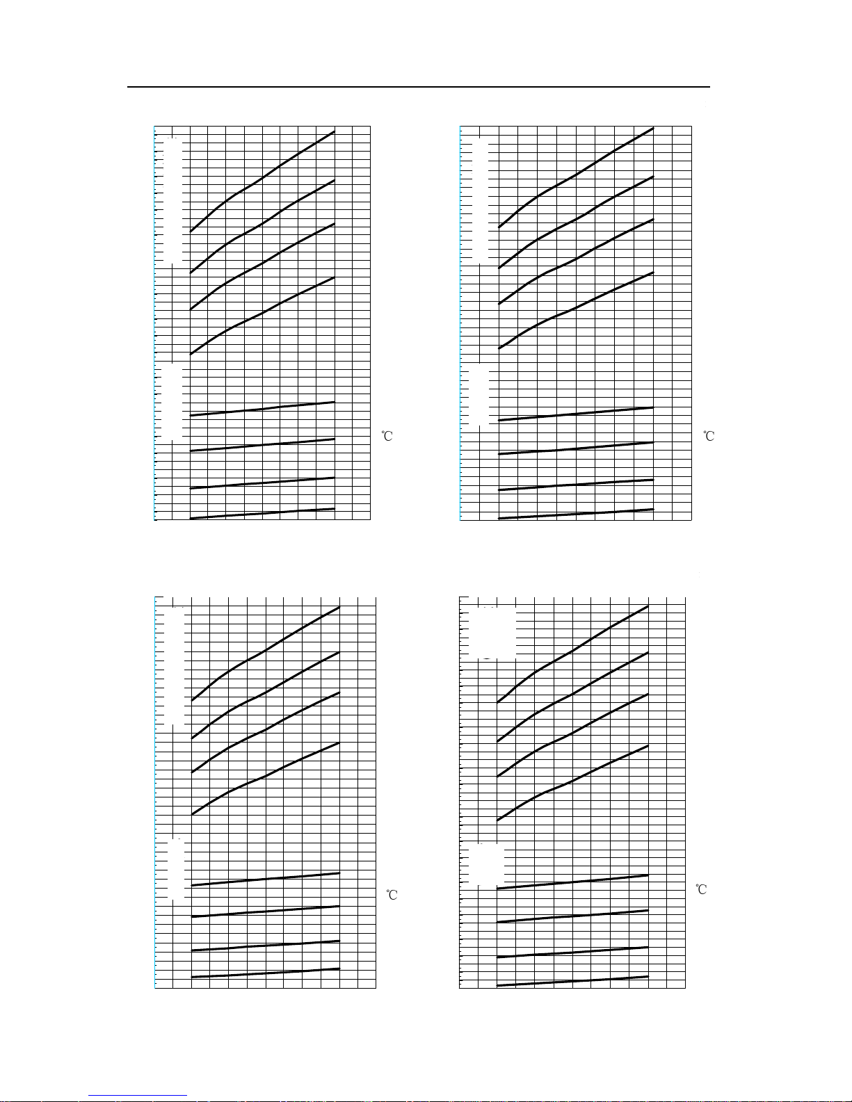
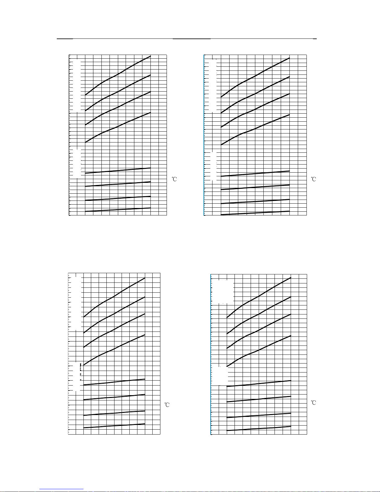
2.2.2 Variable Working Condition Table of Unit with Common Energy Efficiency
LSSLGS280MS变工况图表
20℃
25℃
25℃
30℃
30℃
35℃
35℃
363
357
351
345
339
333
327
321
315
309
303
297
291
285
279
273
267
261
255
249
243
237
231
225
67
65
63
61
59
57
55
53
51
49
47
43
45
20℃
4 5 6 7 8 9 10
冷冻水出水温度(℃)
LSSLGS315MS变工况图表
20℃
25℃
25℃
30℃
30℃
35℃
35℃
47
49
51
53
55
57
59
61
63
65
67
69
71
73
75
77
249
255
261
267
273
279
285
291
297
303
309
315
321
327
333
339
345
351
357
363
369
375
381
387
393
399
405
20℃
4 5 6 7 8 9 10
冷冻水出水温度(℃)
Specification of Cooling Capacity All Specifications
Power supply 380V3N~/50Hz
Voltage range 342~418V
Cooling
Inlet temperature range
of cooling water
19~38℃
Outlet temperature
range of chilled water
5~15℃
Chart of Variable Working Condition o
f
ACWCSC-960A5/MS
Chart of Variable Working Condition
of ACWCSC-1080A5/MS
Cooling Capacity (Kw)
Power (Kw)
Inlet temperature ofcooling water (
℃
)
Outlet temperature of chilled water (℃) Outlet temperature of chilled water (℃)
Inlet temperature ofcooling water (
℃
)
Powe
r
(Kw)
Cooling
Capacity
(Kw)
Page 13
Flooded Type Water Cooled Screw Chiller Technical M
anual
10
LSSLGS345MS变工况图表
20℃
25℃
25℃
30℃
30℃
35℃
35℃
441
435
429
423
417
411
405
399
393
387
381
375
369
363
357
351
345
339
333
327
321
315
309
303
297
291
285
279
273
83
81
79
77
75
73
71
69
67
65
63
61
59
57
55
53
20℃
4 5 6 7 8 9 10
冷冻水出水温度(℃)
LSSLGS405MS变工况图表
20℃
25℃
25℃
30℃
30℃
35℃
35℃
516
507
498
489
480
471
462
453
444
435
426
417
408
399
390
127
124
121
118
115
112
109
106
97
94
91
88
85
82
79
76
73
70
67
64
61
20℃
4 5 6 7 8 9 10
冷冻水出水温度(℃)
LSSLGS460MS变工况图表
20℃
25℃
25℃
30℃
30℃
35℃
35℃
591
582
573
564
555
546
537
528
519
510
501
492
483
474
465
456
447
438
429
420
411
402
393
384
375
106
103
100
97
94
91
88
85
82
79
76
73
70
67
20℃
4 5 6 7 8 9 10
冷冻水出水温度(℃)
LSSLGS510MS变工况图表
20℃
25℃
25℃
30℃
30℃
35℃
35℃
76
79
82
85
88
91
94
97
100
103
106
109
112
115
118
411
420
429
438
447
456
465
474
483
492
501
510
519
528
537
546
555
564
573
582
591
600
609
618
627
636
645
654
20℃
4 5 6 7 8 9 10
冷冻水出水温度(℃)
Chart of Variable Working Condition
of ACWCSC-1180A5/MS
Chart of Variable Working Condition
of ACWCSC-1380A5/MS
Cooling Capacity (Kw)
Power (Kw)
Power (Kw)
Cooling Capacity (Kw)
Inlet temperature ofcoolin
g
water
(℃)
Inlet temperature ofcooling water (
℃
)
Outlet temperature of chilled water (℃) Outlet temperature of chilled water (℃)
Outlet temperature of chilled water (℃) Outlet temperature of chilled water (℃)
Power (Kw)
Power (Kw)
Cooling Capacity (Kw)
Cooling Capacity (Kw)
Inlet temperature ofcooling water (
℃
)
Inlet temperature ofcooling water (
℃
)
Chart of Variable Working Condition
of ACWCSC-1570A5/MS
Chart of Variable Working Condition
of ACWCSC-1740A5/M
Page 14
Flooded Type Water Cooled Screw Chiller Technical M
anual
11
LSSLGS550MS变工况图表
20℃
25℃
25℃
30℃
30℃
35℃
35℃
82
85
88
91
94
97
100
103
106
109
112
115
118
121
124
127
447
456
465
474
483
492
501
510
519
528
537
546
555
564
573
582
591
600
609
618
627
636
645
654
663
672
681
690
699
20℃
4 5 6 7 8 9 10
冷冻水出水温度(℃)
LSSLGS620MS变工况图表
20℃
25℃
25℃
30℃
30℃
35℃
35℃
89
93
97
101
105
109
113
117
121
125
129
133
137
141
145
501
513
525
537
549
561
573
585
597
609
621
633
645
657
669
681
693
705
717
729
741
753
765
777
789
20℃
4 5 6 7 8 9 10
冷冻水出水温度(℃)
LSSLGS710MS变工况图表
20℃
25℃
25℃
30℃
30℃
35℃
35℃
105
109
113
117
121
125
129
133
137
141
145
149
153
157
161
165
573
585
597
609
621
633
645
657
669
681
693
705
717
729
741
753
765
777
789
801
813
825
837
849
861
873
885
897
909
20℃
4 5 6 7 8 9 10
冷冻水出水温度(℃)
LSSLGS800MS变工况图表
20℃
25℃
25℃
30℃
30℃
35℃
35℃
1017
1005
993
981
969
957
945
117
121
125
129
133
137
141
145
149
153
157
161
165
169
173
177
181
185
189
645
657
669
681
693
705
717
729
741
753
765
777
789
801
813
825
837
849
861
873
885
897
909
921
933
20℃
4 5 6 7 8 9 10
冷冻水出水温度(℃)
Chart of Variable Working Condition
of ACWCSC-1880A5/MS
Chart of Variable Working Condition
of ACWCSC-2120A5/MS
Outlet temperature of chilled water (℃) Outlet temperature of chilled water (℃)
Power (Kw)
Power (Kw)
Cooling Capacity (Kw)
Cooling Capacity (Kw)
Inlet temperature ofcoolin
g
water
(℃)
Inlet temperature ofcooling water (
℃
)
Chart of Variable Working Condition
of ACWCSC-2425A5/MS
Chart of Variable Working Condition
of ACWCSC-2730A5/MS
Inlet temperature o
f
cooling water (
℃
)
Inlet temperature o
f
cooling water (
℃
)
Outlet temperature of chilled water (℃) Outlet temperature of chilled water (℃)
Power (Kw)
Power (Kw)
Cooling Capacity (Kw)
Cooling Capacity (Kw)
Page 15
Flooded Type Water Cooled Screw Chiller Technical M
anual
12
LSSLGS900MS变工况图表
20℃
25℃
25℃
30℃
30℃
35℃
35℃
1146
137
142
147
152
157
162
167
172
177
182
187
192
197
202
207
212
726
741
756
771
786
801
816
831
846
861
876
891
906
921
936
951
966
981
996
1011
1026
1041
1056
1071
1086
1101
1116
1131
20℃
4 5 6 7 8 9 10
冷冻水出水温度(℃)
LSSLGS1020MD变工况图表
20℃
25℃
25℃
30℃
30℃
35℃
35℃
1293
1275
1257
1239
1221
1203
1185
1167
1149
1131
1113
1095
1077
1059
1041
1023
1005
987
969
951
933
915
897
879
861
843
825
807
235
229
223
217
211
205
199
193
187
181
175
169
163
157
151
20℃
4 5 6 7 8 9 10
冷冻水出水温度(℃)
LSSLGS1230MD变工况图表
20℃
25℃
25℃
30℃
30℃
35℃
35℃
1581
1557
1533
1509
1485
1461
1437
1413
1389
1365
1341
1317
1293
1269
1245
1221
1197
1173
1149
1125
1101
1077
1053
1029
1005
981
285
277
269
261
253
245
237
229
221
213
205
197
189
181
173
20℃
4 5 6 7 8 9 10
冷冻水出水温度(℃)
LSSLGS1420MD变工况图表
20℃
25℃
25℃
30℃
30℃
35℃
35℃
1725
1701
1677
1653
1629
1605
1581
1557
1533
1509
1485
1461
1437
1413
1389
1365
1341
1317
1293
1269
1245
1221
1197
1173
1149
1125
333
325
317
309
301
293
285
277
269
261
253
245
237
229
221
213
1749
1773
1797
1821
20℃
4 5 6 7 8 9 10
冷冻水出水温度(℃)
Chart of Variable Working Condition
of ACWCSC-3070A5/MS
Chart of Variable Working Condition of
ACWCSC-3480A5/MD
Inlet temperature ofcooling water (
℃
)
Inlet temperature ofcooling water (
℃
)
Outlet temperature of chilled water (℃) Outlet temperature of chilled water (℃)
Power (Kw)
Cooling Capacity (Kw)
Cooling Capacity (Kw)
Power (Kw)
Cooling Capacity (Kw)
Cooling
Capacity
(Kw)
Powe
r
(Kw)
Power (Kw)
Outlet temperature of chilled water (℃) Outlet temperature of chilled water (℃)
Inlet temperature ofcooling water (
℃
)
Inlet temperature ofcooling water (
℃
)
Chart of Variable Working Condition
of ACWCSC-4200A5/MD
Chart of Variable Working Condition
of ACWCSC-4845A5/MD
Page 16
Flooded Type Water Cooled Screw Chiller Technical M
anual
13
LSSLGS1600MD变工况图表
20℃
25℃
25℃
30℃
30℃
35℃
35℃
2031
2001
1971
1941
1911
1881
1851
1821
1791
1761
1731
1701
1671
1641
1611
1581
1551
1521
1491
1461
1431
1401
1371
1341
1311
1281
377
367
357
347
337
327
317
307
297
287
277
267
257
247
237
227
20℃
4 5 6 7 8 9 10
冷冻水出水温度(℃)
LSSLGS1800MD变工况图表
20℃
25℃
25℃
30℃
30℃
35℃
35℃
2301
2265
2229
2193
2157
2121
2085
2049
2013
1977
1941
1905
1869
1833
1797
1761
1725
1689
1653
1617
1581
1545
1509
1473
1437
421
409
397
385
373
361
349
337
325
313
301
289
277
265
20℃
4 5 6 7 8 9 10
冷冻水出水温度(℃)
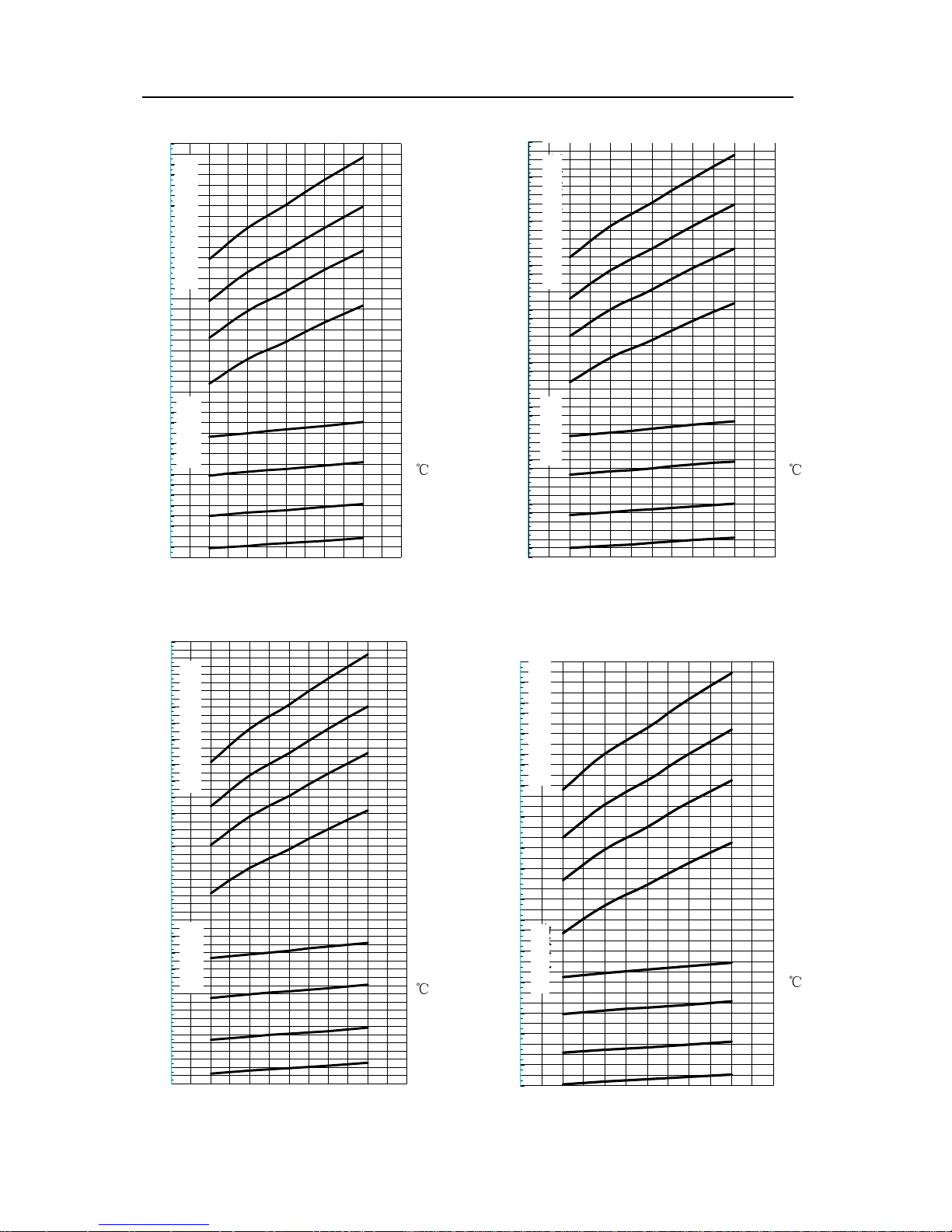
2.2.3 Variable Working Condition Table of Unit with High Energy Efficiency
LSSLGS280MSG变工况图表
20℃
25℃
25℃
30℃
30℃
35℃
35℃
354
354
347
340
333
326
319
312
305
298
291
284
277
270
263
256
249
242
235
228
61
59
57
55
53
51
49
47
43
41
39
45
37
20℃
4 5 6 7 8 9 10
冷冻水出水温度(℃)
LSSLGS315MSG变工况图表
20℃
25℃
25℃
30℃
30℃
35℃
35℃
403
396
389
382
375
368
361
354
347
340
333
326
319
312
305
298
291
284
277
270
263
256
69
67
65
63
61
59
57
55
53
51
49
47
43
45
20℃
4 5 6 7 8 9 10
冷冻水出水温度(℃)
Chart of Variable Working Condition
of ACWCSC-5460A5/MD
Chart of Variable Working Condition
of ACWCSC-6140A5/MD
Outlet temperature of chilled water (℃) Outlet temperature of chilled water (℃)
Power (Kw)
Power (Kw)
Cooling Capacity (Kw)
Cooling Capacity (Kw)
Inlet temperature ofcooling water (
℃
)
Inlet temperature ofcooling water (
℃
)
Chart of Variable Working Condition
of ACWCSC-960A5/MSG
Outlet temperature of chilled water (℃) Outlet temperature of chilled water (℃)
Inlet temperature ofcooling water (
℃
)
Inlet temperature ofcooling water (
℃
)
Chart of Variable Working Condition
of ACWCSC-1080A5/MSG
Cooling Capacity (Kw)
Power (Kw)
Powe
r
(Kw)
Cooling
Capacity
(Kw)
Page 17
Flooded Type Water Cooled Screw Chiller Technical M
anual
14
LSSLGS345MSG变工况图表
20℃
25℃
25℃
30℃
30℃
35℃
35℃
445
438
431
424
417
410
403
396
389
382
375
368
361
354
347
340
333
326
319
312
305
298
291
284
277
75
73
71
69
67
65
63
61
59
57
55
53
51
49
47
20℃
4 5 6 7 8 9 10
冷冻水出水温度(℃)
LSSLGS405MSG变工况图表
20℃
25℃
25℃
30℃
30℃
35℃
35℃
522
515
508
501
494
487
480
473
466
459
452
445
438
431
424
417
410
403
396
389
382
375
368
361
354
347
340
333
326
87
85
83
81
79
77
75
73
71
69
67
65
63
61
59
57
55
20℃
4 5 6 7 8 9 10
冷冻水出水温度(℃)
LSSLGS460MSG变工况图表
20℃
25℃
25℃
30℃
30℃
35℃
35℃
592
585
578
571
564
557
550
543
536
529
522
515
508
501
494
487
480
473
466
459
452
445
438
431
424
417
410
403
396
389
382
375
368
97
95
93
91
89
87
85
83
81
79
77
75
73
71
69
67
65
63
61
20℃
4 5 6 7 8 9 10
冷冻水出水温度(℃)
LSSLGS510MSG变工况图表
20℃
25℃
25℃
30℃
30℃
35℃
35℃
70
73
76
79
82
85
88
91
94
97
100
103
106
411
420
429
438
447
456
465
474
483
492
501
510
519
528
537
546
555
564
573
582
591
600
609
618
627
636
645
654
20℃
4 5 6 7 8 9 10
冷冻水出水温度(℃)
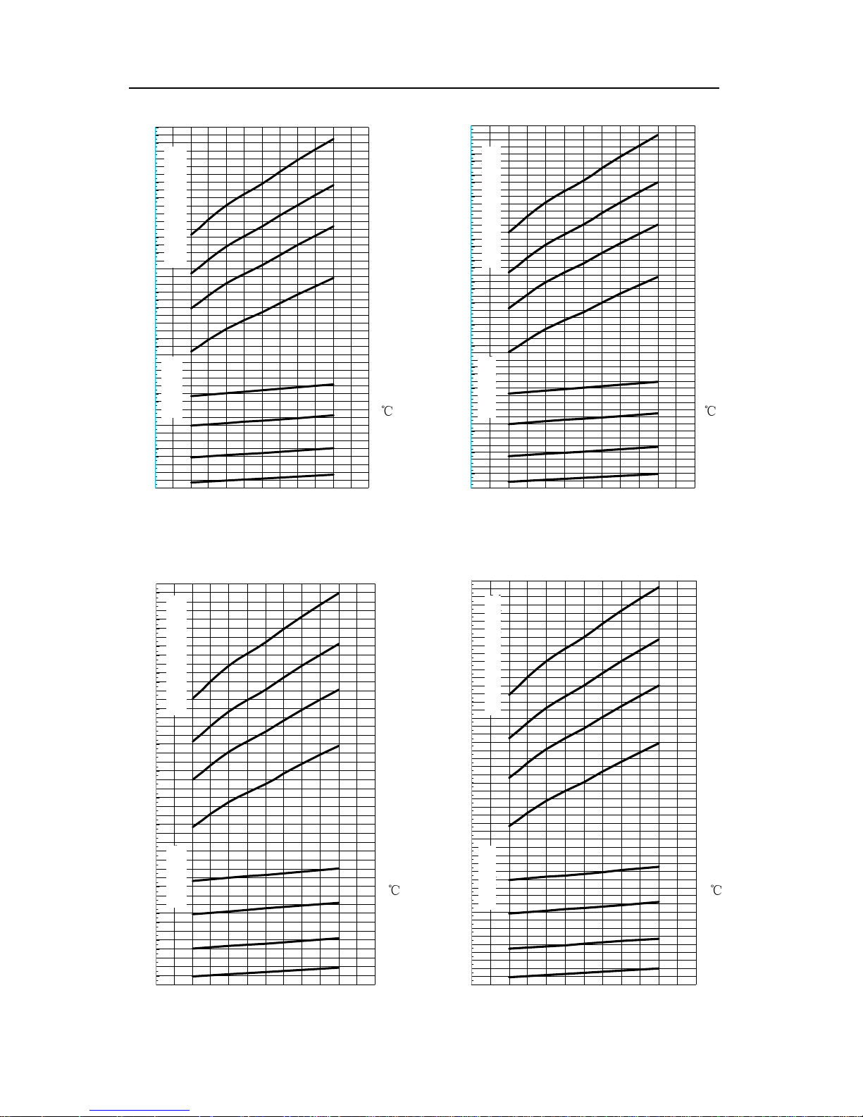
Chart of Variable Working Condition
of ACWCSC-1180A5/MSG
Cooling Capacity (Kw)
Power (Kw)
Outlet temperature of chilled water (℃)
Inlet temperature ofcooling water (
℃
)
Chart of Variable Working Condition
of ACWCSC-1380A5/MSG
Cooling Capacity (Kw)
Power (Kw)
Inlet temperature ofcooling water (
℃
)
Outlet temperature of chilled water (℃)
Chart of Variable Working Condition
of ACWCSC-1570A5/MSG
Cooling Capacity (Kw)
Power (Kw)
Inlet temperature ofcooling water (
℃
)
Outlet temperature of chilled water (℃) Outlet temperature of chilled water (℃)
Cooling Capacity (Kw)
Power (Kw)
Inlet temperature ofcooling water (
℃
)
Chart of Variable Working Condition
of ACWCSC-1740A5/MSG
Page 18
Flooded Type Water Cooled Screw Chiller Technical M
anual
15
LSSLGS550MSG变工况图表
20℃
25℃
25℃
30℃
30℃
35℃
35℃
73
76
79
82
85
88
91
94
97
100
103
106
109
112
115
447
456
465
474
483
492
501
510
519
528
537
546
555
564
573
582
591
600
609
618
627
636
645
654
663
672
681
690
699
708
20℃
4 5 6 7 8 9 10
冷冻水出水温度(℃)
LSSLGS620MSG变工况图表
20℃
25℃
25℃
30℃
30℃
35℃
35℃
82
85
88
91
94
97
100
103
106
109
112
115
118
121
124
127
130
498
507
516
525
534
543
552
561
570
579
588
597
606
615
624
633
642
651
660
669
678
687
696
705
714
723
732
741
750
759
768
777
786
795
20℃
4 5 6 7 8 9 10
冷冻水出水温度(℃)
LSSLGS710MSG变工况图表
20℃
25℃
25℃
30℃
30℃
35℃
35℃
93
97
101
105
109
113
117
121
125
129
133
137
141
145
149
573
585
597
609
621
633
645
657
669
681
693
705
717
729
741
753
765
777
789
801
813
825
837
849
861
873
885
897
909
20℃
4 5 6 7 8 9 10
冷冻水出水温度(℃)
LSSLGS800MSG变工况图表
20℃
25℃
25℃
30℃
30℃
35℃
35℃
1020
105
109
113
117
121
125
129
133
137
141
145
149
153
157
161
165
169
648
660
672
684
696
708
720
732
744
756
768
780
792
804
816
828
840
852
864
876
888
900
912
924
936
948
960
972
984
996
1008
20℃
4 5 6 7 8 9 10
冷冻水出水温度(℃)
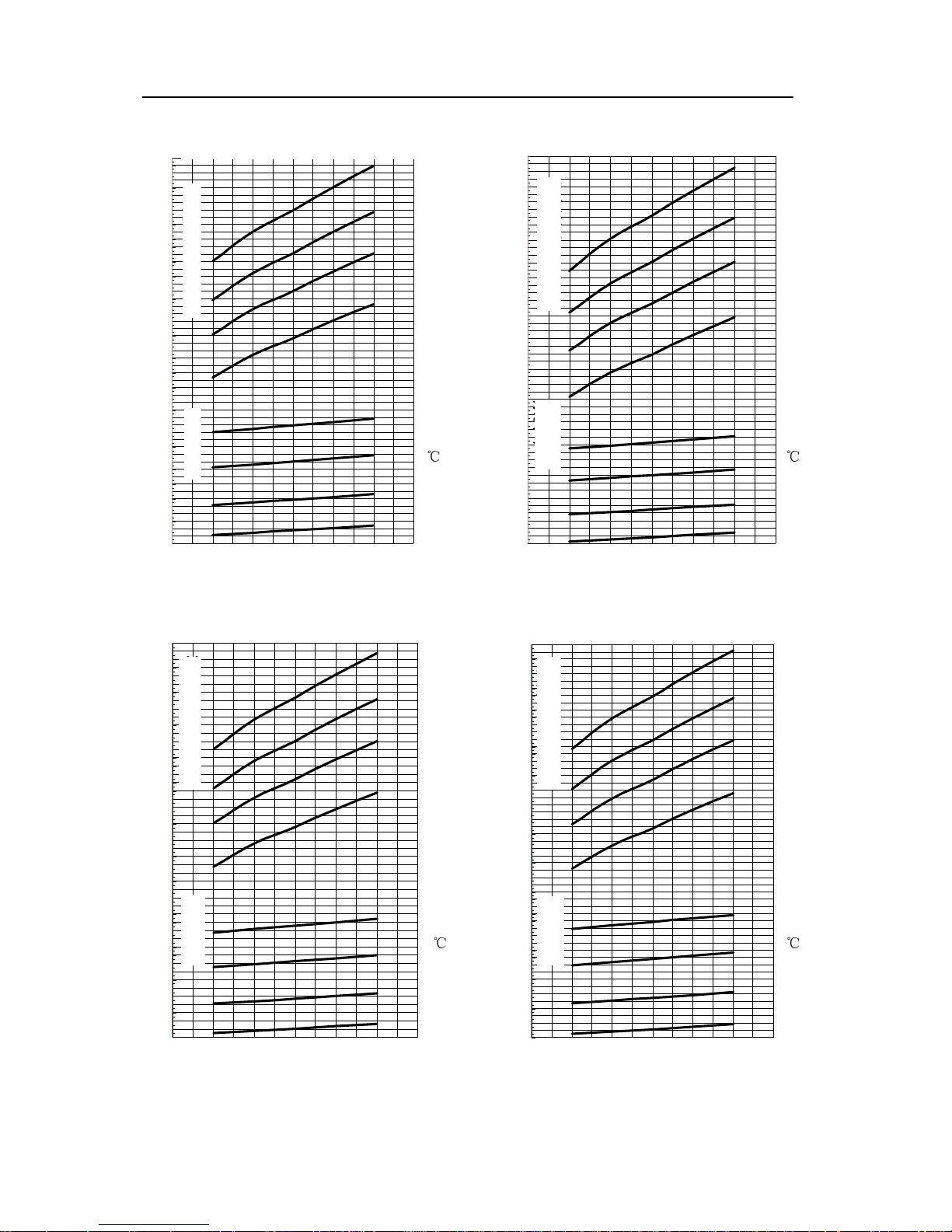
Chart of Variable Working Condition
of ACWCSC-1880A5/MSG
Chart of Variable Working Condition
of ACWCSC-2425A5/MSG
Chart of Variable Working Condition
of ACWCSC-2730A5/MSG
Chart of Variable Working Condition
of ACWCSC-2120A5/MSG
Cooling Capacity (Kw)
Cooling Capacity (Kw)
Cooling Capacity (Kw)
Cooling Capacity (Kw)
Inlet temperature ofcooling water (
℃
)
Inlet temperature ofcooling water (
℃
)
Inlet temperature ofcooling water (
℃
)
Inlet temperature ofcooling water (
℃
)
Power (Kw)
Power (Kw)
Power (Kw)
Power (Kw)
Outlet temperature of chilled water (℃) Outlet temperature of chilled water (℃)
Outlet temperature of chilled water (℃) Outlet temperature of chilled water (℃)
Page 19
Flooded Type Water Cooled Screw Chiller Technical M
anual
16
LSSLGS900MSG变工况图表
20℃
25℃
25℃
30℃
30℃
35℃
35℃
1152
1138
1124
1110
1096
1082
1068
121
125
129
133
137
141
145
149
153
157
161
165
169
173
177
181
185
189
193
718
732
746
760
774
788
802
816
830
844
858
872
886
900
914
928
942
956
970
984
998
1012
1026
1040
1054
20℃
4 5 6 7 8 9 10
冷冻水出水温度(℃)
LSSLGS1020MDG变工况图表
20℃
25℃
25℃
30℃
30℃
35℃
35℃
1311
1296
1281
1266
1251
137
142
147
152
157
162
167
172
177
182
187
192
197
202
207
212
816
831
846
861
876
891
906
921
936
951
966
981
996
1011
1026
1041
1056
1071
1086
1101
1116
1131
1146
1161
1176
1191
1206
1221
1236
20℃
4 5 6 7 8 9 10
冷冻水出水温度(℃)
LSSLGS1230MDG变工况图表
20℃
25℃
25℃
30℃
30℃
35℃
35℃
1579
1558
1537
163
169
175
181
187
193
199
205
211
217
223
229
235
241
247
253
259
970
991
1012
1033
1054
1075
1096
1117
1138
1159
1180
1201
1222
1243
1264
1285
1306
1327
1348
1369
1390
1411
1432
1453
1474
1495
1516
20℃
4 5 6 7 8 9 10
冷冻水出水温度(℃)
LSSLGS1420MDG变工况图表
20℃
25℃
25℃
30℃
30℃
35℃
35℃
1810
1789
1768
1747
1726
1705
1684
1663
1642
1621
1600
1579
1558
1537
193
199
205
211
217
223
229
235
241
247
253
259
265
271
277
283
289
295
301
1138
1159
1180
1201
1222
1243
1264
1285
1306
1327
1348
1369
1390
1411
1432
1453
1474
1495
1516
20℃
4 5 6 7 8 9 10
冷冻水出水温度(℃)
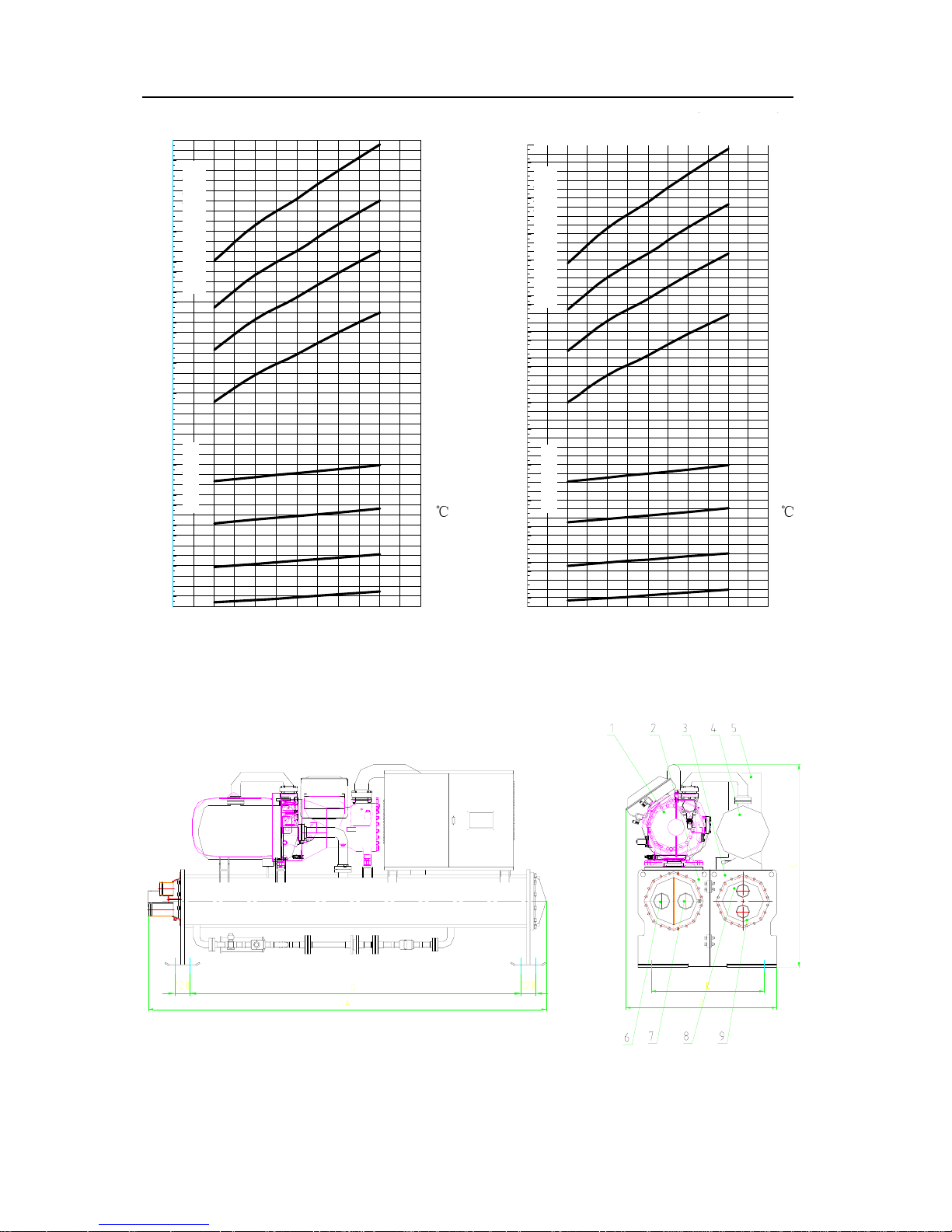
Chart of Variable Working Condition
of ACWCSC-3070A5/MSG
Inlet temperature ofcooling water (
℃
)
Power (Kw)
Cooling Capacity (Kw)
Outlet temperature of chilled water (℃)
Chart of Variable Working Condition
ofACWCSC-3480A5/MDG
Chart of Variable Working Condition
of ACWCSC-4200A5/MDG
Chart of Variable Working Condition
of ACWCSC-4845A5/MDG
Power (Kw)
Power (Kw)
Power (Kw)
Outlet temperature of chilled water (℃) Outlet temperature of chilled water (℃)
Outlet temperature of chilled water (℃)
Cooling Capacity (Kw)
Cooling Capacity (Kw)
Cooling Capacity (Kw)
Inlet temperature ofcooling water (
℃
)
Inlet temperature ofcooling water (
℃
)
Inlet temperature ofcooling water (
℃
)
Page 20
Flooded Type Water Cooled Screw Chiller Technical M
anual
17
LSSLGS1600MDG变工况图表
20℃
25℃
25℃
30℃
30℃
35℃
35℃
2034
2006
213
221
229
237
245
253
261
269
277
285
293
301
309
317
325
333
1278
1306
1334
1362
1390
1418
1446
1474
1502
1530
1558
1586
1614
1642
1670
1698
1726
1754
1782
1810
1838
1866
1894
1922
1950
1978
20℃
4 5 6 7 8 9 10
冷冻水出水温度(℃)
LSSLGS1800MDG变工况图表
20℃
25℃
25℃
30℃
30℃
35℃
35℃
2286
2258
2230
2202
2174
2146
2118
2090
2062
2034
2006
237
245
253
261
269
277
285
293
301
309
317
325
333
341
349
357
365
373
1418
1446
1474
1502
1530
1558
1586
1614
1642
1670
1698
1726
1754
1782
1810
1838
1866
1894
1922
1950
1978
20℃
4 5 6 7 8 9 10
冷冻水出水温度(℃)
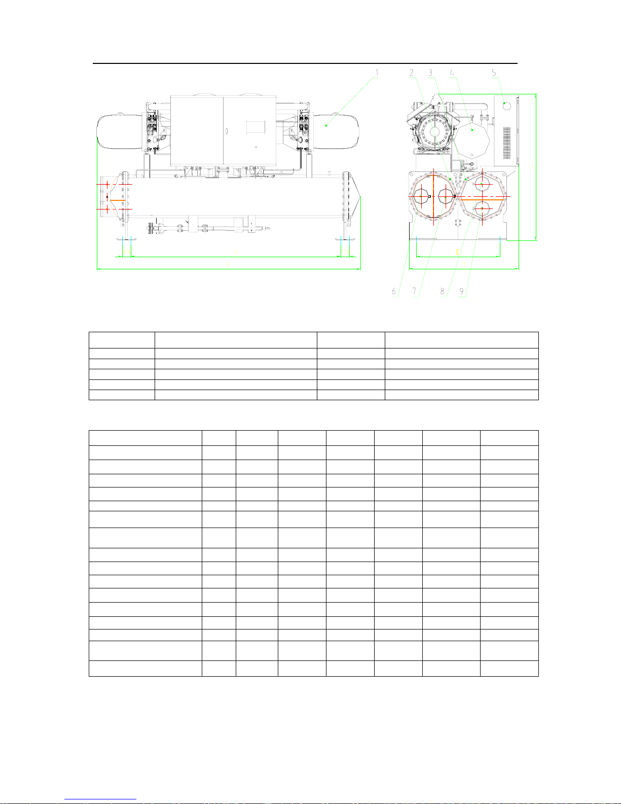
3. Outline Dimension of Unit
Outline and connection dimension diagram of unit – single compressor (ACWCSC-960A5/MS~ ACWCSC-3070A5/MS )
Outlet temperature of chilled water (℃) Outlet temperature of chilled water (℃)
Chart of Variable Working Condition
o
f
ACWCSC-5460A5/MDG
Chart of Variable Working Condition
of ACWCSC-6140A5/MDG
Inlet temperature ofcooling water (
℃
)
Inlet temperature ofcooling water (
℃
)
Power (Kw)
Power (Kw)
Cooling Capacity (Kw)
Cooling Capacity (Kw)
Page 21
Flooded Type Water Cooled Screw Chiller Technical M
anual
18
Outline and connection dimension diagram of unit – twin-compressor (ACWCSC-3480A5/MD~ ACWCSC-6140A5/MD)
Sign Name Sign Name
① screw compressor ⑥ Inlet of chilled water
② evaporator ⑦ outlet of chilled water
③ condenser ⑧ Outlet of cooling water
④ oil separator ⑨ inlet of cooling water
⑤ Control cabinet
Dimension of twin-screw water-cooled chiller unit: Unit: mm
Model A B C D E DNX DNY
ACWCSC-960A5/MS(G) 3200 1150 1500 2600 900 DN100 DN100
ACWCSC-1080A5/MS(G) 3200 1150 1500 2600 900 DN100 DN100
ACWCSC-1180A5/MS(G) 3250 1150 1500 2730 960 DN125 DN125
ACWCSC-1380A5/MS(G) 3250 1200 1630 2730 1000 DN125 DN125
ACWCSC-1570A5/MS (G) 3250 1200 1670 2730 1000 DN125 DN125
ACWCSC-1740A5/MG 3250 1200 1670 2730 1000 DN125 DN125
ACWCSC-1740A5/M
ACWCSC-1880A5/MS(G)
3500 1300 1700 2800 1100 DN150 DN150
ACWCSC-2120A5/MS(G) 3550 1350 1700 2800 1100 DN150 DN150
ACWCSC-2425A5/MS(G) 3550 1350 1850 2800 1100 DN150 DN150
ACWCSC-2730A5/MS(G) 3550 1400 1850 2800 1200 DN150 DN150
ACWCSC-3070A5/MS (G) 3550 1400 1960 2800 1200 DN150 DN200
ACWCSC-3480A5/MD(G) 4120 1400 2050 3300 1200 DN200 DN200
ACWCSC-4200A5/MD(G) 4180 1400 2050 3300 1200 DN200 DN200
ACWCSC-4845A5/MDG 4180 1550 2100 3300 1250 DN250 DN250
ACWCSC-4845A5/MD
ACWCSC-5460A5/MD(G)
4680 1550 2100 3800 1300 DN250 DN250
ACWCSC-6140A5/MD(G) 4680 1700 2100 3800 1500 DN250 DN250
Page 22
Flooded Type Water Cooled Screw Chiller Technical M
anual
19
Chapter II Installation and Commissioning
1 Preparation and Tools before Installation
1.1 Preparation before Installation
1.Dedicated machine room should be available for unit. Measures should be taken to exhaust
heat generated by unit during operation and ventilation volume should be able to keep
maintain room temperature no more than 40 . ℃
2. Unit should be installed on non-deformable rigid pedestal or concrete foundation that should
be flat and stand weight of unit during operation.
3. Sufficient drainage measures such as draining channel should be available for around the
foundation of unit to discharge water from system in case of seasonal shutdown or
maintenance.
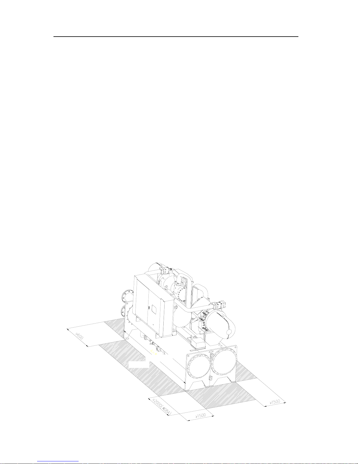
4.Machine room should be spacious enough to install and maintain unit, and pull pipe;
meanwhile, pipeline and line pipe shouldn’t be laid above compressor; the distance from the
highest point of unit to the top of machine room shouldn’t be less than 500mm. See the
following diagram for space requirement.
A
= length of uni
t
Maintenance space
Front of unit
Page 23

Flooded Type Water Cooled Screw Chiller Technical M
anual
20
5.When installing water pipe, it’s recommended to reserve space between water pipe and
connecting pipe to install damping rubber connecting pipe, and to provide suitable
construction and adjustment space after unit arrives at site.
6.To ensure normal working of electrical elements, don’t put unit at places with dust, filth and
much corrosive fume that must be corrected if any.
1.2 Tools to be Prepared
Flexible joint, anti-vibration bolster, lifting equipment, lifting beam, lifting chain, lifting jack, skid,
underlay roll and crow bar
2 Installation of Unit
1. Before leaving factory, unit has been subjected to strict inspection and package to ensure
unit arrives at destination under normal conditions. Installers, handlers and lifting worker
should protect unit, prevent damaging unit due to rough operation and especially pay
attention to preventing refrigerant leaking due to impact on angle valve and pipeline.
2. Unit should be moved horizontally with gradient no more than 30°. It’s allowed to use crane.
When using crane, it’s required to use bottom lug hole. Contact part between sling and unit
should be separated with support. It’s necessary to ensure sling can stand weight of the
whole unit, otherwise, unit will be damaged or serious physical injury will be caused. Don’t lift
or move unit with forklift.
3. If vertical lifting conditions are or available, horizontal rolling method can be used. In other
words, prop up both ends with lifting jack to a certain height, put underlay roll under skid
support of unit, and remove skid after rolling unit into proper position. When moving unit with
horizontal rolling method, it’s only allowed to apply force on unit frame or skid.
4. After unit is put into proper position, remove skid, adjust levelness with spirit level and fix
footing of unit on foundation with anchor bolt. It’s recommended to put anti-vibration flexible
pad with thickness of 15~20mm between footing of unit and foundation.
5. When unit is put into proper position, put anti-vibration flexible pad under unit, and adjust
levelness of unit within a range of 2mm per meter. Unit should be leveled with gasket of
Page 24
Flooded Type Water Cooled Screw Chiller Technical M
anual
21
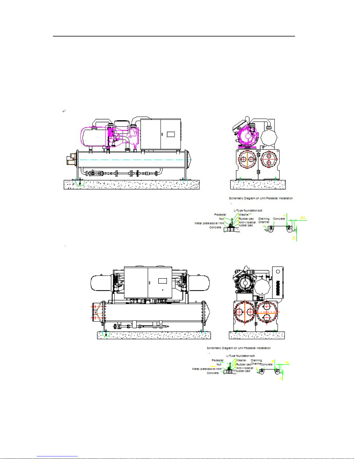
standard length. Unit must be put inside machine room and non-deformable rigid pedestal
or concrete foundation should be provided. It’s recommended to install unit at basement or
ground floor. If it’s required to install at high floor, it’s necessary to consider if basic
structure of floor has sufficient strength to stand weight of chiller unit during operation. Unit
should be installed as follows:
Installation Diagram of Unit – Single Compressor (ACWCSC-960A5/MS~ ACWCSC-3070A5/MS )
Installation Diagram of Unit – Twin-Compressor (ACWCSC-3480A5/MD~ ACWCSC-6140A5/MD)
Page 25

Flooded Type Water Cooled Screw Chiller Technical M
anual
22
3 Connection of Water Pipeline
After installing unit into proper position, conduct installation of water system pipeline or connect the
arranged water system pipeline with water pipe of evaporator and condenser.
3.1 Basic Requirements of Pipeline Connection
1.Installation and insulation of water pipeline of A/C system should be designed and instructed
by professional designers, and should follow relevant requirements of heating A/C system
installation specification.
2.Inlet & outlet water pipeline should be connected according to requirements indicated on unit.
3.Water system must be equipped with water pump of suitable flow and lift to ensure unit can
set water supply. Water pump should be connected to unit and water system pipeline with anti-
vibration flexible joint, and should also be self-supported to prevent applying force on unit. During
installation, welding should prevent damaging unit. (Add requirements for flange connection)
4.Install flow switch (to be supplied by AUKS, excluding joint) on outlet water pipe of evaporator
and condenser. Interlock input contact in flow switch and control cabinet. The installation
requirements are as follows:
Flow switch is single-pole double-throw (SPDT) flow switch used to induct flow change
of liquid such as water, glycol or other non-hazardous fluids flowing across pipeline. It is
typically used at places requiring linkage function or “discontinuous flow” protection.
When installing flow switch, its wiring terminal should be installed at the position that is
easy for wiring.
Tightly screw slow switch to keep liquid flow at a correct angle, arrow on enclosure must
be in the same direction as that of liquid flow.
Page 26
Flooded Type Water Cooled Screw Chiller Technical M
anual
23
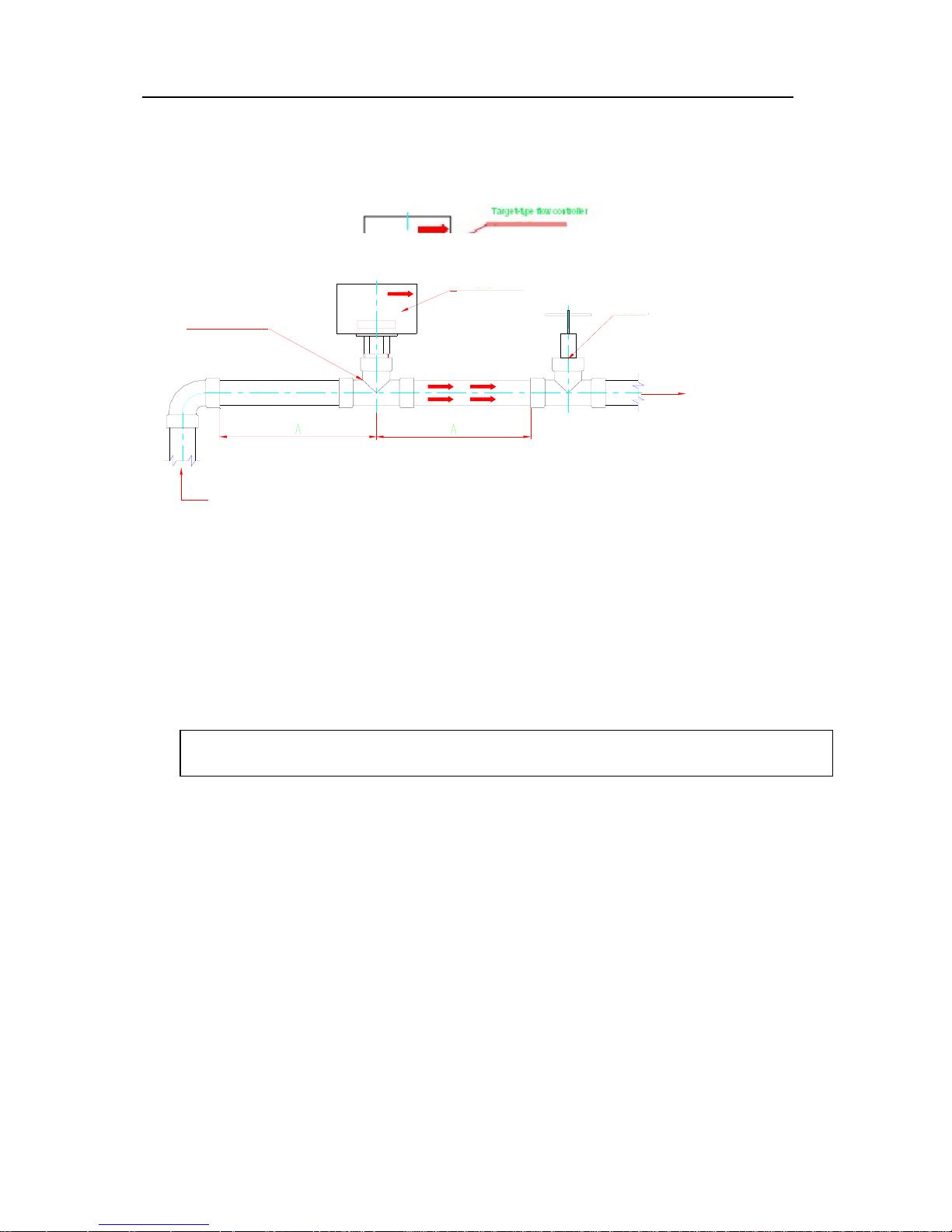
Flow switch must be installed on a section of straight pipeline and there should be at
least straight line travel five times of pipe diameter at both sides. (see the diagram
below)
5. Water filter of 16~40 meshes must be installed in front of inlet pipeline of unit.
6.Water pipeline of system should be flushed before connecting unit to prevent filth damaging unit.
7.Water chamber is designed to stand water pressure of 1.0Mpa. Don’t use it under excessive
pressure to prevent damaging evaporator and condenser.
3.2 Pipeline Connection of Condenser
1.Pipeline system of cooling water must be connected with outlet water pipeline of cooling tower
after it is connected with anti-vibration flexible joint, thermometer, pressure gauge, drain
valve, stop valve, water filter, check valve and target-type flow controller.
2.Water supply pipeline should be as short as possible. Specification of pipeline should be
determined by effective lift of water pump, flow and flow rate of pipeline, rather than
specification of joint.
3.Drainage and discharge joints are installed at sealing end of condenser and sealed with screw
plug. Screw plug should be replaced with (1/4NPT discharge and 1/2NPT drainage) ball
Note: It’s strictly prohibited to connect pipeline with unit before thoroughly
flushing the pipeline.
Three-way joint or
welded two-way joint
Water flow swtich
Stop valve
Flow direction
Size “A” must be at least five times of pipe diameter from the nearest
elbow, valve or other pipe res
trictor
s
Flow direction
Page 27
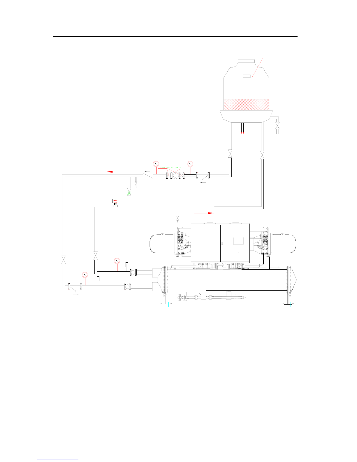
Flooded Type Water Cooled Screw Chiller Technical M
anual
24
valve.
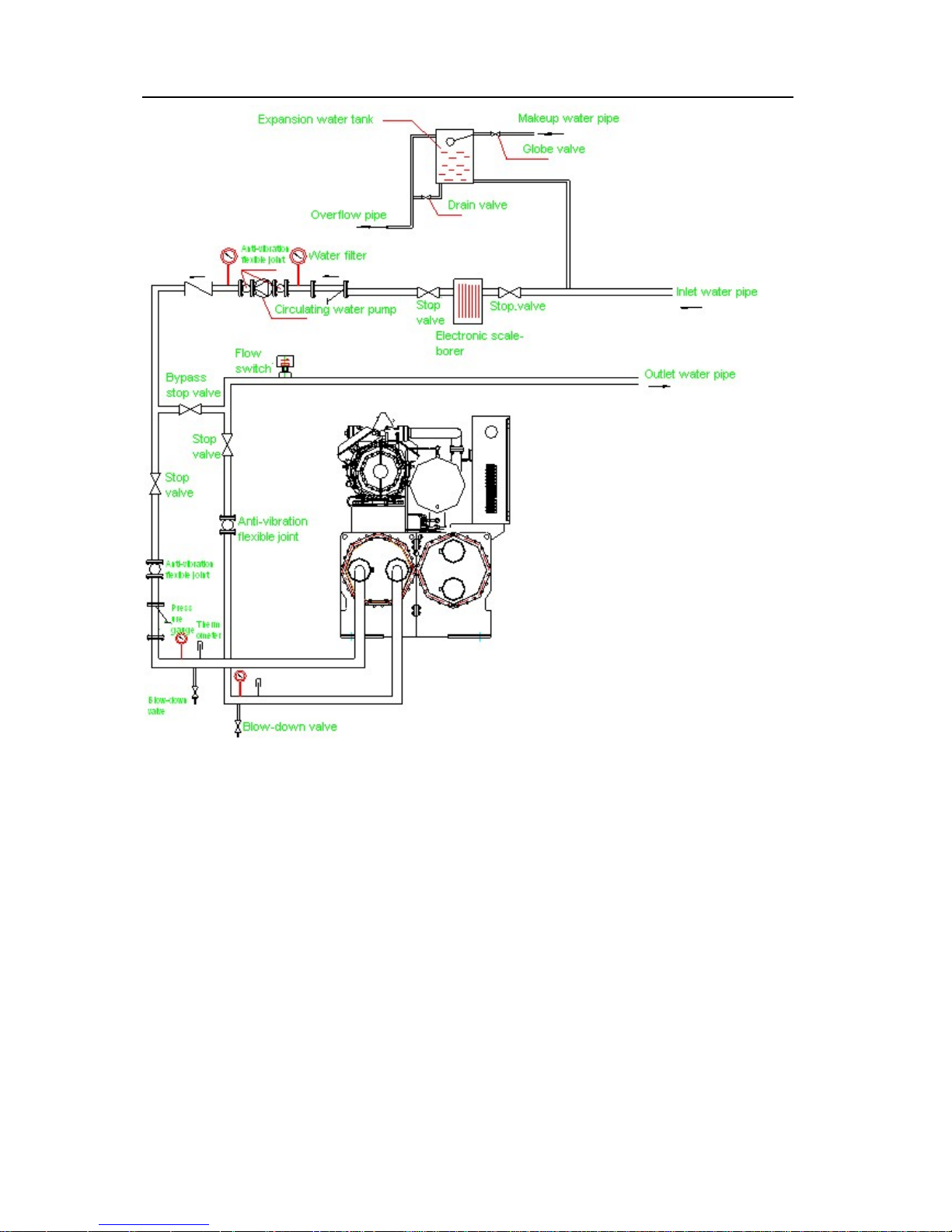
3.3 Pipeline Connection of Evaporator
1.Pipeline system of refrigeration water must be installed with anti-vibration joint, thermometer,
pressure gauge, water filter, electronic scale-borer, check valve, target-type flow controller,
discharge valve, drainage valve, stop valve and expansion water tank, etc.
2.Expansion water tank should be installed at the location 1~1.5m away from the highest point
of system. Capacity of water tank should be approximately 1/10 of water volume of the whole
Target-type flow controller
A
utomatic makeup valve
Stop valve
Overflow pipe
Stop valve
Water filter
Circulating water
pump with
A
nti-vibration
flexible joint
Inlet pipe of cooling water
Blow-down valve
Bypass stop valve
Flow switch
Blow-down valve
Outlet pipe of cooling water
Stop valve
Pressur
e gauge
Thermomet
Page 28
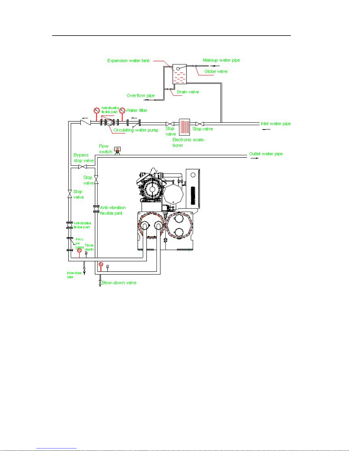
Flooded Type Water Cooled Screw Chiller Technical M
anual
25
system.
3.Discharge valve is installed on cylinder of evaporator.
4.Vertical change should be prevented for water pipe where possible. Manual or automatic
discharge valve should be installed between high part of pipeline and expansion water tank.
5.Thermometer and pressure gauge should be installed at straight pipe section of inlet and
outlet water pipeline, which shouldn’t be installed at the location near elbow pipe where
possible. Bypass pipeline should be installed between inlet and outlet water pipes of
evaporator to facilitate cleaning and overhauling pipeline.
6.Drain valve (wash-out valve) should be installed at the lowest part of inlet and outlet water
pipeline of unit. Drainage pipe should be connected to the lowest side of system to discharge
refrigeration water of unit from two outlets, prevent refrigeration water freezing in heat
exchanger and water pump in winter, and prevent damaging unit when it is not used in winter.
7.Separate support should be installed for pipeline of water system and external force
shouldn’t be applied on main unit. Usually, spacing of support is determined by material
performance and pipe diameter.
8.Pipeline of refrigeration water and expansion water tank should be insulated. Maintenance
space should be reserved at joint of valves.
9.Pipeline should be wrapped with insulation layer after airtight test to prevent heat transfer
and sweating. Insulation layer should be covered with damp-proof sealing device.
Page 29
Flooded Type Water Cooled Screw Chiller Technical M
anual
26
4 Electrical Wiring
Electrical wiring must comply with low-voltage distribution device and circuit design specification.
Low-voltage circuit breaker for short circuit protection should be installed for power supply circuit.
Rated current of circuit breaker should be at least one class higher than max operating current of
unit.Setting current of transient overcurrent release shouldn’t be more than 1/1.3 of short circuit
current if unit.
4.1 Requirements for Power Supply
1.Power supply of unit should use dedicated power supply system. Total power supply capacity
must be more than the power corresponding to max operating current of unit.
2. Power supply system of unit: three-phase five-wire system: 380V 3N~/50Hz.
Page 30
Flooded Type Water Cooled Screw Chiller Technical M
anual
27
3.Permissible tolerance of source voltage is ±10% and unbalance of phase voltage is less than
2.25%.
%100
voltageaverage
voltageaverage-eMax.voltag
ratiounbalancevoltage ×=
4.2 Wiring Requirements
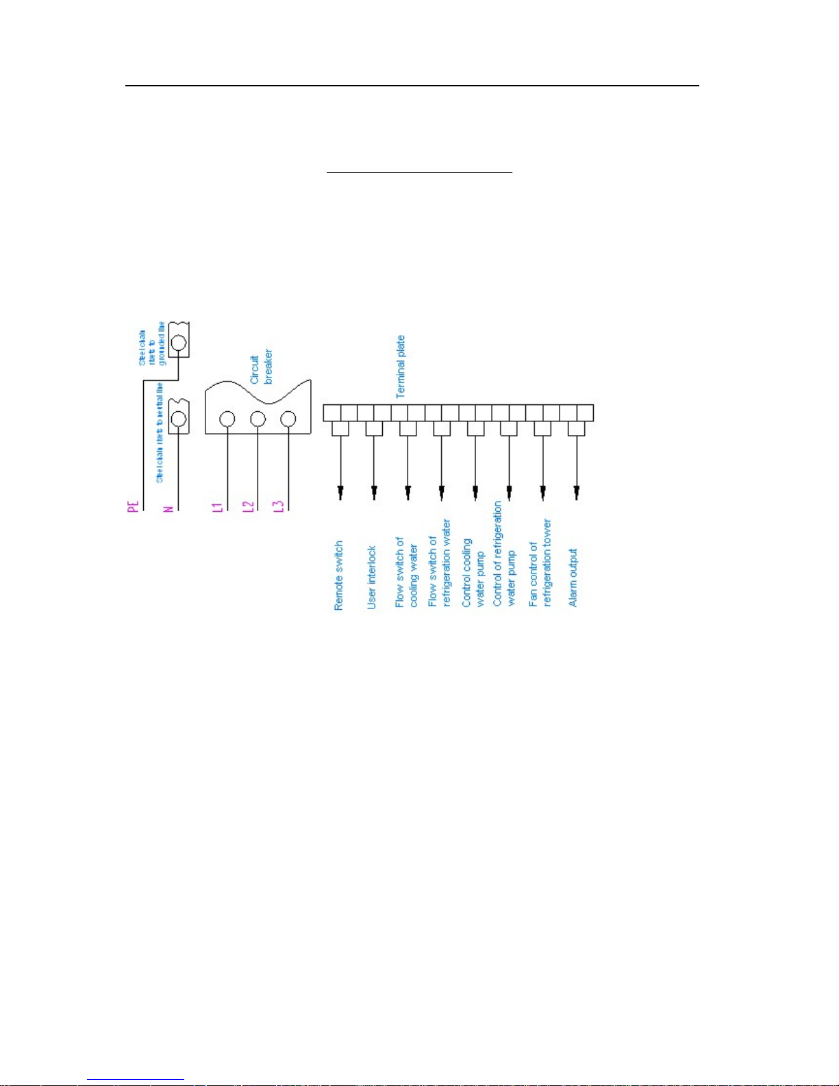
Carrying capacity of supply power cord should be higher than max operating current of unit and
takes impact of working environment into account. As for unit using duplex power supply, diameter
of two power cords should be the same.
Wiring for user is as follows:
1.Three-phase power supply respectively uses yellow, green, red, light blue and yellow/green
wire corresponding to L1, L2, L3, N and PE.
2.Communication line shouldn’t tightly rely on power cord or be laid parallel with power cord.
3.Confirm phase sequence of power cord when installing power cord. Firmly press connection
terminal, then connect it to power supply terminal of unit. It is must be tightened, otherwise,
disastrous results such as unit failure or even fire hazard will be caused by superheat.
4.After installing power cord, it is a must to carefully check according to wiring diagram and
supply power after ensuring correct wiring.
5. Grounding requirements
Unit must be reliably grounded and wire of earth line is usually selected according to the
following requirements:
Page 31
Flooded Type Water Cooled Screw Chiller Technical M
anual
28
Sectional area of Earth Line
Sectional area of phase wire for device “S”(mm2) Earth line (mm2)
S≤16 S
16<S≤35 16
35<S≤400 S/2
400<S≤800 200
S>800 S/4
5 Commissioning of Unit
5.1 Preparation before Commissioning
Step 1: Check wiring of power supply and electrical system
Before initial startup, check if distribution capacity complies with power of the unit and if
diameter of power cable can stand max working current of main unit.
Check is power system complies with the unit; power system of the unit: three-phase five-line
system (L1, L2, L3, N, PE, 380V 3N~/50Hz), check if phase sequence is correct.
Check power supply line of compressor and retighten if it is loose. Otherwise, A/C contactor or
even the compressor will be damaged.
Measure with megohmmeter the insulation resistance of earth line at phase line end of power
supply, and measure the insulation resistance of earth line for motor winding; resistance
shouldn’t be less than 10MΩ; if the insulation resistance of earth line at compressor winding
end is more than 2MΩ, check if earth line is correctly and reliably installed;
Check if power cord meets capacity requirement.
Check if circuit breaker is installed on power cord of supply unit.
Check external wiring (wiring of target flow switch, interlocking control of water pump)
according to wiring diagram and check if inside and outside, especially each wiring joint, of
electrical cabinet are clean without sundries.
Before starting, check if external system of unit meets condition of startup. As for water pump
controlled externally, it’s necessary to firstly open water pump before starting main unit.
Conduct trial operation when main loop disconnects and check if electrical components act
normally.
Page 32
Flooded Type Water Cooled Screw Chiller Technical M
anual
29
Normal startup sequence of star-delta: switch on power supply; press startup key of unit;
three minutes later, main and star A/C contactor attract; after 2-5s, star A/C contactor
disconnects; angle A/C contactor attracts; unit begins to start at startup load and load
gradually.
Normal startup sequence of shunt winding: switch on power supply; press startup key of unit;
three minutes later, main contactor attract; after main contactor attracts for 0.5s, unit begins to
start at startup load and load gradually.
Before starting, check if external system of unit meets condition of startup (if refrigeration water
pump and cooling water pump of system are in mode of external control or main linkage; as
for external control, it’s necessary to firstly open water pump before starting main unit)
(enclosed with checklist)
Step 2: Check compressor and refrigeration pipeline
All refrigerant valves (angle valve at outlet of condenser, intake and discharge cut-off valve of
compressor, cut-off valve at connection of high & low pressure switch of compressor) in refrigeration
system should be opened to make refrigeration system smooth;
Check if oil level in compressor is normal; normal oil level of compressor is usually in the
middle of sight glass;
Check if protection setting value (shown below) of high and low pressure is normal;
Item Setting value
Protection value of high pressure 1.8MPa
Protection value of low pressure 0.35MPa
Protection value of difference between high and low pressure 0.4 MPa
Check if pipeline system of unit is damaged during transportation and handling;
Check if there is pressure in refrigerating system and if there is leaking point of refrigerant;
Step 3: Check Water System
Check if pipeline of cooling and refrigeration water is cleanly flushed and if there are sundries
at the connection part of cooling and water pool with outside, ensure there are no sundries
and foreign matters in pipe.
Check if pressure gauge and thermometer at water side are correctly connected. Pressure
gauge should be installed vertically to the water pipe. Thermometer should be installed in
Page 33

Flooded Type Water Cooled Screw Chiller Technical M
anual
30
such as a way to ensure its sensing probe directly inserts into water pipeline.
Check if flow switch at outlet side of refrigeration and cooing water is correctly installed, and
confirm flow switch and control cabinet are correctly wired.
Inch refrigeration and cooing water pump and check rotation direction of water pump. Correct
rotation direction of water pump should be clockwise, otherwise retest wiring of water pump.
Start refrigeration and cooing water pump and enable water flow to circulate. Check if there is
leakage of water pipeline, such as obvious water leakage and dripping.
Conduct trial operation on cooling and refrigeration water pump. Observe if water pressure is
stable. Observe pressure gauge at inlet and outlet of water pump, there is slight change on
reading of pressure gauge and difference between inlet and outlet pressure when water pressure
is stable. Observe if operating current of water pump is within the range of rated operating current.
If there is great discrepancy compared with rated operating current, check if the resistance of
system is too high, and eliminate system failure until actual operating current meets requirement.
Check if makeup device of cooling tower and expansion water tank is smooth and if automatic
discharge valve in water system can automatically discharge. As for manual discharge valve,
open discharge valve of refrigeration water pipeline and cooling water pipeline, and evacuate
air from pipe.
Adjust water flow and check if water pressure drop of evaporator and condenser meets
operation requirement set by unit. In other words, inlet & outlet pressure of refrigeration water
and cooling water of unit should be at least above 0.2MPa.
Step 4: Check A/C end (coil pipe of fan)
Check if all power supplies of indoor fan coil pipe and control wirings are correct, if fan rotation
is set flexibly.
Check if all stop valves and flow adjusting valves at inlet and outlet of fan coil pipe are open.
Check if air in coil pipe of fan is evacuated completely. If there is air in coil pipe, abnormal
noise can be heard. In this case, it’s necessary to rotate manual discharge valve to exhaust
air ad tightly close discharge valve until there is steady water flow
Check if there are sundries deposited in stagnant water pan of fan coil pipe.
5.2 Operation of Unit
Step 1: Before starting unit, it’s required to preheat crankcase of compressor at eight hours;
Step 2: Properly open coil pipe of indoor fan;
Page 34

Flooded Type Water Cooled Screw Chiller Technical M
anual
31
Step 3: Firstly start refrigeration water pump, then start cooling water pump, listen if there is
abnormal sound from water pump and observe if water pressure is within setting range (pressure
difference of inlet and outlet water is no less than 50KPa). Flow switch protection indicates ultralow
flow of water pump, which requires finding out cause and solving the problem;
Step 4: After starting (add compressor and observe change of high & low pressure), compressor
operates from 25% energy to 50% energy; then compressor performs upload control according to
temperature; when temperature is lower than setting value, compressor offloads. During this
process, it’s necessary to measure if operating current of compressor is within designated range of
nameplate, observe if there is abnormal sound, record parameters such as high & low pressure,
inlet & outlet water temperature, operating current.
Page 35
Flooded Type Water Cooled Screw Chiller Technical M
anual
32
Chapter III Operation and Maintenance
1. Operation Instruction
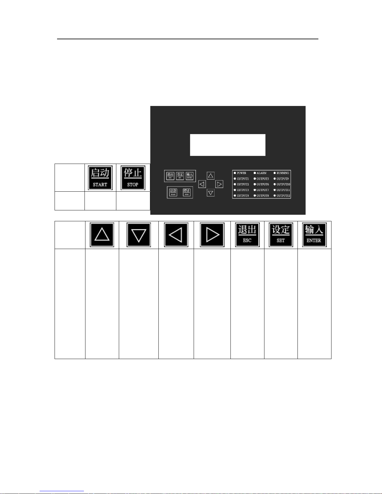
1.1Button Instruction of Wired Controller
Button
Function
1. start
button
1. Stop
button
Button
Function
1. Switch
picture
upwards.
2. Switch
numerical
value.
1. Switch
picture
downwards.
2. Switch
numerical
value.
1. Switch
picture
leftwards.
2. Return
to
navigation
menu.
3. Move
cursor of
numerical
value
field.
1. Switch
picture
rightwards.
2. Move
cursor of
numerical
value field.
Exit
numerical
value
setting or
function
selection
state.
Enter into
numerical
value
setting or
function
selection
state.
After
modifying
numerical
value,
press this
key to
confirm
input.
Page 36
Flooded Type Water Cooled Screw Chiller Technical M
anual
33
1.2 Operation Instruction of Wired Controller
1.2.1 Setting of Parameter
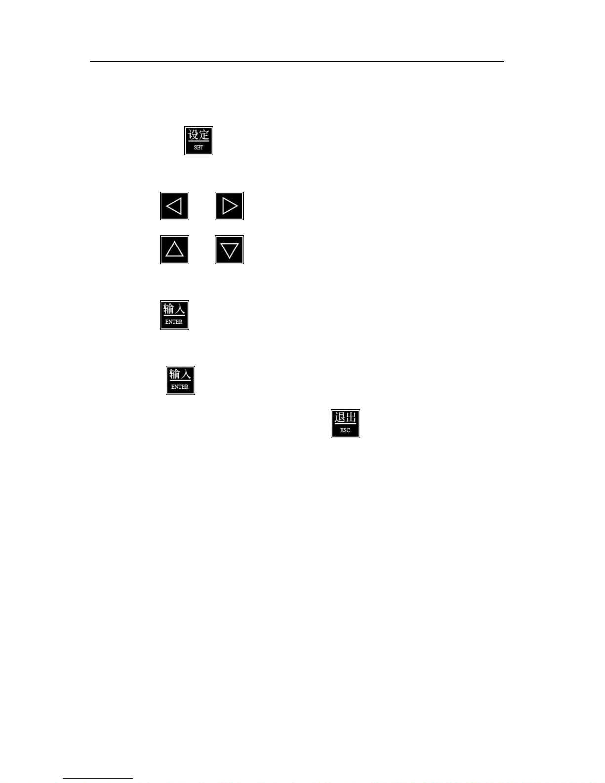
First enter into picture whose parameters need to be adjusted.
Then press . Usually, parameter consists of several digits. It’s allowed to select any
parameter to modify.
Press and to select digit of numerical value.
Press and to respectively increase and decrease numerical value within
0~9.
Press to confirm modifying numerical value of this field and automatically switch to
next field of parameter. If it’s unnecessary to modify numerical value of this field, directly
press to switch to next field.
When the whole parameter is modified, press
to exit setting state.
1.2.2 Description of Operating Picture
Classification of man-machine picture: It can be divided into three classes by class authority
permission that is managed by third-class password.
¾ Class-1 picture: user picture, which can be accessed without password;
¾ Class-2 picture: picture of Preferences, which can be accessed by using class-2 or class-3
password and maintenance parameter can be modified;
¾ Class-3 picture: picture of Unit setting, which can be accessed by class-3 or super
password and system parameter can be modified;
Design of man-machine picture:
Control program of this version is single/dual unit cooling program, which can only display
corresponding picture according to operating mode of unit.
For example: if single control mode is selected, control parameter and display picture of dual unit
will be concealed.
Page 37
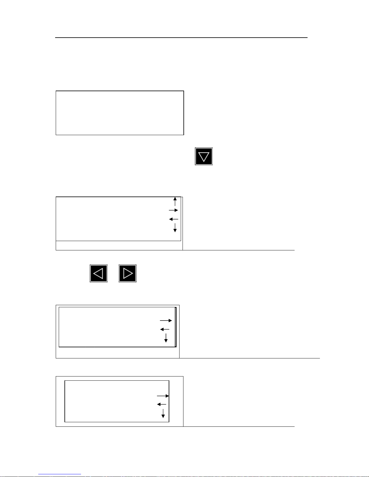
Flooded Type Water Cooled Screw Chiller Technical M
anual
34
Note: The following pictures are subject to modification without notice. Actual pictures shall
apply.
1.2.2.1 Description of Main Operating Picture
After starting, controller displays welcome picture as follows firstly.
When welcome picture is displayed, by pressing will enter into picture of main menu
respectively.
1. Main Display Picture
Left half part of main menu picture
prompts main contents under this menu;
right half part displays main menus for
upward, downward, leftward and
rightward switching.
Fig. 1
By pressing or key, it will enter into another six main menu pictures:
2. I/O State Display Picture
Display current state of input/output contact of
system.
Fig. 2
3.Alarm Picture
Display alarm information for
abnormality of unit operation.
Fig. 3
Flooded Chiller
WELCOME
AUKS Central Air Conditioning
System VX.XX ProgramVX.XX
Home page
Main screen I/O status
User Setting
Detail
I/O status Alarm
Main screen
Detail
Alarm display Unit setting
I/O status
Detail
Page 38
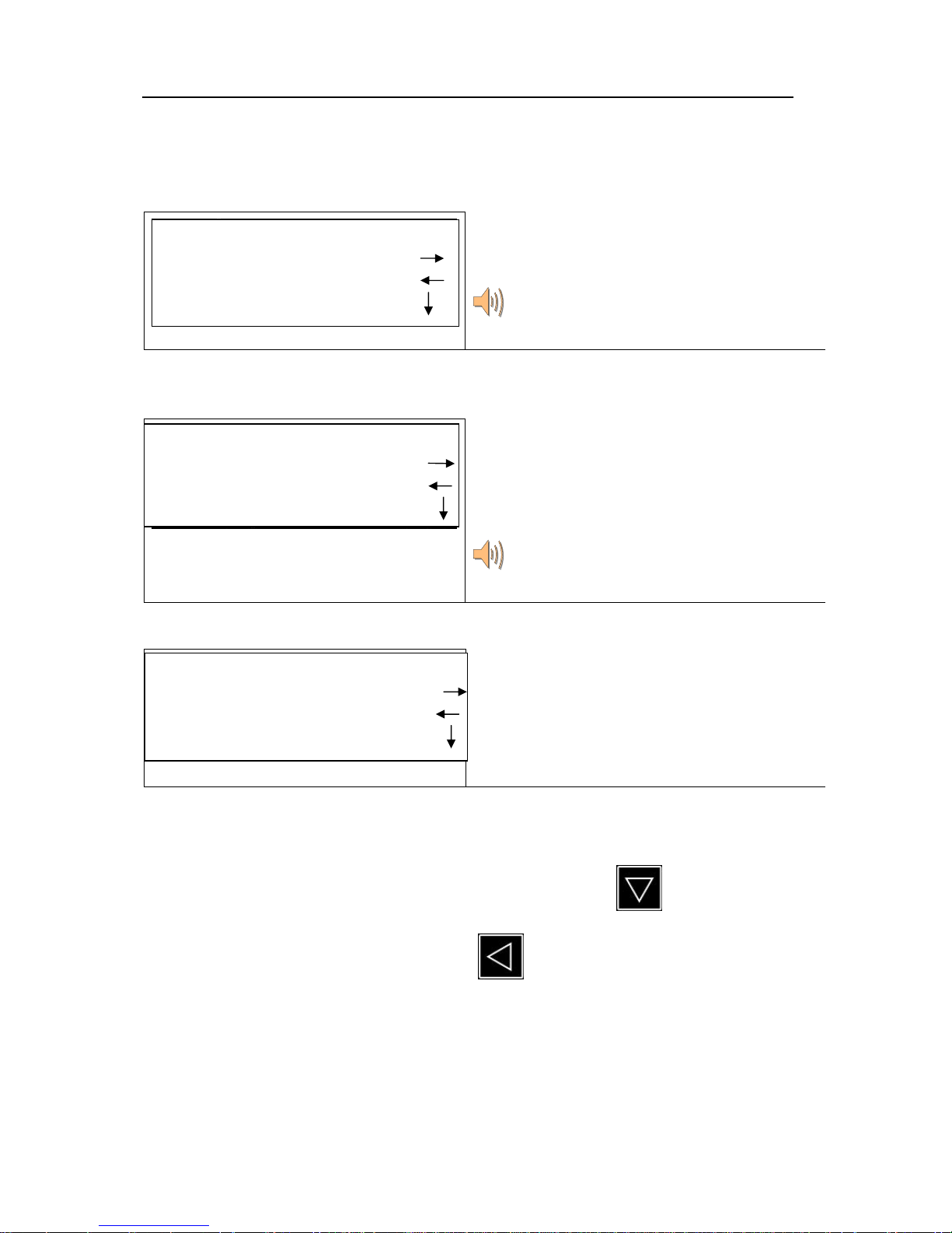
Flooded Type Water Cooled Screw Chiller Technical M
anual
35
4.Factory Setting Picture
This page can be switched to picture of next level
by using third-class password and then operating
parameters of unit can be set.
Change is only allowable for professional
maintenance personnel!
Fig. 4
5. Maintenance Setting Picture
This page can be switched to picture of next level
by using second-class password. Then system
parameters including selection of single & dual unit
system, temperature adjustment, adjustment of
operating hours and parameter backup can be set.
Change is only allowable for professional
maintenance personnel!
Fig. 5
6.User Setting Picture
It can directly enter into picture of next level to set
service parameters, adjust system time and set
automatic ON/OFF function.
Fig. 6
1.2.2.2 Description on Parameter and State Inquiry Pictures
1. Main screen (when it displays main display picture, pressing will respectively enter
into the following pictures and pressing on each picture will switch back to main
picture):
Unit setting Preferences
Alarm
Detail
Preferences User Setting
Unit setting
Detail
User Setting Main screen
Preferences
Detail
Page 39
Flooded Type Water Cooled Screw Chiller Technical M
anual
36
Date xxxx/xx/xx Time xx:xx:xx
CHW in XX.X℃
CTW in XX.X℃
Operation Prompt Operation Prompt
1. Display system time.
2. Current page displays real-time outlet water temperature
a
inlet water temperature.
3. Prompt real-time information of system operation.
Fig. 1
Display relevant operating parameters of unit 1.
Fig. 2
Display relevant operating parameters of unit 2.
Fig. 3
Display pressure value of unit 1.
Fig. 4
Display pressure value of unit 2.
Fig. 5
CHW out XX.X℃
CTW out XX.X℃
1# exhaust XX.X℃
1# suction XX.X℃
2# exhaust XX.X℃
2# suction XX.X℃
1# pressure Inquiry
High pressure X.XXMPa
Low Pressure X.XXMPa
1# oil pressure X.XXMPa
2# pressure Inquiry
2# oil pressure X.XXMPa
Page 40
Flooded Type Water Cooled Screw Chiller Technical M
anual
37
Display operating hours and startup times of unit 1.
Fig. 6
Display operating hours and startup times of unit 2.
(dual-unit system only)
Fig. 7
1. Display current control mode of unit.
2. Display operating hours of water pump.
3. Display current opening of expansion valve.
Fig. 8
3. Alarm Display Picture:
When alarm picture appears, pressing
will enter into the following pictures:
When system sends alarm, this picture will pop up
automatically, display alarm content and record time.
Fig. 3
Display historical record of alarm and record
alarm content, date and time of occurrence (there
are twenty alarm records totally which are twenty
latest records).
Note: 1/20 refers to the first record out of twenty
records.
1# running XXXXXXX Hours
1# start-up XXXXXXX Times
2# running XXXXXXX Hours
2# start-up XXXXXXX Times
Control mode Site control /Remote Control
CTW pump running XXXXXXX Hours
CHW pump running XXXXXXX Hours
Current position XXX %
Instant alarm display picture
Alarm information
DateXXXX/XX/XX TimeXXXX/XX/XX
Alarm Record 1/20
Alarm information
DateXXXX/XX/XX TimeXXXX/XX/XX
Page 41
Flooded Type Water Cooled Screw Chiller Technical M
anual
38
Fig. 4
The second record out of twenty historical alarm
records.
(The same below, omitted)
Fig. 5
1.2.2.3 Preferences of Unit
When this menu appeatrs, pressing will enter password prompt picture and inputting correct
password will enter into the following pictures:
Service setting of unit 1 and unit 2: it is used to
select the start of unit 1 or unit 2. If nonuse is set,
the unit won’t start even startup conditions of this
unit are meet.
Fig. 1
1. Temp drop rate: it is used to set velocity and
temperature drop and judge loading and
unloading of unit;
2. Temp gather: it is used to set temperature
sampling cycle;
3. Temp range: it is used to set temperature of
water return; temperature of water return
plus control temperature of water return is
the reset temperature of unit;
4. Alarm recording: if the same serious failure
occurs three times within 24 hours, unit will
be locked; this item is used to unlock serious
failure;
Fig. 2
1. Setting of Alarm Time Delay
2. when cooling water temperature diff. is
lower than set value, system will send
alarm;
Fig. 3
1# Compressor Use/Nonuse
2# Compressor Use/Nonuse
Temp drop rate X.X ℃
Temp gather XXX Sec.
Temp range X.X ℃
Alarm recording Clear/Cancel
Temp diff max XX.X ℃
Temp diff min X.X ℃
Low pressure X.XX Mpa
High pressure X.XX Mpa
Alarm Record 2/20
Alarm information
DateXXXX/XX/XX TimeXXXX/XX/XX
Page 42
Flooded Type Water Cooled Screw Chiller Technical M
anual
39
1. If high/low pressure difference is lower than set
value, system will send alarm and shut down.
2. If other actual values are higher than set value,
system will send alarm and shut down.
Fig. 4
1.If actual value of cooling water is higher than set
value, system will send alarm and shut down.
Fig. 5
Fill in positive or negative offset according to actual
measurement.
Fig. 6
Fig. 7
Exhaust overheat XXX.X ℃
Oil diff fault X.XX Mpa
Press diff fault X.XX Mpa
Oil diff delay XXX Sec.
Press diff delay XXX Sec.
CTW overheat XX.X ℃
CHW pump running XXX Min.
Unit temp correction
CHW in XX.X ℃
CTW in XX.X ℃
CHW out XX.X ℃
CTW out XX.X ℃
1# exhaust XX.X ℃
1# suction XX.X ℃
Page 43
Flooded Type Water Cooled Screw Chiller Technical M
anual
40
Fig. 8
Fig. 9
Fig. 10
1. Load parameters: load default parameter from system
program into picture;
2. Password change of maintenance personnel;
1.2.2.4 Description on the Following User Setting Pictures:
When this menu appears, pressing will enter into the following pictures:
Setting picture of water return temperature of unit
cooling.
Fig. 1
Cooling control setting
Water in temp XX.X ℃
Load parameters Load/Cancel
Password modify ****
Password again ****
Password modify successful
/Password modify failure
2# oil pressure X.XX MPa
Unit pressure correction
High pressure X.XX MPa
Low pressure X.XX MPa
1# oil pressure X.XX MPa
2# exhaust XX.X ℃
2# suction XX.X ℃
Page 44
Flooded Type Water Cooled Screw Chiller Technical M
anual
41
1. Selection of control mode: when control mode is
set as remote control, it’s possible to conduct
ON/OFF operation with external input point; in
this case, manual ON/OFF function is still
available;
2. Power failure protection function selection of
unit.
3. Status memory function is available during certain
setting time.
Fig. 2
It is used to adjust system clock. It’s possible to
change system time when system time appears under
setting mode and after entering into editing mode.
Fig. 3
After automatic ON/OFF function is enabled, unit will
automatically start and shut down according to set
time.
Note: setting of automatic ON/OFF time doesn’t judge
second (“0” second shall prevail); if both hour and
minute of ON/OFF time are set as 0000, it indicates
this function isn’t enabled.
Fig. 4
When automatic ON/OFF function is selected, priority of each setting is as follows:
Single timer > Holiday timer > Week timer. At this time, manual ON/OFF key is still effective.
It can set start time including year,
month, day, hour and minute of
holiday shutdown and shutdown time
including year, month, day, hour and
minute (it can set consecutive
holidays).
Fig. 5
Holiday timer
Start XXXX/XX/XX XX:XX:XX
Stop XXXX/XX/XX XX:XX:XX
Auto setting Enable/Cancel
Single timer Date XXXX/XX/XX
Start XX:XX:XX Stop XX:XX:XX
System time setting
Date XXXX/XX/XX
Week X
Time XX:XX:XX
Control mode Site control /Remote Control
Status memory Enable/Disable
Holding time XXXXX Hours
Page 45
Flooded Type Water Cooled Screw Chiller Technical M
anual
42
Control system can set and change
timetable of Sunday and Monday ~
Saturday. After the setting is enabled,
unit will operate according to this
timetable every week.
Fig. 6
Timing clear: clear all the setting timer
Fig. 7
2. Maintenance
2.1 Daily Maintenance
Implement startup and shutdown sequence according to required procedure every day;
Record operating parameters of unit according to certain timer interval;
Clean filter of refrigeration water and cooling water one time after unit operates for 24
hours.
Check pressure of evaporator and condenser of unit according to indication on pressure
gauge on control cabinet. Check difference between evaporation temperature and outlet
temperature of refrigeration water, difference between condensation temperature and
outlet temperature of cooling water, according to comparison table of pressure and
temperature. Pay attention to trend of change. Usually, reading of evaporation should be
0.4~0.6MPa and condensation pressure should be 1.0~1.8MPa.
Check filter dryer of refrigerant. Frosting at outlet of filter dryer indicates blockage, which is
usually followed with ultralow evaporation pressure and increased difference between
evaporation temperature and outlet temperature of refrigeration water. It’s necessary to
pay attention to timely replace filter dryer of refrigerant;
Check oil level in oil tank. Oil level is usually set at middle position of sight glass. It’s
Saturday timer
Start XX:XX:XX Stop XX:XX:XX
Timing clear Clear/Cancel
Sunday timer
Start XX:XX:XX Stop XX:XX:XX
Monday timer
Start XX:XX:XX Stop XX:XX:XX
Page 46

Flooded Type Water Cooled Screw Chiller Technical M
anual
43
necessary to timely fill refrigeration oil if oil level drops greatly;
Any shutdown failure should arouse attention and cause should be analyzed. Before
notifying AUKS customer service department, analysis based on failure help of this
manual may be conducive to the solution of problem.
2.2 Regular Maintenance
Regular maintenance includes weekly, monthly, quarterly, biannual and annual maintenance.
Customer should establish scientific and regular maintenance plan according to the following content,
and implement carefully, which will play very important role for preventing problems.
2.2.1 Weekly Maintenance
Check and analyze record table of operating parameters.
2.2.2 Monthly Maintenance
Check and analyze record table of operating parameters;
Check if set bolt of power supply wiring is loose;
Check if there is noise in each moving part of unit and if operation is set;
Check if high pressure and low pressure of cooling system is set;
Check operating current of motor and insulating resistance of unit are set;
Check if dry filter and sight glass are set; frosting at outlet of filter indicates filth blockage
in filter, which requires cleaning filter net; if there is humidity indication (red color)on
sight glass, it’s required to replace filter element;
Check if lubricating oil of compressor is set; if oil level is lower than 1/2 of sight glass, it’s
necessary to add lubricating oil; if there is filth or oil is deteriorated, it’s necessary to
replace lubricating oil, clean or replace oil filter ad replace element of dry filter;
2.2.3 Quarterly Maintenance
Check and analyze record table of operating parameters;
Check oil level of compressor;
Clean filter of evaporator and condenser water system pipeline;
When unit operates under full capacity, check temperature drop of refrigerant generated
when it passes filter dryer.
2.2.4 Biannual Maintenance
Check and analyze record table of operating parameters;
Page 47

Flooded Type Water Cooled Screw Chiller Technical M
anual
44
Conduct physical and chemical analysis on refrigeration oil to judge water content and
acidity of refrigerant in unit;
Check tightness of all electrical joints that may be loose in control cabinet, startup
cabinet and motor.
2.2.5 Annual Maintenance
Check and analyze record table of operating parameters;
Check oil level and conduct physical and chemical analysis on refrigeration oil; Replace
refrigeration oil of the same grade if oil is emulsified.
Replace filter of refrigeration oil when necessary. Maintenance personnel should check
this item.
Dismantle connecting pipe at outlet of safety valve at last once a year and check valve
body carefully to see if there is corrosion, rust, scale and leakage inside. Replace safety
valve in case of corrosion or leakage. Maintenance personnel should check this item.
Verify set value of high pressure switch of condenser and ensure high pressure switch
acts at 1.8MPa.
Check scale formation degree of pipe pass of condenser. Evaporator that connects open-
type system should also be checked. According to result of checking, it can be determined
that if cleaning cycle and treatment of water in water loop are suitable; if serious scale
formation is found, clean pipe pass. Clean heat transfer pipe at least once a year with
rotary cleaning equipment. If water is polluted, it’s necessary to clean more frequently.
Ultrahigh condensing pressure and insufficient cooling capacity of unit are usually
caused by scale in pipe or air in unit. Compare outlet temperature of cooling water with
refrigerant temperature of condenser. If the difference between them is more than 6℃,
scale may have formed in condensation pipe.
Note: during cleaning heat transfer pipe, it’s necessary to use dedicated brush to prevent
scratching and scraping pipe wall. No wire brush is allowed to use.
Maintenance personnel should detect insulation resistance among motor winding and
grounding resistance of winding.
2.2.5 Maintenance Every Three Years
Items of the above-mentioned annual maintenance and check.
Contact qualified maintenance organization such as AUKS local customer
service
Page 48

Flooded Type Water Cooled Screw Chiller Technical M
anual
45
department to conduct overall check for unit. Especially check vibration status of
compressor and ensure parts in compressor are in good conditions; conduct airtight test
on unit and check if copper pipe for heat transfer leaks; conduct non-destructive test on
main weld seams (longitudinal seam and circumferential seam of evaporator and
condenser cylinder) of pressure vessels when necessary to ensure operation safety;
check electrical operation and safety control to ensure electrical parts are in good
conditions.
Page 49
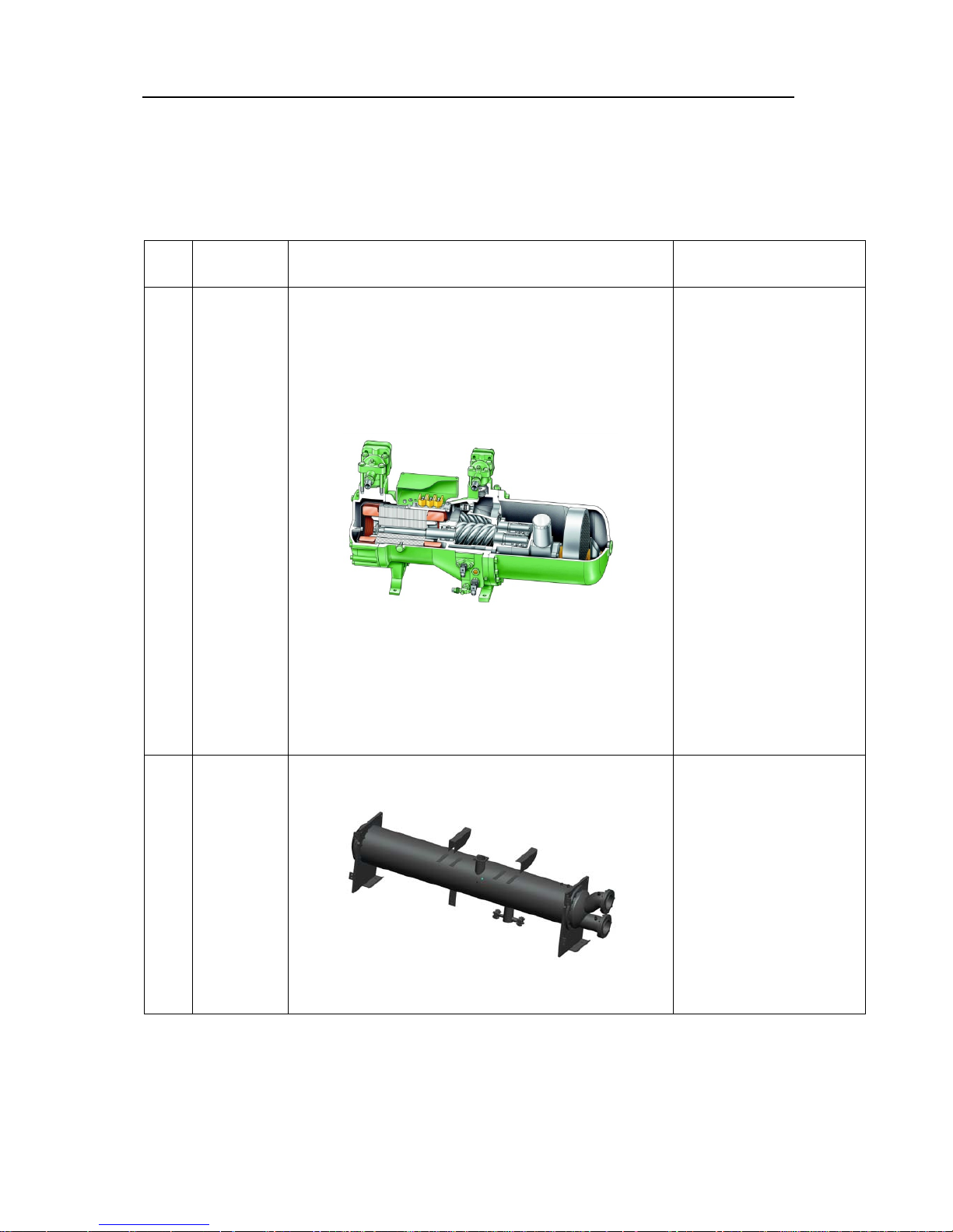
Flooded Type Water Cooled Screw Chiller Technical M
anual
46
Chapter IV After-sales Service
1. Main Parts of Unit
1.1 Main Pats of Cooling System
No.
Name of
Parts
Outline drawing and internal structural
drawing
Description
1
Screw
compressor
Compressor is used to
compress
low-temperature
low-pressure refrigerant
gas evaporated by
evaporator, make it into
high-temperature
high-pressure refrigerant
gas, then send it to
condenser and make
refrigerant to cycle.
This series product uses
semi-closed screw
compressor integrating
motor and compressor.
2
Shell and
tube
condenser
Water-cooled condenser
is used to cool
high-temperature
high-pressure refrigerant
gas discharged by
compressor and
exchange heat with
condensed (liquefied)
heat exchanger and
cooling water.
Page 50
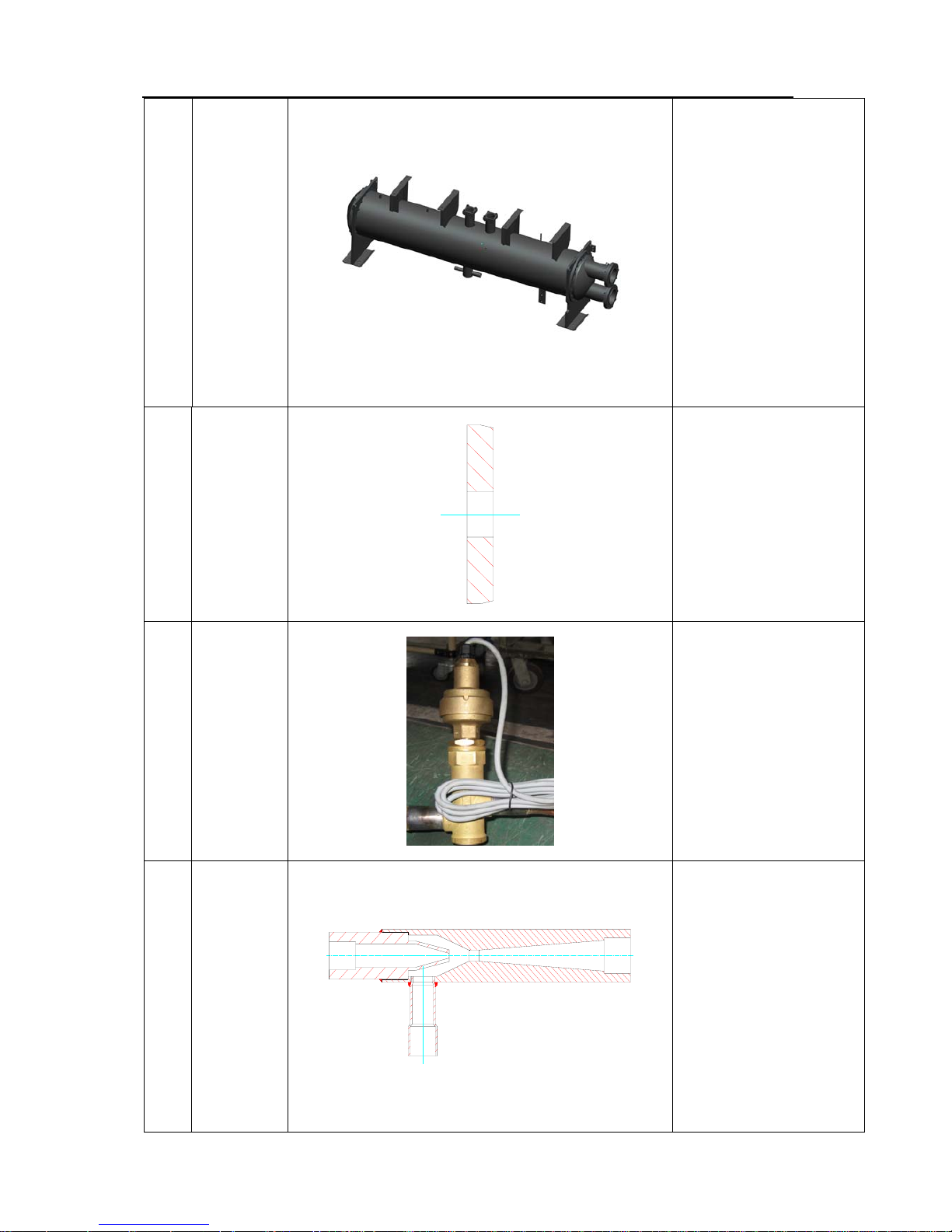
Flooded Type Water Cooled Screw Chiller Technical M
anual
47
3
Shell and
tube
evaporator
Evaporator is used to
evaporate low pressure
liquid refrigerant from
throttling parts after the
refrigerant exchanges
heat with refrigeration
water in evaporator.
4
Orifice
plate
(throttling
part)
Orifice plate is used to
generate pressure
difference by utilizing
change of orifice diameter
and control flow &
pressure refrigerant.
5
Electronic
expansion
valve
(throttle
part)
Electronic expansion
valve is used to change
throttle flow and control
refrigerant flow and
pressure by controlling
step motor.
6 Injector
Injector is used to inject
oil and refrigerant in
evaporator to return air
pipe by using
high-temperature
high-pressure gas and
liquid as injection source.
Page 51
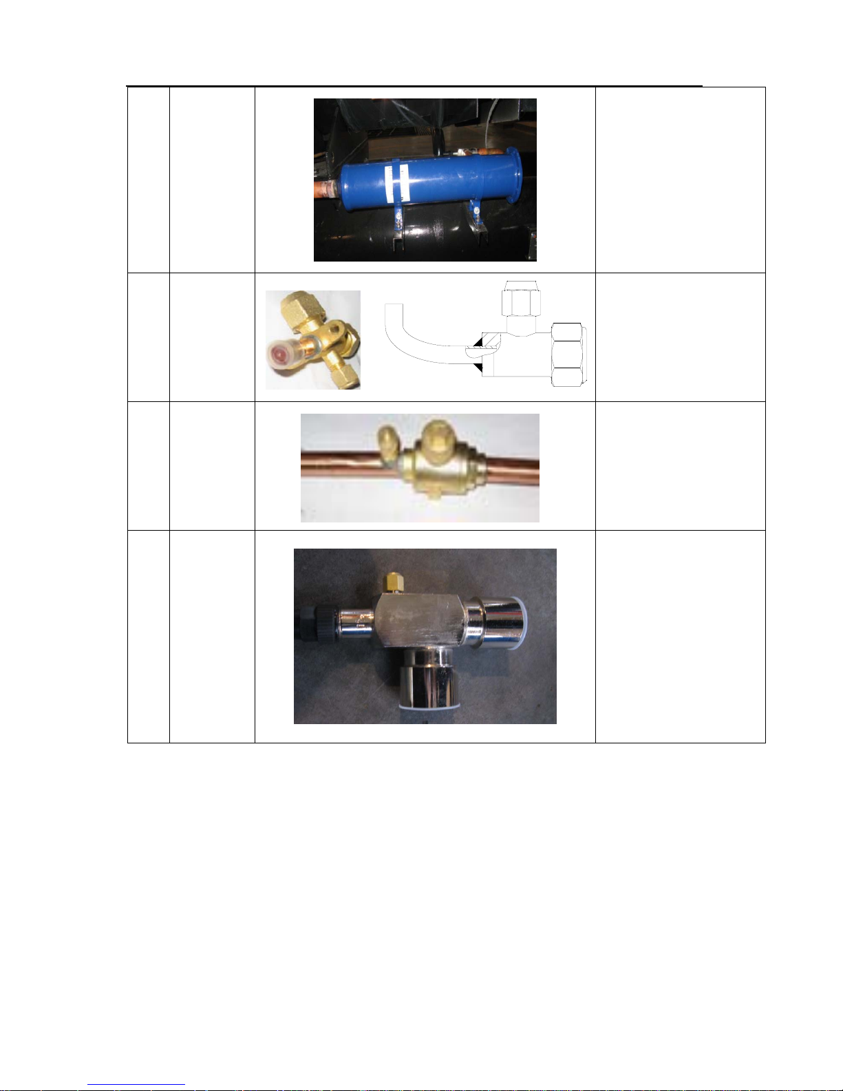
Flooded Type Water Cooled Screw Chiller Technical M
anual
48
6
Dry filter
cartridge
Dry filter cartridge is used
to filter and dry refrigerant
by installing filter element
usually on liquid pipe and
filter element can be
removed.
7 Stop valve
Stop valve is used to cut
off or dredge refrigerant,
which is only applicable to
full opening and full
closing and can’t be used
to adjust and throttle.
8 Globe valve
Globe valve is used to cut
off or dredge refrigerant,
which has throttling
function partially.
10
Angle-type
cutoff valve
Angle-type cutoff valve is
used to cut off or dredge
refrigerant, which is only
applicable to full opening
and full closing, and is not
allowed to adjust and
throttle.
Page 52
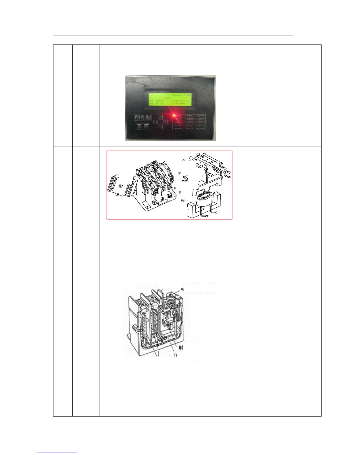
Flooded Type Water Cooled Screw Chiller Technical M
anual
49
1.2 Main Parts of Electrical System
No.
Name
of
parts
Outline drawing and internal structural
drawing
Description
1
Contr
oller
Controller is used to
control movement of relay
through program, switch
on and off each part of
unit according to external
conditions such as
temperature and
pressure, and realize
automatic control of unit.
3
A/C
contac
tor
When electromagnetic coil of
contactor isn’t powered on,
reacting force of spring and
deadweight of armature core
keep main contact at
disconnected position. When
electromagnetic coil is
powered on, electromagnetic
force attracts armature
towards static iron core by
overcoming reacting force of
spring, which drives main
contact to close, switches on
circuit. AUKSiliary junction
acts accordingly.
4
Therm
al
relay
Thermal relay is usually
composed by overcurrent
element of bimetal. When
current is too high, bimetal
will generate heat that makes
it deform, offset and pry up
protective contact. Control
loop of contactor disconnects
and power of main circuit
fails. Then,
temperature drops, bimetal
cools, circuit is switched on
again. However,
self-insurance control loop of
main circuit has disconnected
and it’s necessary to press
“Start” button again to start it.
Normal open main contact
Normal closed AUKSiliary contac
t
Normal open AUKSiliary contact
Armature
Sucking coil
Iron core
Arcing chamber
Reset rod
Setting knob of current
Thermal element
Contact
Driving push rod
Page 53
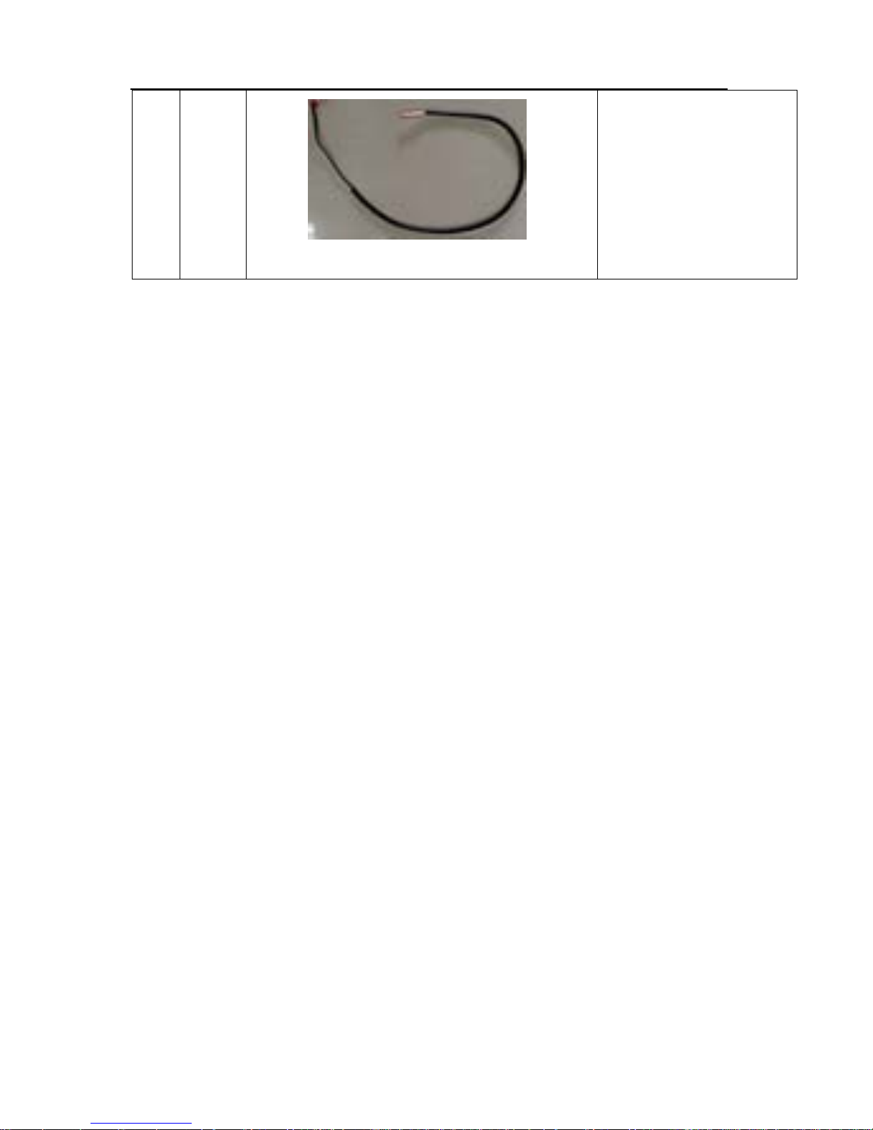
Flooded Type Water Cooled Screw Chiller Technical M
anual
50
5
Senso
r
It is a kind of electrical
element used to detect
temperature and pressure,
whose physical
characteristics vary with
change (e.g. resistance of
NTC varies with change of
temperature) of temperature
and pressure.
2. Function and Control of Unit
2.1 Function and Control of Unit
Manually ON/OFF
By pressing “start” button on controller, unit starts after 5s; when it’s necessary to stop operation, by
pressing “stop” button, unit shuts down.
Timely ON/OFF
Users can set ON/OFF time in for of year, month and day, or set ON/OFF time for a week or set
ON/OFF time for every day. If user sets ON/OFF time, unit automatically starts and shuts down at the
set time.
ON/OFF Control Process of Unit
Electrify control cabinet and preheat oil heater of compressor. unit can be started after oil
heater is preheated at least eight hours;
During startup process, firstly start refrigeration/cooling water pump; after time is delayed for 60S,
unit begins to start. If water temperature exceeds set value plus 2℃, compressor starts; Compressor
operates at 25% at first and switches to operate at 50% 30S later, then loads according to
temperature.
In case of shutdown, unit unloads to 25% and shuts down after operating for 30 seconds. Stop
cooling and refrigeration water pump after time is delayed for 180S.
If cooling water pump isn’t interlocked with refrigeration water pump, it’s required to stop cooling and
refrigeration water pump after compressor stops and time is delayed for 180S in case of shutdown.
Page 54
Flooded Type Water Cooled Screw Chiller Technical M
anual
51
2.2 Loading/Unloading Process Control of Unit
When shutdown time of compressor exceeds set time of 300S and return temperature of
cold water exceeds set value plus 1℃, compressor starts. When starting, it automatically
selects and makes head with the shortest time start firstly.
Unit operates by loading when return temperature of cold water is in loading area and
speedup loading area.
Unit unloads when return temperature of cold water is in unloading area. All compressors
stop operation if return temperature of cold water reaches emergency shutdown area.
Time interval of previous ON/OFF and next ON/OFF of each heads is at least five
minutes.
2.3 Protection Function
Flow Protection of Chilled Water Pump
Prerequisites for flow protection of refrigeration water pump:
① After refrigeration water pump operates for 30S in case of set operation or power-on initial
startup;
② ON/OFF state reflected by flow of refrigeration water pump is OFF state;
Emergency
Shutdown Area
Unloading Area Stability Area Stability Area loading Area Speedup Loading
Area
T
set
=12
Page 55

Flooded Type Water Cooled Screw Chiller Technical M
anual
52
③ Abnormal tie delay of water flow reaches 5S;
Conditions for exiting flow protection of refrigeration water pump:
Manually reset and set flow feedback of refrigeration water pump.
Flow Protection of Cooling Water Pump
Prerequisites for flow protection of cooling water pump:
① After cooling water pump operates for 30S in case of set operation or power-on initial startup;
② ON/OFF state reflected by flow of refrigeration water pump is OFF state;
③ Abnormal tie delay of water flow reaches 5S;
Conditions for exiting flow protection of cooling water pump:
Manually reset and set flow feedback of cooling water pump.
High Pressure Protection
Prerequisites for high pressure protection:
① Unit is under operation or standby state;
② Pressure of high pressure sensor is higher than [set value of overhigh protection for high
pressure] maintenance (second-class);
③ Abnormal time delay reaches 3s;
Conditions for exiting high pressure protection:
Manually reset and lock it after three times of accumulated protection within 48 hours.
Temperature Difference Protection of Insufficient Water Flow
Prerequisites for temperature difference protection of insufficient water flow:
① Unit is under operation state;
② Inlet and outlet water temperature difference of condenser is no less than 8℃ and abnormal
time delay reaches 1min.
Press “shutdown due to serious failure” to enter into standby state after entering into
temperature difference protection of insufficient water flow.
Conditions for exiting temperature difference protection of insufficient water flow:
Manually reset and lock (password is controlled by maintenance personnel) it after three
times of accumulated protection within 48 hours.
Temperature Difference Protection under Too Large Water Flow
Prerequisites for temperature difference protection under too large water flow:
Page 56

Flooded Type Water Cooled Screw Chiller Technical M
anual
53
① After compressor operates for 10min;
② Inlet and outlet water temperature difference of condenser is no more than 2℃ and
abnormal time delay reaches 1min.
Conditions for exiting temperature difference protection under too large water flow:
Manually reset and lock (password is controlled by maintenance personnel) it after three times of
accumulated protection within 48 hours.
Low Pressure Protection
Prerequisites for low pressure protection:
① Unit is under operation or standby state;
② Pressure of air suction pressure sensor is lower than [0.39MPa] set value of ultralow protection
for low pressure] maintenance (second-class), and abnormal time delay reaches 10S;
Conditions for exiting low pressure protection:
Manually reset; pressure of air suction pressure sensor is higher than ultralow protection of low
pressure plus 0.15;
Overload Protection of Compressor
Prerequisites for overload protection:
① Unit is under operation or standby state;
② Overload switch is under On state and protection time delay reaches 3s;
Conditions for exiting overload switch protection:
Manually reset; overload switch is restored to OFF state.
Anti-freezing Switch Protection
Prerequisites for anti-freezing switch protection:
① Unit is under operation or standby state;
② Magnetic anti-freezing switch (4℃) disconnects.
Conditions for exiting anti-freezing switch protection:
Manually reset;
Ultralow Outlet Water Temperature Protection (no alarm information)
Prerequisites for ultralow outlet water temperature protection:
○1 Unit is under operation or standby state;
○2 Outlet water temperature is no more than 5℃.
Page 57

Flooded Type Water Cooled Screw Chiller Technical M
anual
54
Press “unloading & shutdown” flow to enter into standby state after entering into ultralow outlet
water temperature protection.
Conditions for exiting ultralow outlet water temperature protection:
Water return temperature is no less than [set water return temperature of refrigeration water] plus 2;
manually reset.
Ultrahigh Discharge Temperature Protection
Prerequisites for ultrahigh discharge temperature protection:
① Compressor works;
② Discharge temperature T
discharge
is higher than [ultrahigh discharge temperature]
(second-class password).
Conditions for exiting ultrahigh discharge temperature protection:
Lock it after manually reset three times and accumulated protection three times within 48 hours
(discharge temperature “T
discharge
“ is no more than [ultrahigh discharge temperature] minus
25℃ );
Temperature Sensor Failure Protection
Prerequisites for temperature sensor failure protection:
① Sensor is under open circuit or short circuit;
Conditions for exiting sensor failure protection:
Manually reset; setting of corresponding temperature sensor is restored;
Pressure Sensor Failure Protection
Prerequisites for failure protection of pressure sensor:
① Pressure sensor is under open circuit or short circuit and time is delayed for 3s;
Conditions for exiting high pressure sensor:
Manually reset and failure is eliminated.
Oil Pressure Difference Protection (high pressure – oil pressure)
Prerequisites for oil pressure difference protection:
① Compressor works (shield in case of shutdown);
② Oil pressure difference is higher than [0.2mpa], and time delay protection [time delay of oil
pressure difference protection] reaches 40S;
Conditions for exiting oil pressure difference protection:
Page 58

Flooded Type Water Cooled Screw Chiller Technical M
anual
55
Manually reset and lock (password is controlled by maintenance personnel) it for three times; oil
pressure difference switch is under ON state.
High/Low Pressure Difference Protection (high pressure – low pressure)
Prerequisites for high/low pressure difference protection:
① Compressor works (shield when it is started less than 2min or in case of shutdown);
② High/low pressure difference is less than [0.4mpa], time delay protection [time delay of
high/low pressure difference protection] reaches 40S;
Conditions for exiting high/low pressure difference protection:
Manually reset; switch of high/low pressure difference is under ON state.
Oil Level Protection of Compressor
Prerequisites for oil level protection:
① Compressor works (shield in case of shutdown);
② Switch of oil level protection disconnects and time delay protection reaches 30S;
Conditions for exiting oil level protection:
Lock (password is controlled by maintenance personnel) it one time and oil level switch is under
ON state.
Ultrahigh Temperature Protection of Cooling Water
Prerequisites for ultrahigh temperature protection of cooling water:
Outlet temperature of cooling water is no less than 40℃ [ultrahigh temperature of cooling
water];
Conditions for exiting temperature protection of cooling water:
① Outlet temperature of cooling water is no more than 40℃ [ultrahigh temperature of
cooling water] minus 7℃ (automatic reset) ;
② Protectively lock it three times (password is controlled by maintenance personnel).
3. Failure Analysis and Solution
3.1 Analysis and Solution of Failure with Failure Code
Page 59
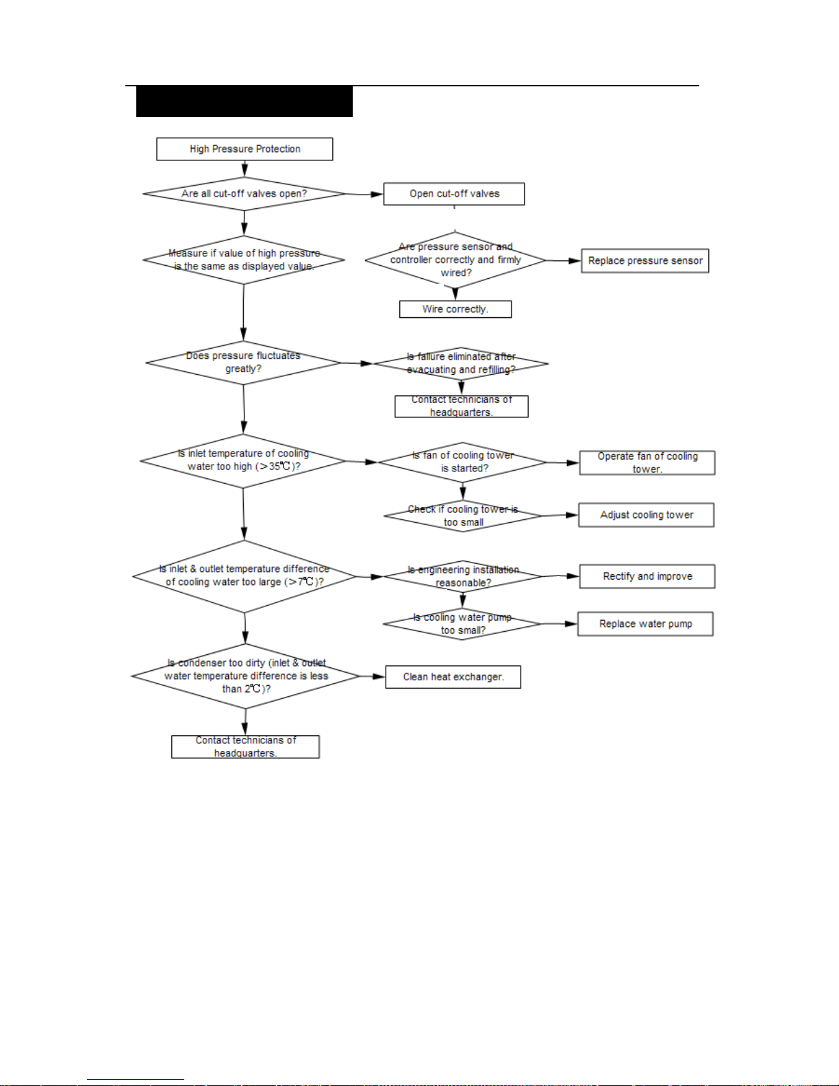
Flooded Type Water Cooled Screw Chiller Technical M
anual
56
High Pressure Protection
NO
→
NO
NO
NO
NO
NO
NO
NO
NO
YES
YES
YES
YES
YES
YES
YES
YES
YES
NO
YES
YES
Page 60
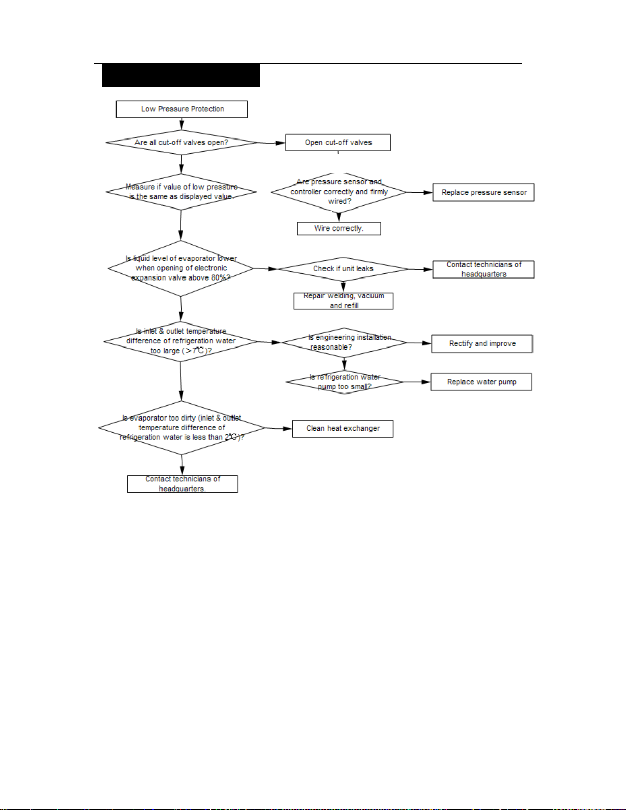
Flooded Type Water Cooled Screw Chiller Technical M
anual
57
Low Pressure Protection
→
YES
YES
YES
YES
NO
YES
YES
YES
YES
YES
NO
NO
NO
NO
NO
NO
NO
Page 61
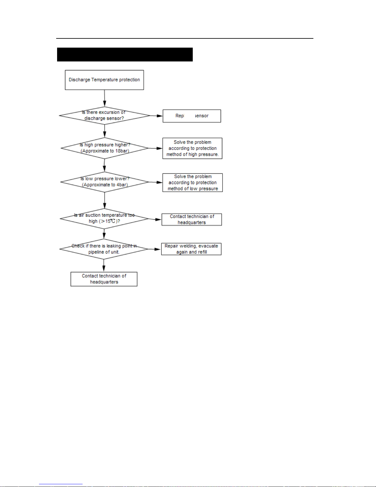
Flooded Type Water Cooled Screw Chiller Technical M
anual
58
Discharge Temperature Protection
NO
NO
NO
NO
NO
NO
YES
YES
YES
YES
YES
Page 62
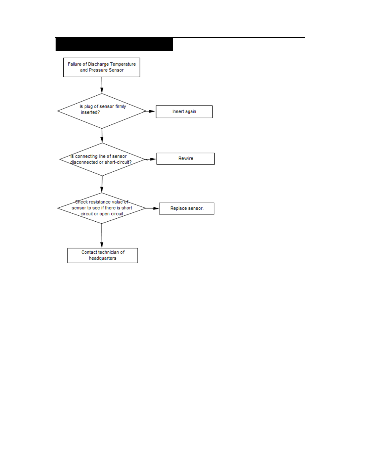
Flooded Type Water Cooled Screw Chiller Technical M
anual
59
Failure of Temperature Sensor
NO
YES
YES
YES
NO
NO
Page 63
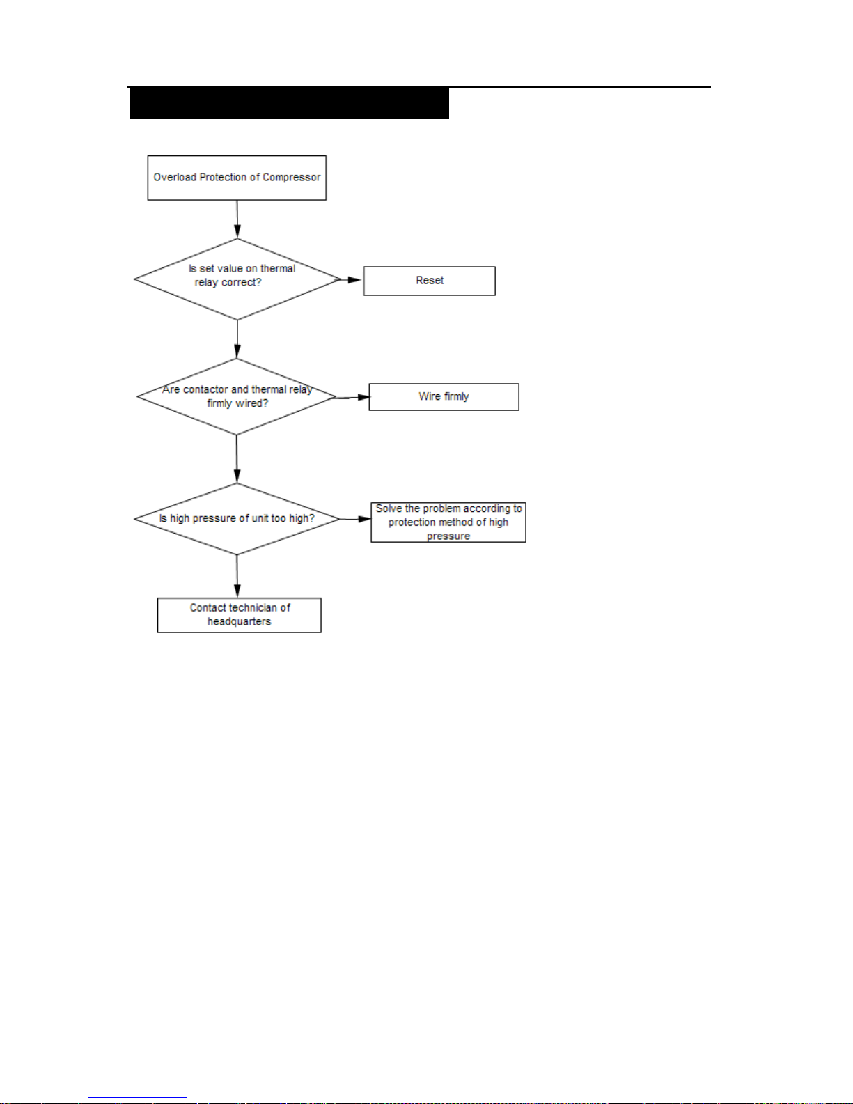
Flooded Type Water Cooled Screw Chiller Technical M
anual
60
Overload Protection of Compressor
NO
NO
NO
YES
YES
YES
Page 64
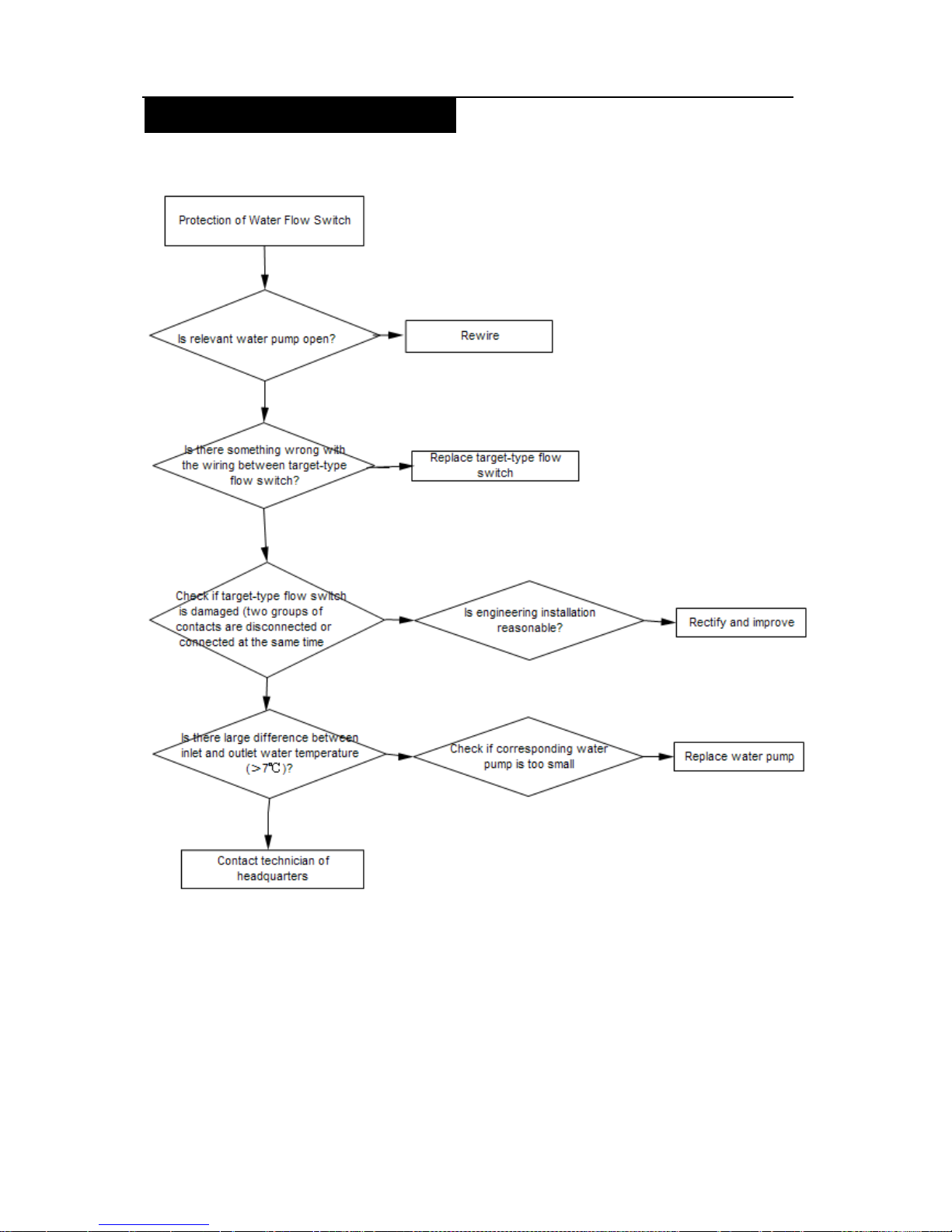
Flooded Type Water Cooled Screw Chiller Technical M
anual
61
Protection of Water Flow Switch
S
YES
YES
YES
YES YES
NO
NO
NO
NO
NO
Page 65
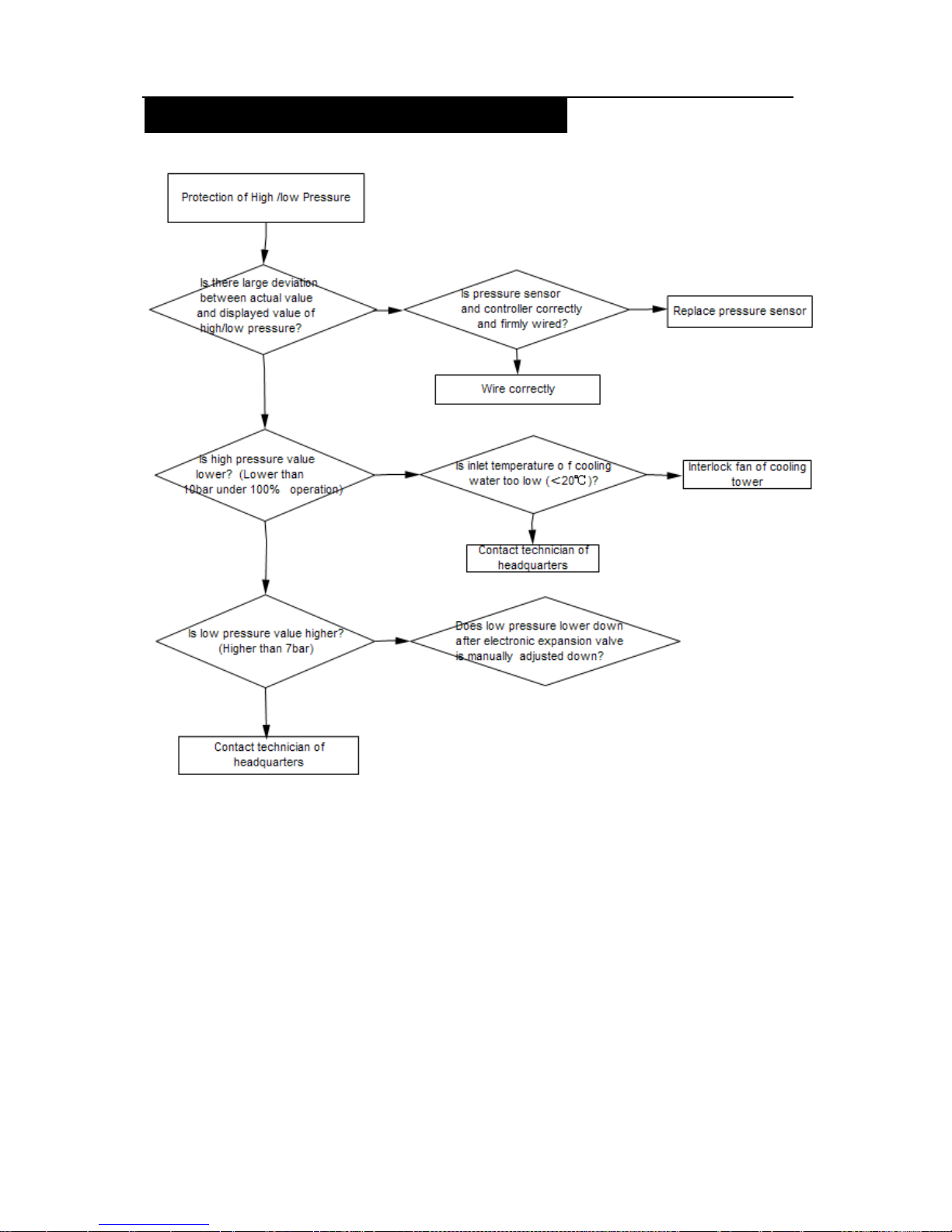
Flooded Type Water Cooled Screw Chiller Technical M
anual
62
Protection of High/Low Pressure Difference
NO
NO
NO
NO
YES YES
YES
YES
YES
Page 66
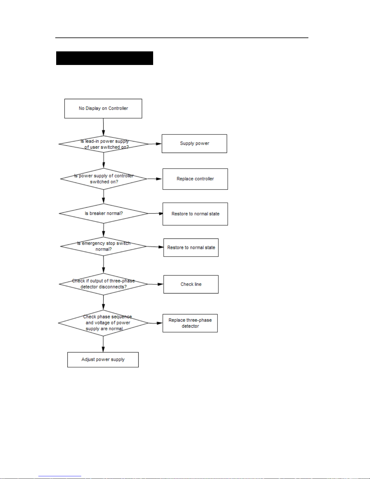
Flooded Type Water Cooled Screw Chiller Technical M
anual
63
3.2 Analysis and Solution of Failure without Failure Code
No Display on Controller
Namely that controller doesn’t display anything.
YES
YES
YES
YES
YES
YES
NO
NO
NO
NO
NO
NO
Page 67
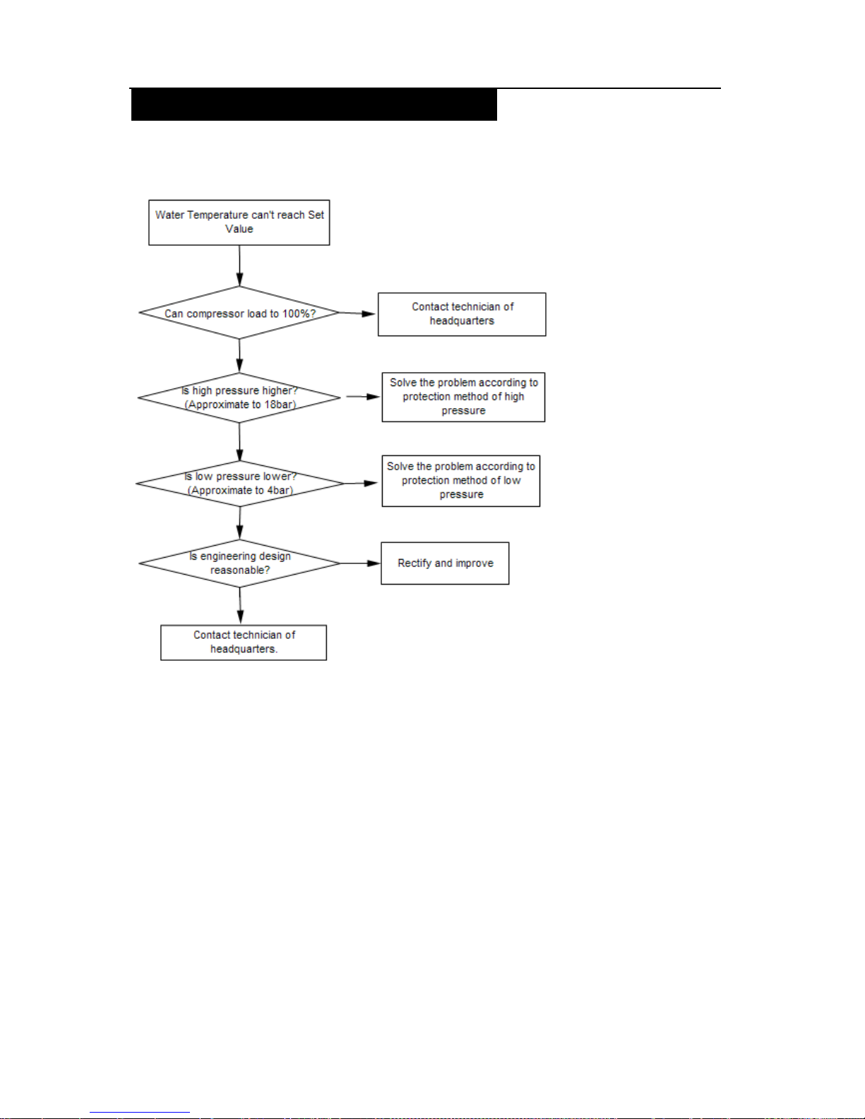
Flooded Type Water Cooled Screw Chiller Technical M
anual
64
Water Temperature can’t reach Set Point
Water temperature can’t reach set point despite of longtime startup.
YES
YES
YES
YES
NO
NO
NO
NO
Page 68
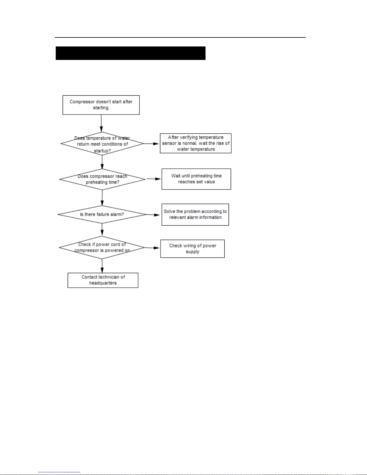
Flooded Type Water Cooled Screw Chiller Technical M
anual
65
No Startup of Compressor After Starting
Compressor doesn’t start after pressing start key and normal time delay.
YES
YES
YES
YES
NO
NO
NO
NO
Page 69
Flooded Type Water Cooled Screw Chiller Technical M
anual
66
4. Failure Detection of Electrical Parts
No.
Name of
Parts
Detection Methods
1 Compressor
1. After detecting with OHM range of multimeter, there is correct resistance
value (three-phase resistance value of compressor should be
approximately the same) among windings. Winding resistance to shell
resistance should be infinite.
2 Contactor
1、 Movable contact should act flexibly without blocking after contactor is
manually pressed.
2、 Contact of contactor shouldn’t be burnt out.
3、 Coil should have resistance value below K-class, but shouldn’t be “0”
or infinite.
3 Sensor
1. Measure resistance value with multimeter and find out temperature by
referring to resistance table. The temperature should be the same as
the temperature at location of sensor.
2. Resistance value shouldn’t be “0” or infinite.
Page 70
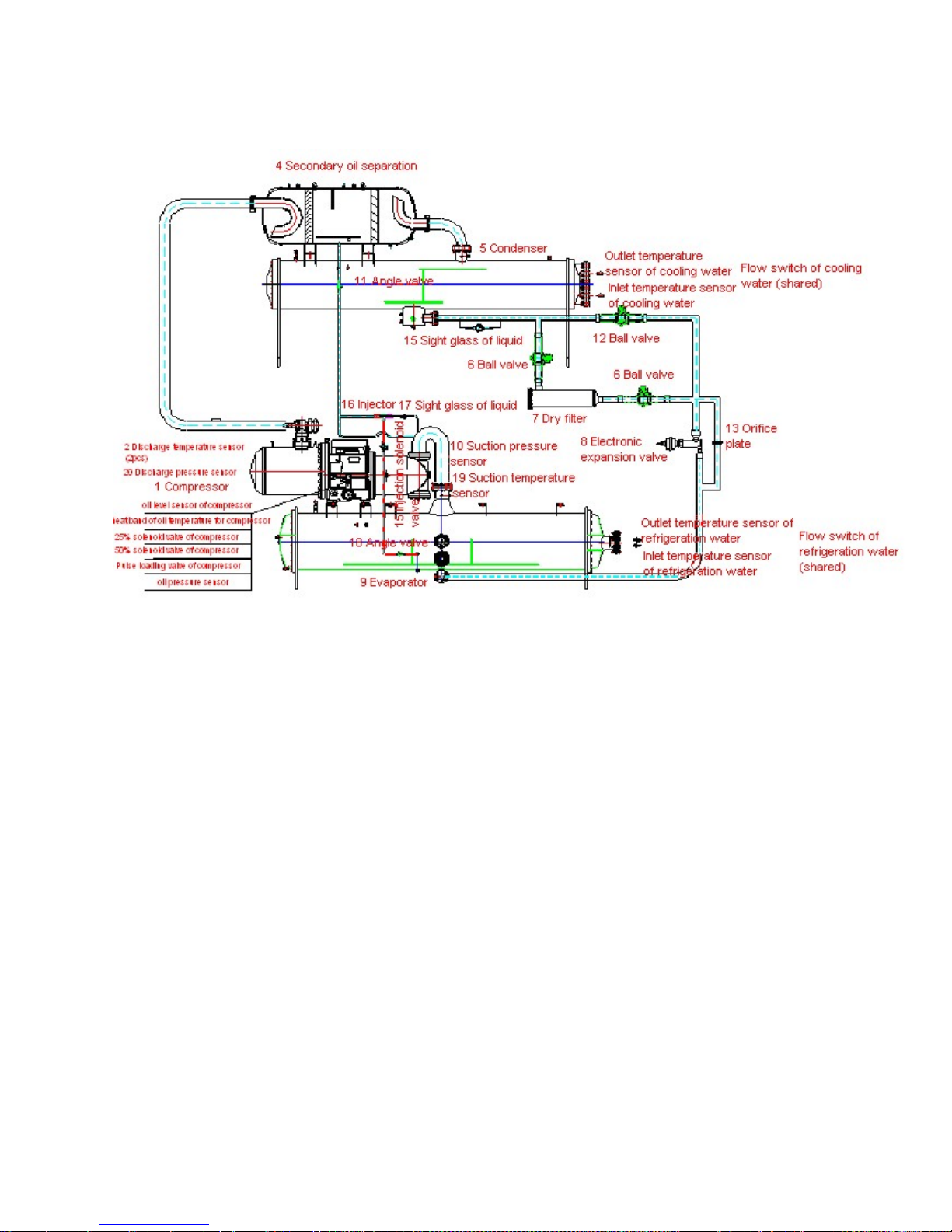
Flooded Type Water Cooled Screw Chiller Technical Manual
67
5. Schematic Diagram of System and Electrical Schematic Diagram
Schematic Diagram of Screw Unit System with Flooded-type Independent System:
Page 71
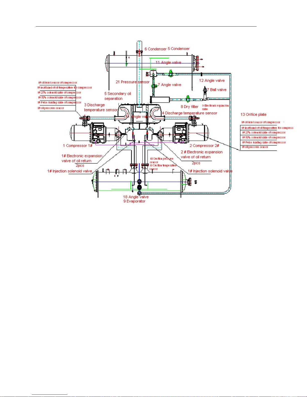
Flooded Type Water Cooled Screw Chiller Technical Manual
68
Schematic Diagram of Flooded-type Double-head Screw Unit System:
Cooling cycle: compressor sucks low-temperature low-pressure refrigerant from evaporator into
compressor and discharges them into oil/gas separator after compressing them into
high-temperature high-pressure gas; in oil separator, oil carried by high-pressure gas is
filtered, remained in oil separator and then it returns to compressor through oil return pipeline;
the filtered high-pressure gas comes into condenser; in condenser, high-temperature
high-pressure refrigerant gas exchanges heat with cooling water in pipeline, condenses into
high-temperature high-pressure refrigerant liquid after transferring heat to cooling water, and
comes into evaporator after being throttled, cooled and depressurized by orifice plate or
electronic expansion valve; gas-liquid two-phase refrigerant coming into evaporator totally
evaporates in evaporator to cool down refrigeration water; vapor from evaporator is sucked
and compressed by compressor again. It cycles continuously in this way. Cooled refrigeration
water is sent by pipeline to end equipment, creating comfortable living and working
environment.
Page 72
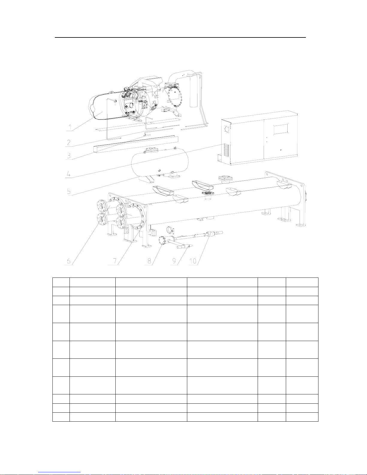
Flooded Type Water Cooled Screw Chiller Technical M
anual
69
6. Exploded Chart and Bill of Material
Exploded Chart of Screw Unit with Flooded-type Independent System:
N0. Material code Part Name-Chinese Part Name-English Quantity Remark
1
压缩机
Compressor 1
2
毛细管
Capillary pipe 1
3
回油引射泵
Injection pump of oil
return
1
4
电控箱组件
Component of electric
control cabinet
1
5
油分离器(卧式)
Oil separators
(horizontal-type)
1
6
壳管式蒸发器
Shell and tube
evaporator
1
7
壳管式冷凝器
Shell and tube
condenser
1
8
干燥过滤筒
Dry filter cartridge 1
9
角阀
Angle valve 1
10
球阀
Two way ball valve 1
Exploded Chart of Flooded-type Parallel Screw Unit:
Page 73
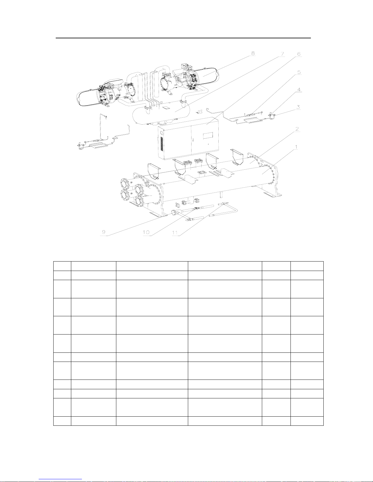
Flooded Type Water Cooled Screw Chiller Technical M
anual
70
N0. Material code Part Name-Chinese Part Name-English Quantity Remark
1
壳管式冷凝器
Shell and tube condenser 1
2
壳管式蒸发器
Shell and tube
evaporator
1
3
电子膨胀阀阀体
Body of electronic
expansion valve
6
4
电子膨胀阀线圈
Coil of electronic
expansion valves
6
5
回油引射泵
Injection pump of oil
return
2
6
电控箱组件
Electric control 1
7
油分离器(卧式)
Oil separators
(horizontal-type)
1
8
压缩机
Compressor 2
9
干燥过滤筒
Dry filter cartridge 1
10
节流电子膨胀阀 ETS
Electronic expansion
valves ETS
1
11
角阀
Angle valve 2
Page 74
Flooded Type Water Cooled Screw Chiller Technical M
anual
71
•Consultation Service – AUKS headquarters and all distribution centers
have established service hotline to accept consultation from users.
• Training and Technical Support –users are welcomed to contact AUKS for any
problem related to technology of A/C system. AUKS will provide
training and technical support on operation and management
of A/C system for users free of charge.
•After-sales Service System – If A/C system breaks down, users can dial service
hotline of headquarters or number of local authorized
maintenance station. Maintenance personnel will quickly go
to the spot and deal with the problem within 24 hours after
receiving service requirement.
•Return visit and Follow-up Service – AUKS provides effective return visit and follow-up
services for the sold products and customer service status.
• Content published in this material may subject to change due to product update without notice.
• This material has proofread many times to ensure accuracy. However, it is used for reference only.
Everything should subject to physical object, nameplate of product and instruction manual.
Page 75

Flooded Type Water Cooled Screw Chiller Technical M
anual
72
_______________________________________________________________________
ADD:NO. 1166 North MingGuang Road (AUKS Technology park), JiangShan
Town, Zhejiang, P.R.China
TEL:86-574-88220539
FAX:86-574-88220597
CODE:315191
URL:http://www.cnAUKS.com
VERSION: Flooded Type Water Cooled Screw Chiller-2010-01
 Loading...