

auer IC3P, IC3S Operating Manual
Weatherproof Intercom S tation
Operating manual
IC3P / IC3S 1.0_E
IC3P / IC3S

2 / 16
Operating Manual - IC3P /IC3S
Notes
Please read the operating manual carefully before installing the device.
Texts and illustrations have been compiled and software created with the utmost care,
however errors cannot be completely ruled out. This documentation is therefore supplied
under exclusion of any liability or warranty of suitability for specific purposes. J.Auer
reserves the right to improve or modify this documentation without prior notice.
Before opening or dismounting the device it has to be separated from
all voltage supply
.
General Description
The IC3P / IC3S is a
weatherproof Intercom Station which can be operated in the
analogue, public telephone network or can be connected to analogue terminals of branch
exchanges.
The IC3P / IC3S is available in different designs:
With casing it is made for wall mounting or it can be fixed on pylons and joists.
Without casing it is meant as built-in unit.
This manual describes below the construction with casing. The connection of the built-in
unit is made correspondingly, but without considering the cable entries.
The IC3P / IC3S Station comprises
- a loudspeaker and
- a microphone for voice communication
- a hookswitch key as operating element
- three key buttons for direct dialing
- and a LED (part of the hookswitch key)as loop current indicating element.
Utilization and programming is identical in all devices.
Features
- Pulse / tone dialing
- Automativ cleardown
capability
- Automatic answering capability or answering after a programmable number of
rings
-
Choice of up to three programmable direct dialing numbers
-
Remote programming of
telephone number
ringer volume
ringer melody
loudspeaker volume
automatic call acceptance
dialing type
3 / 16
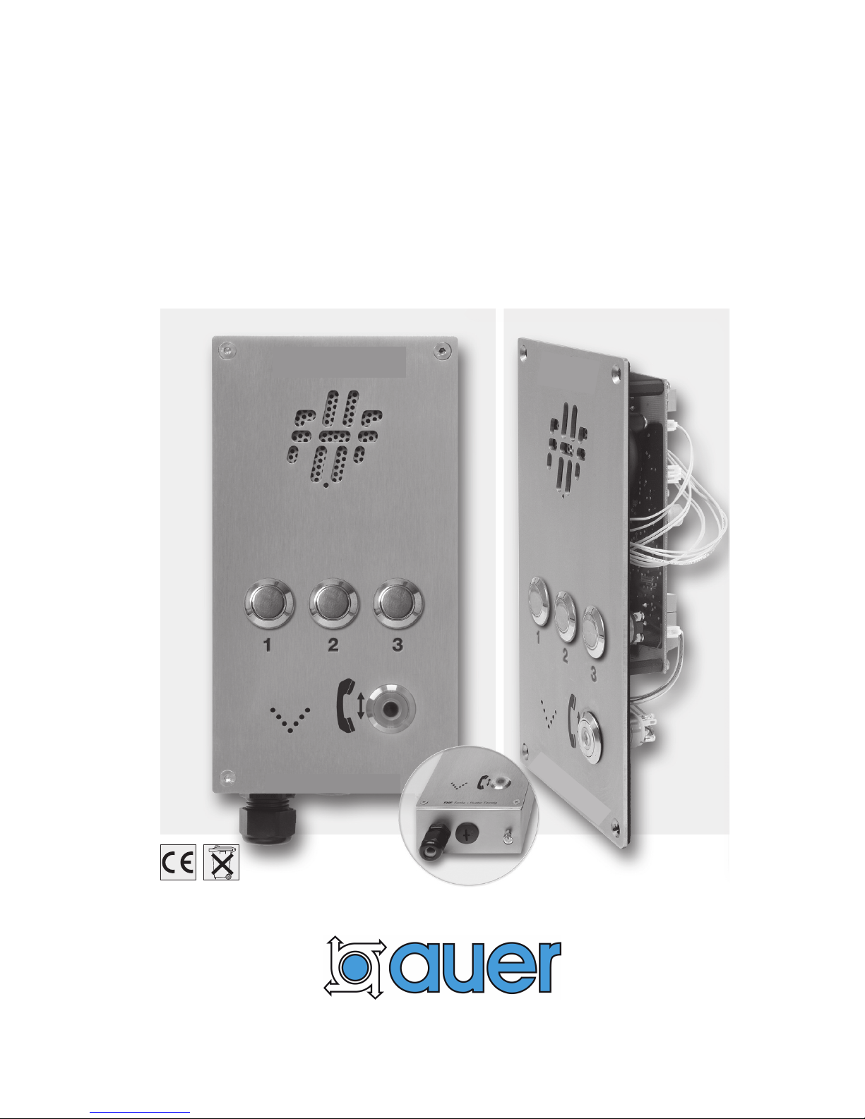
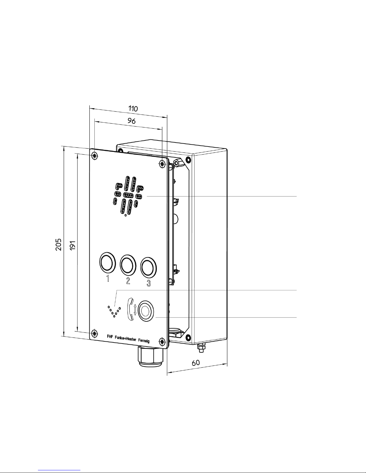
IC3S
with casing
Loudspeaker
Microphone
Loop Current
Indicator
Hook switch
key
4 / 16
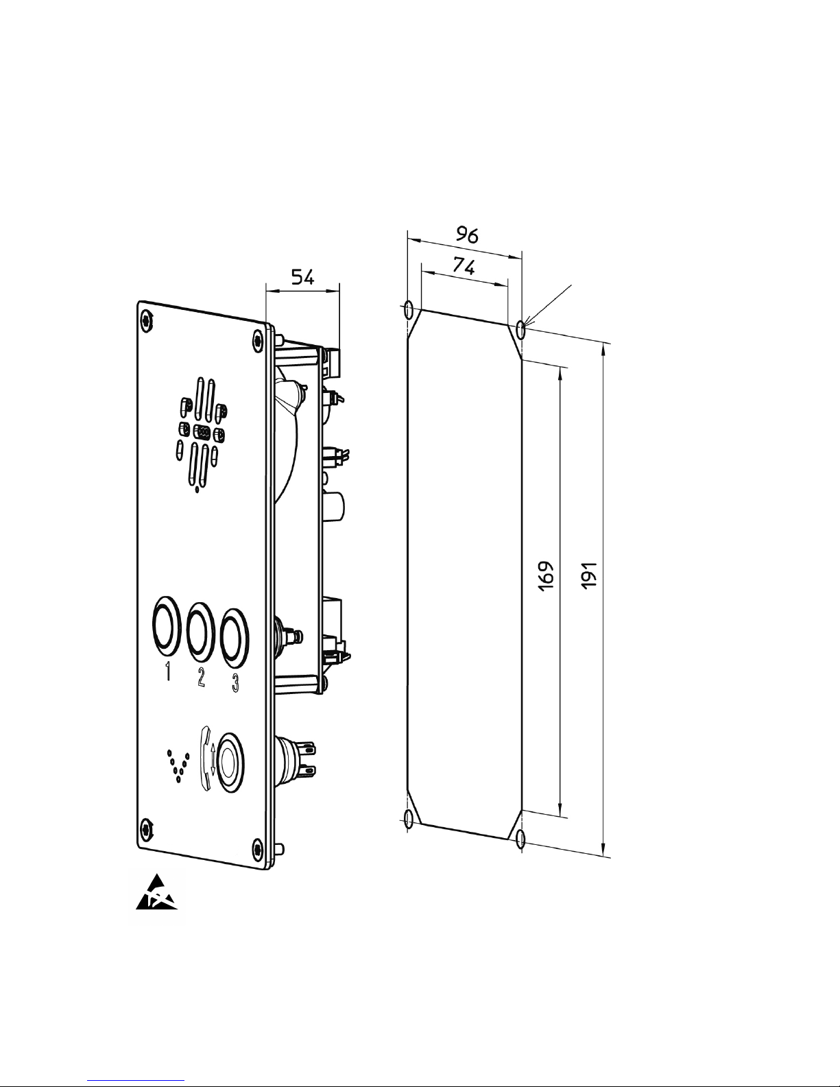
IC3P
built-in unit
assembly cut-out
thread M4 or
Ø 4.3 mm
5 / 16
Connection
Opening the IC3P / IC3S
To gain access to the circuit board or the tamper alarm switch, unfasten the four
screws in the front panel.
Attention: Before opening or dismounting the device it has to be separated from
all voltage supply.
Concluding notes
CE (cable entry) M20 x 1.5
Protection rating CE IP66
Connection cable Ø 5 to 9 mm
Wire and connector diameter 0.14 to 2.5 mm
2
Only appropriate tools may be used for the assembly of the CE. The cable connection
is suitable for firmly secured conduits only. When locking the equipment, ensure tight
fit and cleanliness of all sealing. To retain the protection rating IP 66, cover screws
must be screwed in either side, diagonally with 1.4 Nm each.
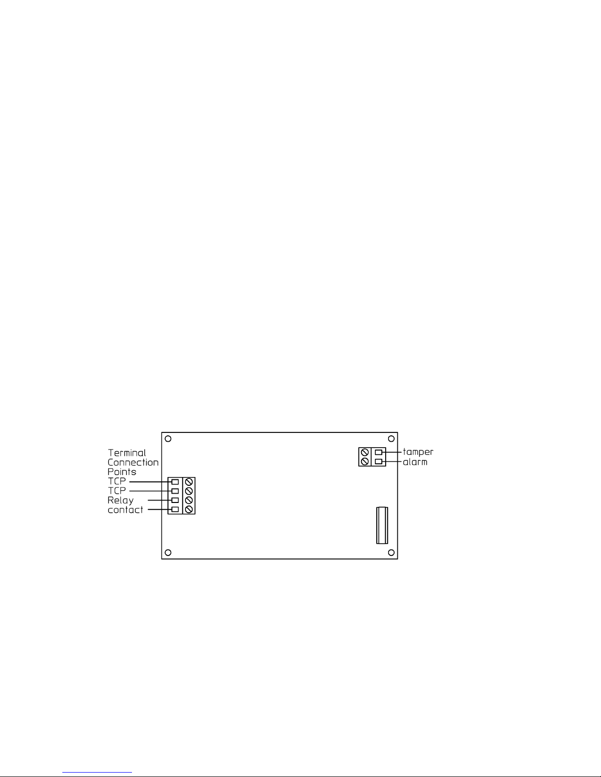
Connection of the tamper alarm switch
Pull the control line through the cable gland of the box and connect the two wires to
the insulated screw joints of the tamper alarm switch. The voltage and the maximum
power in the tamper alarm circuit shall not exceed 60 V
DC
or 30 V
AC
respectively
30 W.
Connection of the telephone line
Pull the telephone line through the cable gland of the box and connect it to the
Terminal Connection Points TCP.
 Loading...