

Page 1
Operating instructions
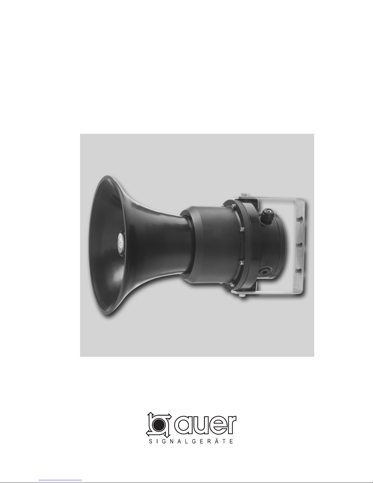
EEx Sounder
Typ dHE
dHE 2.0 1
Page 2

2
Note
Please read this manual carefully before installing the sounder.
Application
The EEx Sounder dHE is a signalling device that generates various signalling tones and
signalling tone sequences and emits them at a high sound pressure level. The user may
choose between 31 preset signalling tone groups and one programmable one. Every
signalling tone group contains 4 different signalling tones. Wire the control inputs with
floating contacts or jumpers in order to chose any one of these 4 signalling tones. The
sounder has 8 volume levels. All outer fastening parts are made of non-corrosive materials.
The stable, all-plastic housing conforms to protection degree IP 66, which means the
sounder can be installed both indoors and outdoors. Explosion category II 2 G EEx dem
IIC T6 allows the sounder to be operated in hazardous areas of zones 1 and 2.
Setting the volume and the signalling tone groups prior to mounting the sounder
The sounder ships with the following setting:
Sound pressure: maximum
Signalling tone group: Group0:
continuous tone 1000 Hz; sweeping tone 1200 Hz / 500 Hz;
intermittent tone 1000 Hz
Selected signalling tone: continuous tone 1000 Hz
If you want other signalling tones and volume levels, please follow the instructions below.
To set the sound pressure level and the signalling tone groups, open the sounder housing.
To do this you have to place the sounder on a level surface, the loudspeaker opening facing
upwards. Loosen the 8 housing screws and lift the upper part of the housing slightly. Detach
the connecting cable running from the loudspeaker to the circuit board at the circuit board
and put the loudspeaker part aside. In the bottom part of the housing, on the circuit board,
you will find the controls and an LED that are required to set the signalling tone groups.
Page 3

3
Vol./Prog.
Select
0..F
Group/Tone
Select
LS: 0.. F
US: 10..1F
Enter
LS:
US:
0.. F
10..1F
Lower/Upper Select
S1 S2
S3
X1
0F
E
D
C
B
A
9
8
7
6
5
4
3
2
1
0F
E
D
C
B
A
9
8
7
6
5
4
3
2
1
H1
rotary switch S2 = 0
rotary switch S1 = 7
push button S3
LED H1
internal plug
connector
plug connector loudspeaker
j
umper field X1 = LS
Controls:
Rotary switch S1: Vol./Prog.
Select
0..F
Settings:
0-7 Sound pressure level setting for normal operation. The 0 setting results in normal
operation with the lowest possible volume, whereas the 7 setting results in normal
operation with the highest possible volume.
8-B Programming the signalling tone group GroupF. The device is forced to go mute
and LED H1 is switched on.
C-F Reserved, do not set! The device is forced to go mute.
Note:
Setting the reserved positions C-F may alter the programming of the signalling tone
group GroupF.
Rotary switch S2: Group/Tone
Select
LS: 0..F
US: 10..1F
Settings:
0-F Selecting the signalling group Group0.. GroupF, when the jumper for LS has been
set,
or
0-F Selecting the signalling group Group10.. Group1F, when the jumper for US has
been set,
Page 4

4
Jumper field X1: Lower/Upper Select
LS: 0..F
US: 10..1F
Settings:
Jumper LS: Signalling tone group Group0...GroupF is selected using rotary switch
S2.
Jumper US: Signalling tone group Group10...Group1F is selected using rotary
switch S2.
Notes:
If a jumper is lacking the setting LS is active.
Set the jumpers in the marked positions LS or US of the jumper field only. Setting the
jumpers in any other position might reduce the functionality of the device.
Push button S3 Enter
Key for programming the signalling tone group GroupF.
LED H1
Programming assistance LED
Procedure for setting the sound pressure level
The programming procedure described below must be performed outside of
hazardous areas only, because the opened device has to be supplied with voltage
during the procedure.
Turn the rotary switch S1 (Vol./Prog. Select 0..F) to a position between 0 and 7. Position 7
represents the maximum sound pressure level. For each of the positions 6 through 0 the
sound pressure level is reduced by 3 dB(A).
Procedure for setting a signalling tone group
The active signalling tone group determines the 4 signalling tones that may be selected
from the control inputs during operation.
Setting the active signalling tone group
a.) From the table „Signalling tone groups“, select the group to which the 4 signalling tones
belong that you want to select by connecting the control inputs during operation.
b.) If the selected signalling tone group belongs to one of the groups Group0 to GroupF,
place the jumper in jumper field X1 in position LS. Otherwise, place the jumper in
position US. Turn the rotary switch S2 (Group/Tone Select LS:0..F US: 10..1F) to the
position corresponding to the last character of the line name of the selected signalling
tone group. For instance to position A for the selected signalling tone group GroupA or
to position 5 for the selected signalling tone group Group15.
For the signalling tone group GroupF, the composition of the 4 signalling tones is freely
programmable. Any one of the signalling tones Tone0 to Tone1F from the table “Signalling
tone description” may be freely assigned to the settings Stage 0, Stage 1, Stage 2 and
Stage 3. This programming procedure is described in greater detail below.
Page 5

5
Signalling tone group GroupF programming procedure
Any one of the signalling tones from the table “Signalling tone description” may be freely
assigned to the settings Stage 0, Stage 1, Stage 2 and Stage 3 of the signalling tone group
GroupF, in order to compose exactly the 4 signalling tones in signalling tone group GroupF
that are required for a certain application.
Programming the signalling tone group GroupF
a.) First, turn the rotary swi tch S1 (Vol./Prog. Select 0..F) to one of the positions 8, 9, A or
B, in order to force the device into the “mute” setting when the mains supply is switched
on.
b.) Turn on the mains supply of the device. The device goes mute and LED H1 is switched
on.
c.) In order to change a particular signalling tone, use the rotary switch S1
(Vol./Prog. Select 0..F) to select the corresponding setting among the Stage 0, Stage 1,
Stage 2 or Stage 3 settings of signalling tone group GroupF. Do this by turning the
rotary switch S1 to position 8 (Stage 0), 9 (Stage 1), A (Stage 2) or B (Stage 3).
d.) Select the desired new signalling tone from the table “Signalling tone description”.
e.) If the selected signalling tone belongs to the tone interval Tone0 to ToneF, place the
jumper in jumper field X1 in position LS. Otherwise, place the jumper in position US.
Turn the rotary switch S2 (Group/Tone Select LS:0..F US: 10..1F) to the position
corresponding to the last character of the line name of the selected signalling tone. For
instance to position A for the selected signalling tone ToneA
or to position 5 for the
selected signalling tone Tone15.
f.) Press push button S3 (Enter) to trigger the programming procedure. LED H1 will be
turned off during programming, and then on again after the programming is completed.
Repeat steps c.) to f.) for all the settings of those tones of signalling tone group GroupF
that you want to change.
g.) Turn off the mains supply of the device.
h.) Turn rotary switch S1 (Vol./Prog. Select 0..F) back to the preferred volume setting
between position 0 and 7, place the jumper in jumper field X1 in position LS, and turn
rotary switch S2 (Group/Tone Select LS:0..F US: 10..1F) to position F.
Pick up the loudspeaker part of the housing again, connect the loudspeaker cable with the
circuit board in the lower part and place the loudspeaker part on top of the lower part.
Connect the housing parts with each other using the 8 housing screws.
(Torque 3 Nm ± 0.3 Nm)
Page 6

6
Setting the volume and the signalling tone groups following sounder mounting
If the signalling tone and sound pressure level settings must be changed after the device
has been mounted, the sounder must be dead (no-voltage). Wait more than 15 minutes
before opening the device.
Loosen the 8 housing screws and lift the upper part of the housing slightly. Detach the
connecting cable running from the loudspeaker to the circuit board at the circuit board and
put the loudspeaker part aside. Perform the setting as described above.
Warning:
The programming of signalling tone group GroupF must be performed outside of
hazardous areas only, because the opened device has to be supplied with voltage
during the procedure.
Page 7
7
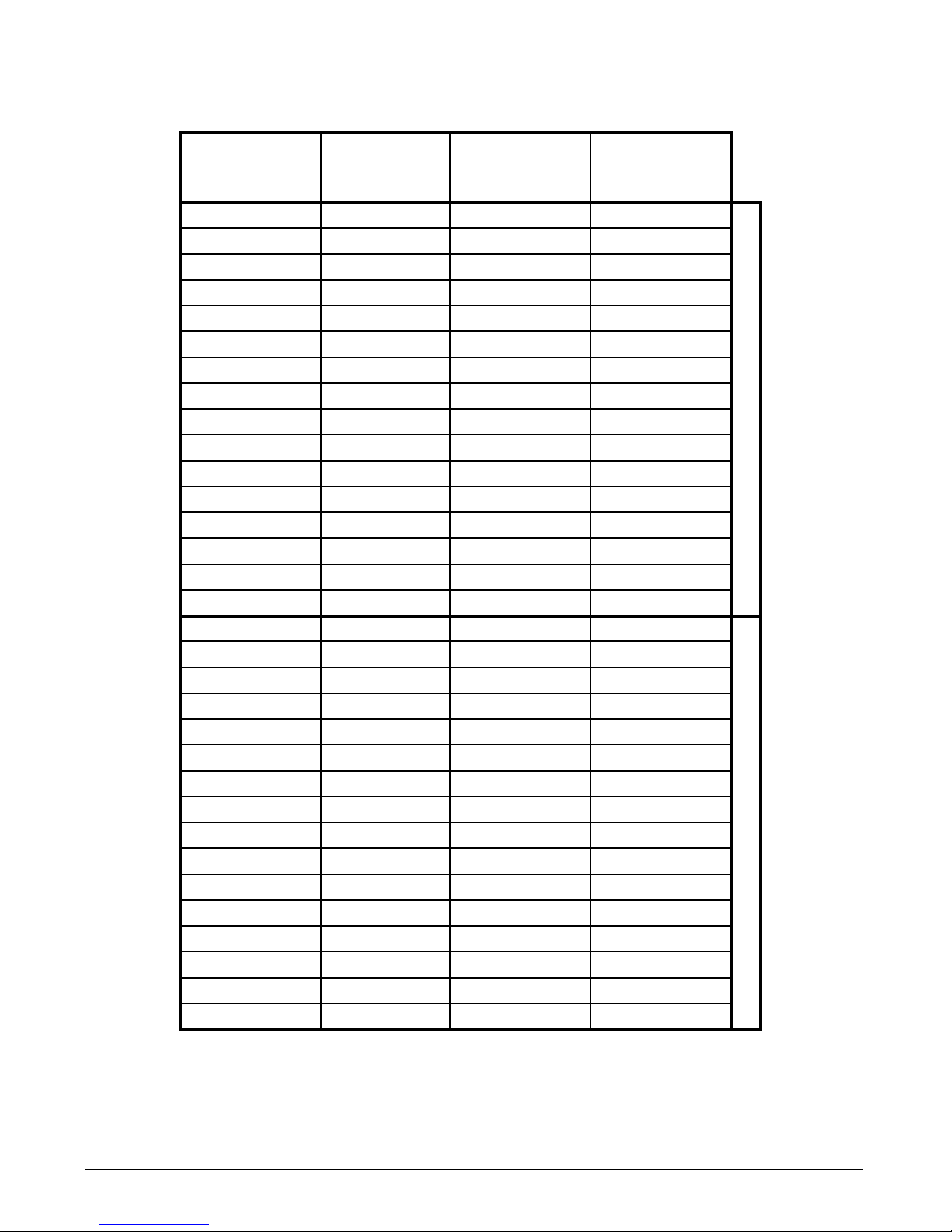
Table: Signalling tone groups
Stage 0..Stage 3 represent the signalling tones selected via the connections of the control
inputs.
Stage 0
3 4 5
Stage 1
3-----4 5
Stage 2
3 4-----5
Stage 3
3-----4-----5
1)
Group0 Mute Tone0 Tone1E Tone9
Group1 Mute Tone1 ToneB Tone13
Group2 Mute Tone2 Tone1 Tone13
Group3 Mute Tone3 Tone4 Tone13
Group4 Mute Tone4 Tone5 Tone13
Group5 Mute Tone5 Tone8 Tone13
Group6 Mute Tone6 Tone1 Tone13
Group7 Mute Tone7 Tone12 Tone1
Group8 Mute Tone8 Tone5 Tone13
Group9 Mute Tone9 Tone1E Tone0
GroupA Mute ToneA Tone3 Tone13
GroupB Mute ToneB Tone1 Tone1A
GroupC Mute ToneC Tone1 Tone13
GroupD Mute ToneD ToneE Tone13
GroupE Mute ToneE Tone1 Tone13
GroupF Mute
2) S1 = 8
ToneF
2) S1 = 9
Tone1
2) S1 = A
Tone13
2) S1 = B
Jumper in position LS of
j
umper field X1
Group10 Mute Tone10 Tone12 Tone13
Group11 Mute Tone11 Tone3 Tone13
Group12 Mute Tone12 Tone1 Tone13
Group13 Mute Tone13 Tone2 Tone1A
Group14 Mute Tone14 Tone1 Tone13
Group15 Mute Tone15 Tone1 Tone13
Group16 Mute Tone16 Tone4 Tone13
Group17 Mute Tone17 Tone1C Tone13
Group18 Mute Tone18 Tone1C Tone13
Group19 Mute Tone19 Tone1 Tone0
Group1A Mute Tone1A Tone19 Tone13
Group1B Mute Tone1B Tone1 Tone13
Group1C Mute Tone1C Tone5 Tone13
Group1D Mute Tone1D Tone1F Tone13
Group1E Mute Tone1E Tone9 Tone0
Group1F Mute Tone1F Tone19 Tone0
Jumper in position US of
j
umper field X1
1)
Corresponding connections for input terminals 3, 4 and 5.
2)
The signalling tone group GroupF ships in the following state. The assignment of the
signalling tones may be changed by programming. The entry S1 = x identifies the required
position of the rotary switch S1 (see „ Signalling tone group GroupF programming procedure “).
Page 8
8
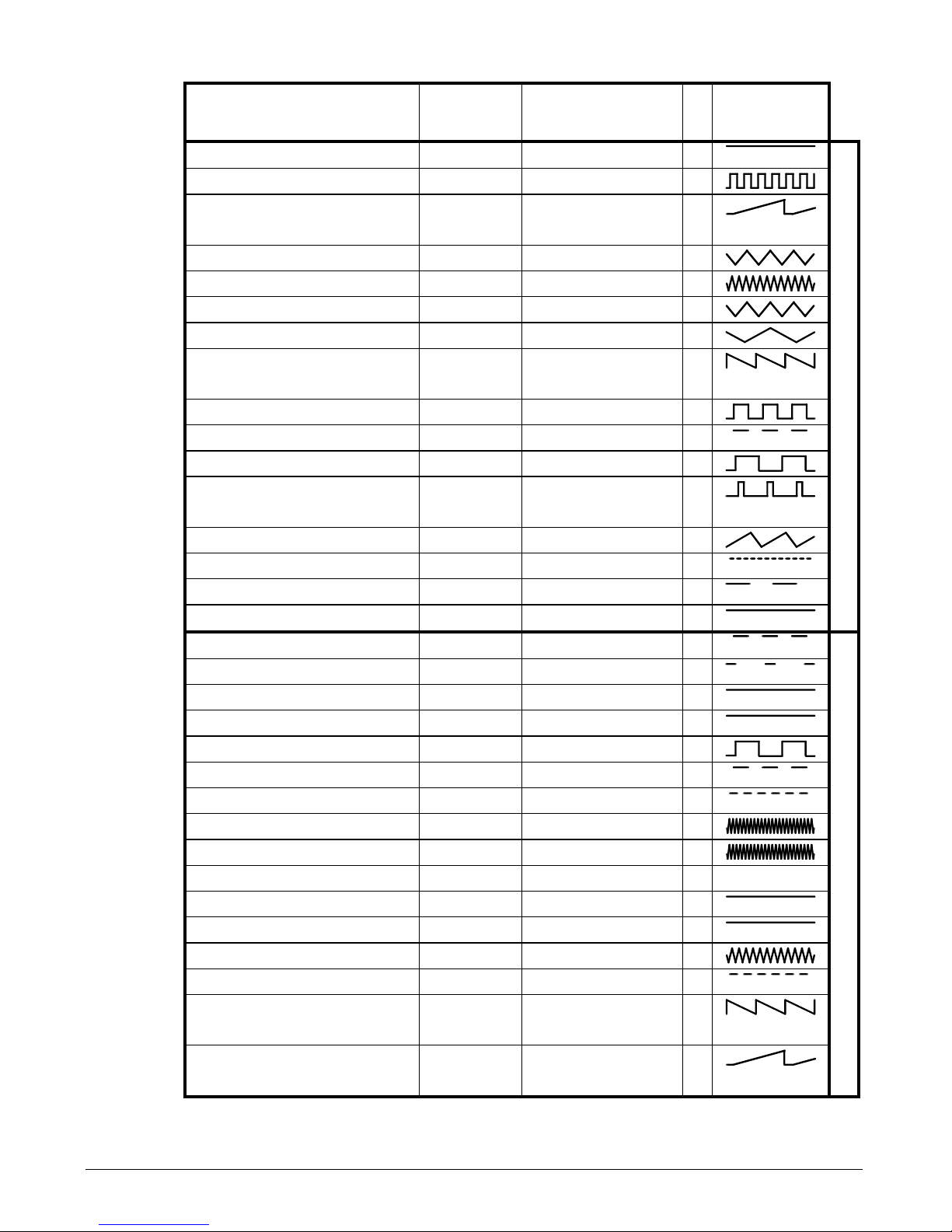
Table: Signalling tone description
Parameter Type Standard
Sy
nc
Timing
diagram
Tone0 1000Hz Continuous PFEER Toxic Gas
Tone1 800/1000Hz@ 0.25s Alternating
Tone2 500/1200Hz@ 0.3Hz 0.5s Slow
Whoop
a
aa
a
Tone3 800/1000Hz@ 1Hz Sweeping a
aa
a
Tone4 2400/2900@ 7Hz Sweeping
Tone5 2400/2900@ 1Hz Sweeping a
aa
a
Tone6 500/1200Hz@ 0.3Hz Sweeping a
aa
a
Tone7 1200/500Hz@ 1Hz Sweeping DIN /
P
FEER P.T.A.P.
aaaa
Tone8 2400/2900@ 2Hz Alternating a
aa
a
Tone9 1000Hz@ 1Hz Intermittent a
aa
a
ToneA 800/1000Hz@ 0.875Hz Alternating a
aa
a
ToneB 544Hz(100ms)/440Hz(400
ms)
Alternating NF S-32-001 a
aa
a
ToneC 1400Hz(1s)/1600Hz(0.5s) Sweeping NFC48-265 a
aa
a
ToneD 660Hz@ 3.33Hz Intermittent
ToneE 660Hz/(1.8s),1.8s off Intermittent a
aa
a
ToneF 660Hz Continuous
Jumper in position LS of jumper field X1
Tone10 2400Hz@ 1Hz Intermittent a
aa
a
Tone11 800Hz(0.25s), 1s off Intermittent a
aa
a
Tone12 800Hz Continuous
Tone13 2400Hz Continuous
Tone14 554/440Hz@ 1Hz Alternating a
aa
a
Tone15 544Hz@ 0.875Hz Intermittent a
aa
a
Tone16 800Hz@ 2Hz Intermittent a
aa
a
Tone17 800/1000Hz@ 50Hz Sweeping
Tone18 2400/2900Hz@ 50Hz Sweeping
Tone19 Mute
Tone1A 554Hz Continuous
Tone1B 440Hz Continuous
Tone1C 800/1000Hz@ 7Hz Sweeping
Tone1D 420Hz 1.6Hz Intermittent Australian Alert a
aa
a
Tone1E 1200/500Hz@ 1Hz Sweeping DIN / PFEER
P.T.A.P.
aaaa
Tone1F 500/1200Hz@ 3.75s
0.25s
Slow
Whoop
Australian Evac. a
aa
a
Jumper in position US of jumper field X1
Page 9
9
Possible applications
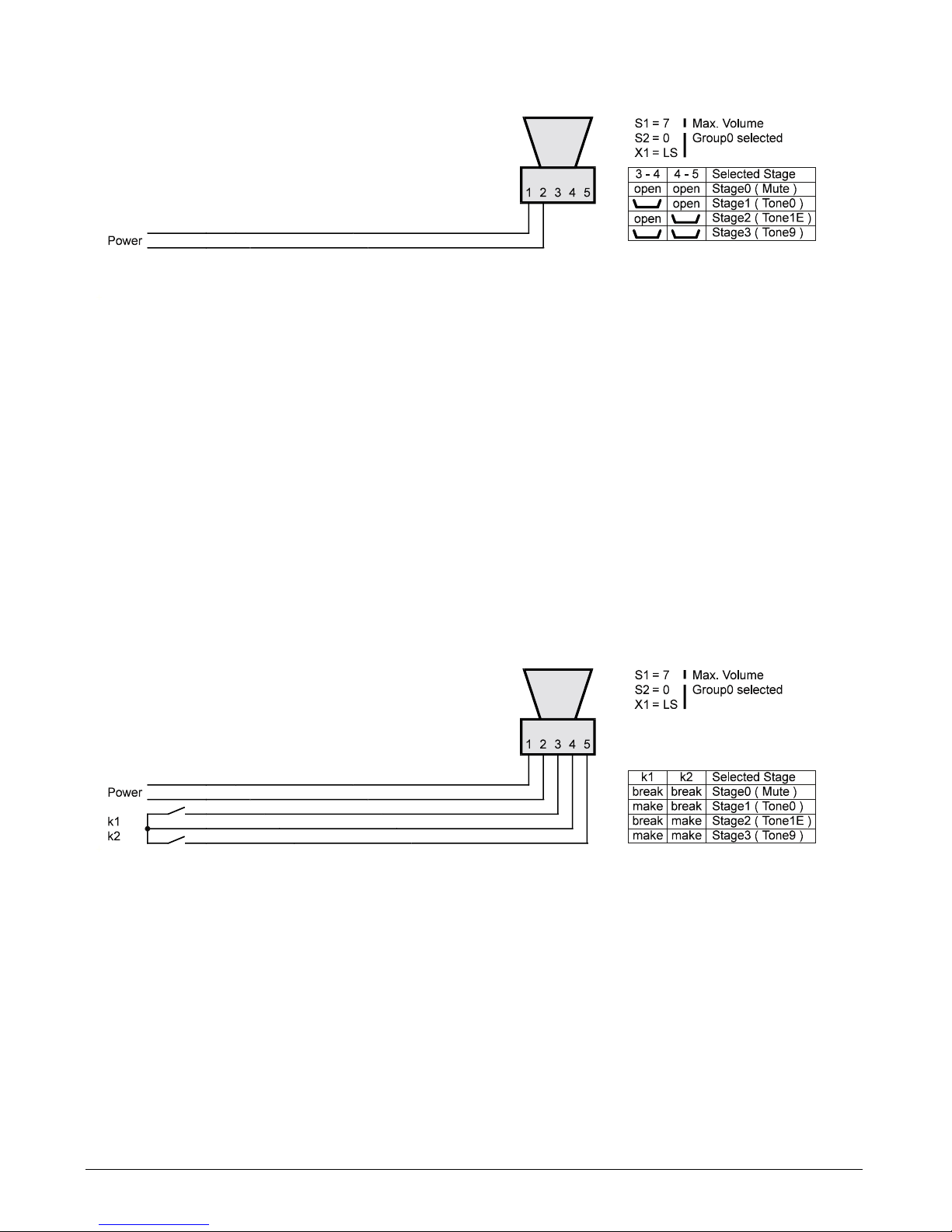
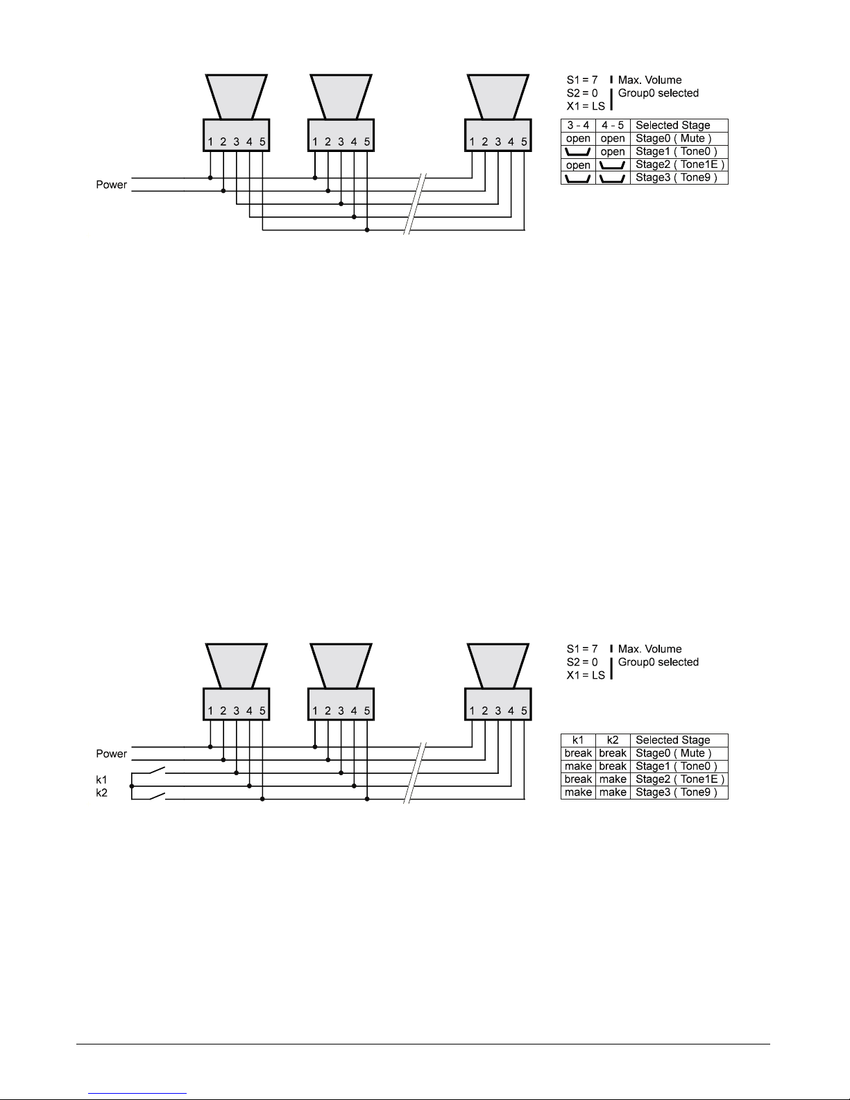
Single sounder with a fixed signalling tone:
You have selected a signalling tone group according to the procedure described earlier in
this manual. To select a fixed signalling tone (Stage 0, Stage 1, Stage 2 or Stage 3) from
the signalling tone group, the control inputs must be connected accordingly. The control
inputs are the terminals 3, 4 and 5, located in the sounder’s electrical enclosure. Place the
sounder with the horn opening resting on a level surface, loosen the 6 screws of the
electrical enclosure lid and remove the lid.
Perform the setting of a fixed signalling tone as follows:
Stage 0 No connections
Stage 1 Connect terminal 3 and terminal 4 using a jumper
Stage 2 Connect terminal 4 and terminal 5 using a jumper
Stage 3 Connect terminals 3, 4 and 5 using a jumper.
Single sounder with variable signalling tone:
If there is a requirement for the ability to select the individual signalling tones of a signalling
tone group (Stage 0, Stage 1, Stage 2 or Stage 3) during operation, terminals 3, 4 and 5
must be connected accordingly to the floating contacts of a control device. This may be
prepared at this stage, or after the sounder has been mounted.
Select a signalling tone via floating contacts k1 and k2 as follows:
Stage 0 Both contacts open
Stage 1 Contact k1 closed, contact k2 open
Stage 2 Contact k1 open, contact k2 closed
Stage 3 Both contacts closed
Page 10
10
Multi-sounder with a fixed signalling tone:
If several sounders are being operated simultaneously with the same signalling tone, it
may be a good idea to synchronise the signalling tones, i.e. to make sure the signalling
tones of all the sounders sound for an equally long period of time. This is only possible with
the signalling tones for which “Sync” has been ticked off in the table “Signalling tone
description”. To enable synchronisation, the terminals 3 of all the sounders, the terminals 4
of all the sounders and the terminals 5 of all the sounders must be interconnected.
To select a fixed signalling tone (Stage 0, Stage 1, Stage 2 or Stage 3) from the set
signalling tone group, the control inputs of one of the sounders must be connected
accordingly. This may be prepared at this stage, or after the sounder has been mounted.
Perform the setting of a fixed signalling tone as follows:
Stage 0 No connections
Stage 1 Connect terminal 3 and terminal 4 using a jumper
Stage 2 Connect terminal 4 and terminal 5 using a jumper
Stage 3 Not a useful setting in this application, as synchronisation is not possible
when terminals 3, 4 and 5 are interconnected.
Multi-sounder with variable signalling tone:
As „Multi-sounder with a fixed signalling tone“, except that the signalling tone may be
chosen via floating contacts of a control device.
Select a signalling tone via floating contacts k1 and k2 as follows:
Stage 0 Both contacts open
Stage 1 Contact k1 closed, contact k2 open
Stage 2 Contact k1 open, contact k2 closed
Stage 3 Both contacts closed. Please note that for this selection a
synchronisation of the signalling tones is not possible.
Page 11

11
Mounting
The sounder is suited for wall and ceiling mounting. For mounting dimensions, see the
dimension illustration (on page 12). The wall bracket included in the box is fastened with 2
screws (∅ 6 or 8 mm). To connect, loosen the 6 lid screws and remove the lid. The
fasteners and the mounting surface must be able to safely carry the weight of the sounder.
Installation
Prior to leading the connecting sounder cables through the cable gland, 100 – 130 mm of
the isolation must be removed. Before connecting the single connectors to the terminals,
remove 8 to 10 mm of isolation from the connectors.
Terminal Version 85 - 265VAC Version 21.6 - 75VDC
1, 1 N L+ / L2, 2 L1 L- / L+
3
4
5
After connecting the loudspeaker, place the single conductors of the connecting cables
flatly across the connecting terminals, in the direction of the cable gland.
Warning! To avoid the connectors getting pinched, do not place them over the sealing
edge.
Use sufficiently long cables to facilitate positioning of the sounders at a later stage.
Close the lid
Prior to closing the lid, the sealing surfaces and the sealing must be checked for damage
and dirt, and cleaned if necessary. Damaged seals must be replaced by original seals from
the manufacturer.
Put the lid on. Make sure the lid sits straight, and that the „lid fastener“ has not been placed
across the threaded lid bolt or across the sealing edge. Then turn the lid screw as far as it
goes, and tighten lightly.
Positioning the sounder
Swing the sounder in the desired position and tighten both side screws on the wall bracket.
Operating position
In order to avoid a reduction of the volume due to dust, rainwater or other foreign matter,
the horn should be mounted horizontally or facing downwards.
Care and maintenance
The sounder is maintenance-free. In very dusty or dirty surroundings, the sounder should
nevertheless be cleaned with a damp cloth from time to time. Never use sharp objects for
cleaning.
Special operating conditions
In order to maintain the given listening quality, the sounder must not be mounted in close
vicinity of sources of magnetic fields with technically relevant frequencies.
Page 12

12
Disposal
The device may be recycled as electronic waste. When the device is disassembled,
plastics, metals and electronics are to be disposed of separately. In every single case the
national requirements and regulations for waste disposal must be observed.
User Information
This is a flameproof device designed for operation in explosive atmospheres. As a group
II, category 2 device it is designed for use in Zone 1 and 2.
Please note the following warnings and security information:
1. The installation and adjustment of the device must be carried out by qualified personnel in
accordance with the prescribed installation regulations taking the specified explosion category
into account. Repairs only may be carried out by the manufacturer or by a person appointed by
the manufacturer followed by a renewed product conformity inspection.
2. This device corresponds to insulation class II according to EN 60335-1
3. If the device is damaged, it may not be operated.
4. While operating the device in business or industry facilities, the legally or otherwise require d
precautions against accidents resulting from the use of electrical systems and devices must be
taken.
5. The equipment may only be operated under the prescribed ambient conditions.
Unfavourable ambient conditions not covered by the explosion category of the device can lead
to damage of the device and thus present a potential danger to the user’s life.
6. During operation of the device the temperature must not exceed nor fall below the
prescribed range of ambient temperatures. It is not allowed to operate the device with an
additional cover. Avoid heat accumulation on the site!
7. Please pay attention to the required operating position of the device.
8. Only blind plugs and cable glands as prescribed by the manufacturer may be used.
9. The sounder must be dead (no-voltage) before opening. Wait at least 15 minutes after
switching off the power before opening the device!
10. The device may only be cleaned using a damp cloth in order to avoid electrostatic charging.
Should these points not be observed, the explosion protection of the device cannot be
guaranteed. The device is then a potential source of danger to life of the user and can cause
the ignition of an explosive atmosphere.
Page 13
13
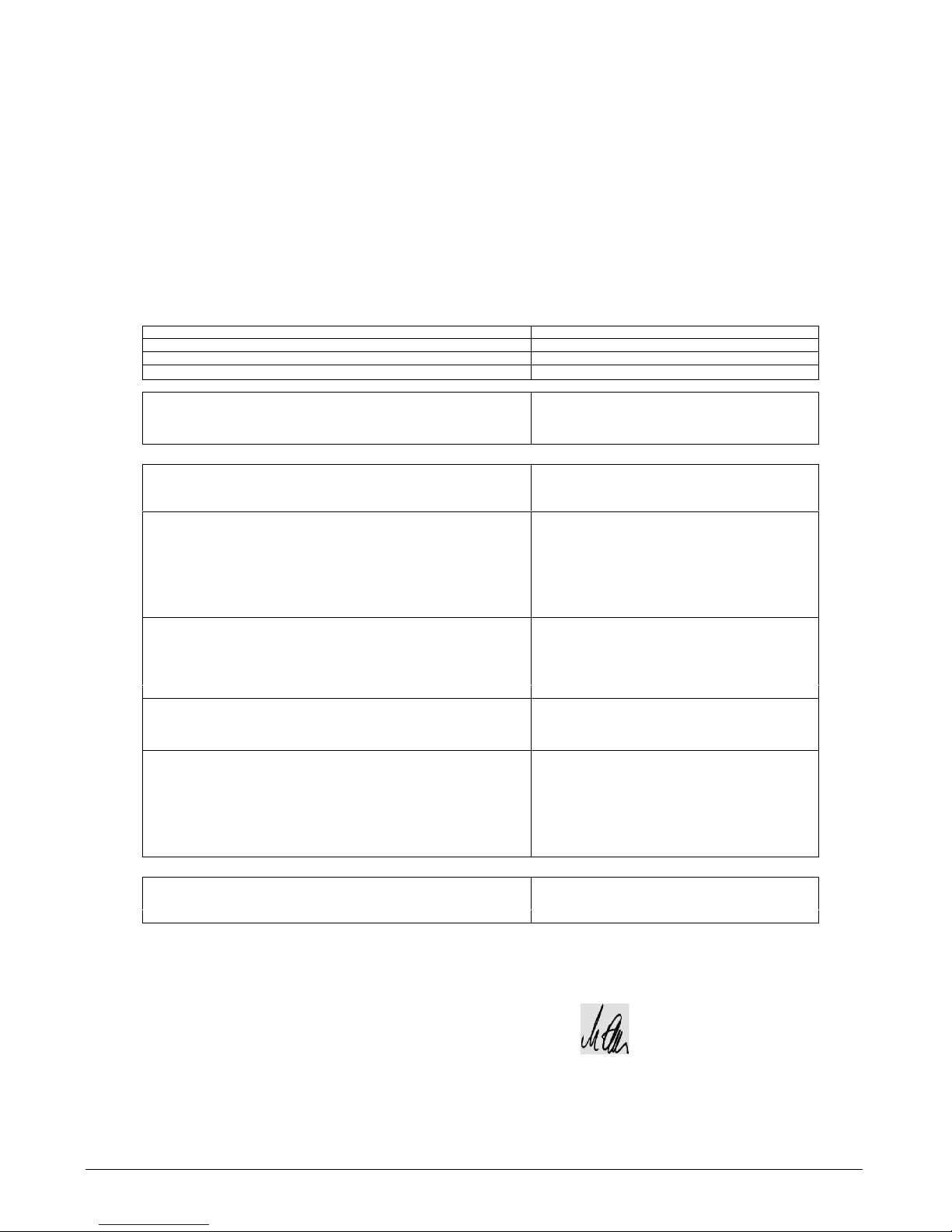
EG KONFORMITÄTSERKLÄRUNG
EC – DECLARATION OF CONFORMITY
DECLARTION CE DE CONFORMITE
DELLARCION DE CONFORMIDAD CE
Wir erklären in alleiniger Verantwortung, dass das Produkt auf das sich diese Erklärung bezieht mit der/den folgenden Normen
oder normativen Dokumenten übereinstimmt:
Herewith we declare bearing sole responsibility that the product referred in this declaration is in conformity with the following standards or
normative documents and regulations of the directive:
Nous declarons de notre seule responsabilite que le produit auquel se rapporte la presnte declaration est conforme aux normes ou aux
documents normatifs suivants :
Declaramos, con nuestra exclusiva responsabilidad, la conformidad del producto al que se refiere la presente declaracion la(s) norms(s)
Bezeichnung des Erzeugnisses
Sounder
Name of product Sound Generator
Titre Produit Sirenes
Nombre del producto Sirena electronica
Geräte- oder Typenbezeichnung
Equipment type or mark of equipment
Identification du produit
dHE
Nombre del aparato o del tipo
Bestimmung der Richtlinie
Nr. und Ausgabedatum der Norm(en)
Provisions of the directive No. and date of issue of the standard(s)
Désignation de la directive No. et date d´ émision de la/des norme(s)
Directiva aplicable N° y fecha de emisión de la(s) norma(s)
94/9/EG: Geräte und Schutzsyteme zur bestimmungsgemäßen
Verwendung in explosionsgefährdeten Bereichen
EN 50014:1997+A1+A2
94/9/EC: Equipment and protective system intended for use in EN 50018:2000
potentially explosive atmospheres EN 50019:2000
94/9/CE: Appareils et systéme de protection destinés á étre EN 50028:1987
utilisés en atmosphéres explosibles
94/9/CE : aparatos y sistemas de proteccón para uso en
atmósferas potenciaömente explosivas
EG Baumusterprüfbescheinigung
EC-type-examination certificate
PTB 03 ATEX 1232
Attestation examen CE
Certificado de examen CE
Benannte Stelle für die Bescheinigung
PTB, D-38116 Braunschweig
Notified body of the certificate
Organisme notifié de l` attestation
Organismo encargodo del certificado
Benannte Stelle für die Überwachung
TÜV-Österreich
Notified body of the inspection TÜV-A
Organisme notifié de contróle Krugerstraße 16
Organismo encargodo del examen A-1015 Wien
Kennummer
Inspection number / Numéro d`identification 0408
Número de examen
Hersteller /
Anschrift
J.Auer GmbH
Manufacturer / Factory address
Perfektastr. 102
Fabricant / Adresse
Fabricante / Direcciom
A-1230 WIen
Geschäftsfrührer:
Dipl. Ing. Michael Auer
Managing director / Direction Gérant / Gerente: .......................................................
(Name, Vorname / name, prename / apellido, nombre)
Wien 23.01.04
...................................... ................................... .......................................................
(
Ort
/ place / lieu / población) (
Datum
/ date / fecha )
(Rechtgültige Unterschrift)
Page 14
14
Technical Data
Type: dHE
Testing and certification:
Explosion category: CE0408
II 2 G EEx dem IIC T6
EC type examination certificate PTB 03 ATEX 1232
Housing degree of protection: IP 66 IEC 60529
Insulation class II
Time to wait before opening the device ≥ 15 minutes
after turning off operating power
Housing:
Housing material Plastic
Metal components Stainless steel V4A (ASTM 316)
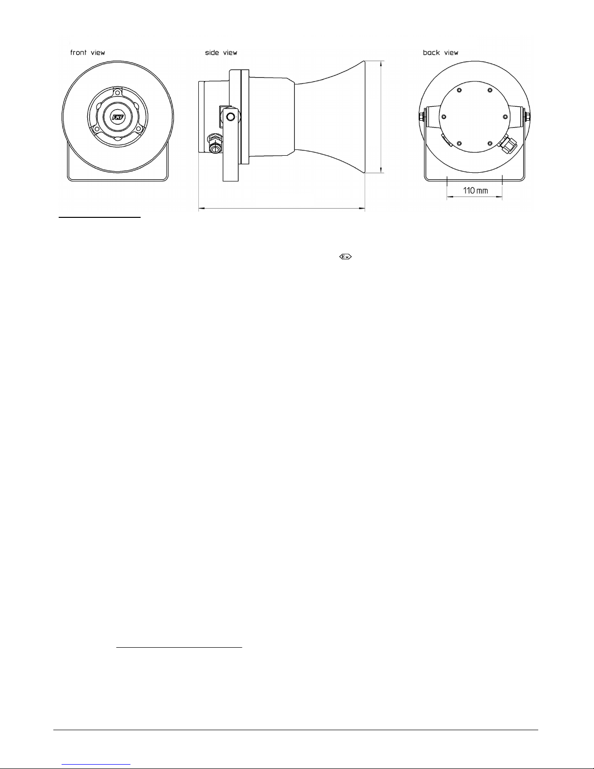
Dimensions ~ ∅ 278 x 365 mm
Weight ~ 5.9kg
Electrical connections: AC-version DC-version
Mains connection (terminals 1 - 2) L1, N L+, L-
- Operating voltage U
B
85 – 265VAC 21.6 - 75VDC
- Operating frequency 50 – 60Hz ---
- Power consumption P ≤ 12.5W
1)
≤ 2.5W
1)
(Tone1B, Max. sound pressure)
- Power consumption (mute) ≤ 2,5W ≤ 2.5W
- Power factor cos(ϕ ) 0.5 –0,7
2)
---
Control inputs (terminals 3 - 4 / 4 - 5) all versions
- Open circuit voltage U
O
≤ 5.5V
- Short circuit current I
O
≤ 0.6mA
- Number of sounders connected in parallel ≤ 32
- Wiring length ≤ 3000m Minimum cross-section 0.75 mm
2
1)
Power consumption is, to a great extent, independent of the operating voltage. It does,
however, depend on the signalling tone and the sound pressure lev el. The given v alue specifies
the highest power consumption of the device.
2)
The power factor of the alternating current version depends on the operating voltage. The
following formula determines the operating voltage dependent operating current I
B
of the device.
()
B
3
B
B
U1011,1794,0U
P
I
∗∗−∗
≈
−
For the DC version the following is valid: I
B
= P / UB
Dimensions
365 mm
278 mm
Page 15

15
Connecting terminals:
Clamping capacity, single wired,
fine-wired or multi-wired ≤ 2.5mm
2
(AWG 14)
Multiconductor connection maximum 2 x 1mm
2
3)
3)
Multiconductor connection is allowed at same cross-section and same conductor type, up to the
given value. In case of multi-wired conductors, wire-end sleeves are required. Pay attention to
EN 50019!
Acoustic data:
Signal tones 31 tones
Sound pressure ≤ 119 dB(A) at 1 m distance
Angle, -6 dB at 1000 Hz ≤ 130°
Operating conditions:
Mounting site Indoors and outdoors
Operating mode 100% continuous operation
Operating position any, although preferably such that the horn is
protected from intrusion of dust, rain water and
other pollution.
Ambient temperatures:
Operating -20°C to +40°C
Transport -25°C to +70°C
Storage -25°C to +70°C
ÄAeÄnderungen vorbehalten
Subject to change without notice
Sous réserve de modifications
Sujeto a modificaciones
Ä
J. Auer Fabrik Elektrischer Maschinen Gesellschaft m. b. H.
Perfektastr. 102
A-1230 Wien
Telefon (00431) 813 82 20
Telefax (00431) 815 99 51
http://www.auer-signal.com
e-mail: [email protected]
 Loading...