

Page 1

In-Vehicle
Wireless Observation System Kit
Owner’s/Installation Manual
WOS500
Audiovox Specialized Applications, LLC
23319 Cooper Drive
Elkhart, IN 46514
(219) 264-3135
Page 1 of 12
Rev. B 3/00
Page 2

Contents:
1) WOS500T Transmitter
2) WOS500R Receiver
3) Power Harness with Locking Connector
4) Hardware Package
Before Installation:
• This system operates on 12 Volts DC only, negative ground
• For maximum operating range, try to minimize the number of
obstacles between the transmitter and receiver units.
• This system broadcasts high-quality audio and video, using
directional antennas that must be orientated in certain
configurations for best results. The flat-pitted faces on the
receiver and transmitter have antenna which have been designed
to face each other.
• This system is NOT waterproof, and should not be used in a wet
or high humidity environment as this can cause system damage
or electrical shock.
• Do not stand on this product, or place things on this product.
Installation Instructions:
TRANSMITTER
1) Insert the power harness connector provided into the DC IN
socket on the rear panel.
2) Position the transmitter near the camera and mount using four of
the provided screws. Flat-pitted face should be facing toward the
front of the vehicle. See figure 1.
3) Connect the cable of the transmitter and camera.
RECEIVER
1) Position the receiver near the monitor and mount using the
remaining four provided screws. Flat-pitted face should be facing
toward the rear of the vehicle. See figure 1.
2) Connect the cable of the receiver to CA1 or CA2 of the monitor.
Page 2 of 12
Rev. B 3/00
Page 3

Transmitter and Receiver Placement:
Antenna
Vehicle Rear
Vehicle Front
Transmitter
Receiver
Figure 1
For best reception the transmitter and receiver must be aligned with the
flat-pitted faces back to back. The antenna in the receiver should face the
rear of the vehicle and the antenna in the transmitter should face the front
of the vehicle. RF signal can be picked up between the receiver and the
transmitter best by using this method.
Power Harness and Pinout:
58.5"
BLACK (-) WIRE
BLACK (-) WIRE
GND
RED (+) WIRE
SHRINK WRAP
BLACK (-) WIRE
RED (+) WIRE
+12 VOLT
IGNITION
RED (+) WIRE
(+12V Ignition)
Page 3 of 12
Rev. B 3/00
Page 4
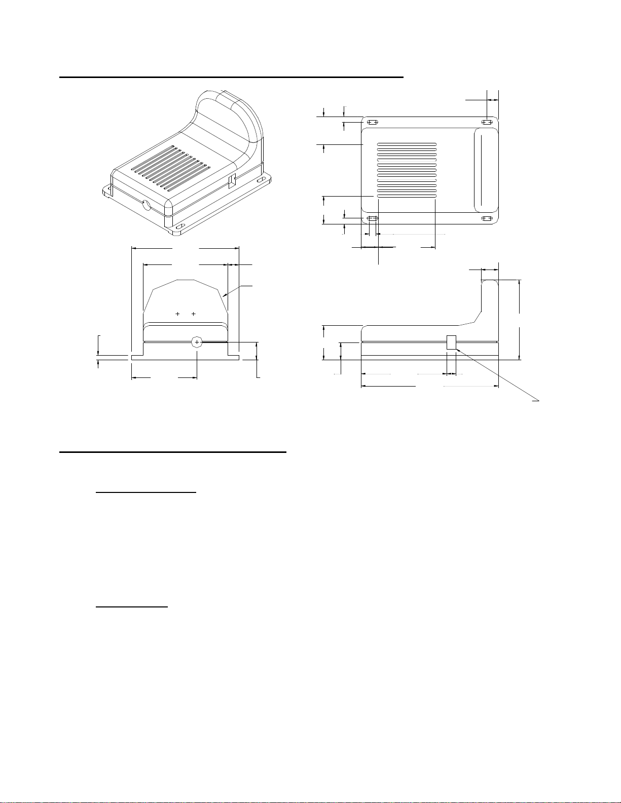
Receiver and Transmitter Dimensions:
0.195
0.078
1.833
1.443
1.112 0.303
0.195
R0.585
TYP. 2
0.478
0.478
0.098
0.585
0.293
0.293
0.098
TYP.
0.117 TYP.4
0.975
0.293
1.463
2.340
Transmitter Feature Only
0.156
1.365
Functions and Operation:
TRANSMITTER
1) Directional 2.4GHz antenna sends audio and video signals.
2) Power Connection
Pin 1- Ground- Black Wire
Pin 2- +12VDC ignition- Red Wire
3) Camera Connection to AOC75/AOC100 camera.
RECEIVER
1) Directional 2.4GHz antenna receives audio and video signals.
2) Monitor connection to AOM70/AOM53 monitor.
Make sure monitor is turned on to use the system. It may be
necessary to move the wireless transmitter and wireless receiver to
get the best operating conditions.
Page 4 of 12
Rev. B 3/00
Page 5

Receiver and Transmitter Features:
Transmitter View
• Connectable to the AOC75/AOC100 CDC camera
• 0 dBm Output Level
• Automatic electronic channel provides a memory
• Compact and lightweight design simplifies installation in most
vehicles.
• Built-in audio circuit for audio pickup
• Superior quality reception is due to FM rather than AM signal
modulation.
Power Connection
96"
Camera Connection
Receiver View
• Adapt high RF technical for EIA. This EIA would be used in the
United States, and other countries.
• Connectable with AOM70 Monochrome 7.0” Monitor/AOM53 5”
Monochrome monitor
• Channel Memory
• Fixed receiving antenna
Monitor Connection
12"
12"
120"
Built-In Power Connection
Red (+)
Black (-)
Page 5 of 12
Rev. B 3/00
Page 6

Receiver and Transmitter Connections:
Ground/Shield
Transmitter connection to camera
Arrow Locking Location
Audio
Power Connection
Video From
Camera
12V
96"
Camera Connection
Waterproof Camera Connector
Transmitter Cable Connector
To Transmitter
Grommet To Seal Through Vehicle Exterior
Receiver connection to monitor
EMI Ferrite Core
Video
Video Line
Shield
Ground
Cable Connector
End View
Wind Deflector
Installation Optional
+12V
Audio
Receiver Connection
Monitor Connection
A or B
End View
12"
12"
120"
Red (+)
Black (-)
Page 6 of 12
Rev. B 3/00
Page 7

Troubleshooting:
If the system does not function properly, check the following points
before contacting the service center.
• NO POWER- Power cable not plugged in or improper monitor
connection
• POOR RECEPTION- Improper antenna direction. See figure 1.
• PICTURE FLICKERING- Strong spotlight in the field of view
• DIM PICTURE, PICTURE TOO BRIGHT OR TOO DARK-
Improper brightness control setting on your monitor or lighting
source in the field of view.
• PICTURE SMALLER THAN SCREEN- Car battery voltage may
be too low.
Caution:
The Voyager Wireless System (WOS500) has been designed to
provide years of trouble free operation. To prevent fire or shock
hazard, do not expose this product to rain or moisture. This product
is not for use in a wet basement or in or around a swimming pool.
To avoid electrical shock, do not open the case of this product.
Operate this product using only a 12VDC power supply. The
servicing of this product should be left to qualified personnel only.
Be sure only one receiver is connected to one monitor.
Page 7 of 12
Rev. B 3/00
Page 8

Maintenance:
• Remove dust and dirt with a damp soft cloth.
• Heavier dirt should be removed with a damp cloth and a mild
detergent.
• Do not use strong cleaning agents containing gasoline, thinner,
benzene or alcohol.
Hardware Package Contents:
Quantity
8
Screw, #4 x 3/4" Pan Head
Phillips, Self-Drilliing
Page 8 of 12
Rev. B 3/00
Page 9

Accessory List:
Description Part Number Price
AVT-988 9” Color Television with Remote (12V) AVT988 $320.00
AVT-597 5” Color Television with Remote (12V) AVT597 $320.00
AVT-1498 13” Color Television with Remote
(12V)
AVP-7000 Video Cassette Player (12V) AVP7000 $270.00
BPA-501-12 4 Amp Adapter for use with AVT988 9” and AVT-1498 13” Televisions
AC2A- 2 Amp Adapter for use with AVT-597 5”
TV and AVP-7000 Video Cassette Player
Unified Remote Control 0892325 $45.00
VAC-21- 12 Volt Corded Vacuum VAC21 $35.00
AVF-1 12 Volt Rechargeable Flashlight AVF1 $25.00
HP-175 Headphones with Pivoting Ear Cup HP175 $11.75
HP-275 Headphones with Volume Control on
Cord
HP-375 Studio Quality Headphones HP375 $14.00
AVT1498 $350.00
0891412 $45.00
0891436 $35.00
HP275 $16.00
Unlike household electronics, all of our products have been specifically
tested for the mobile environment and are only available through ASA.
To order any of these products, please contact Audiovox Specialized
Applications at www.entertainment-to-go.com or 800-688-3135.
*Prices subject to change
Page 9 of 12
Rev. B 3/00
Page 10

Specifications:
Transmitter
Video Carrier Output Level 0 dBm
Operating Frequency 2410 MHz
Modulation FM- audio and video
Video Input Level 1 Vp-p
Audio Input Level 1 Vp-p
Power Supply 12VDC, (without camera)
Dimensions 3.7” W x 4.725” L x 2.165” H
Weight 300g
Camera Device AOC75/AOC100 (not supplied)
Receiver
Receiving frequency 2410 MHz
Video Output Level 1 Vp-p
Audio Output Level 0.1 Vrms
Video Carrier Input Level -75 to –30 mA
Power Supply 12VDC, 320 mA
Dimensions 3.7” W x 4.725” L x 2.165” H
Weight 300g
Monitor Device AOM70/AOM53 (not supplied)
*Specifications may change without notice
Page 10 of 12
Rev. B 3/00
Page 11

Notes:
______________________________________
______________________________________
______________________________________
______________________________________
______________________________________
______________________________________
______________________________________
______________________________________
______________________________________
______________________________________
______________________________________
______________________________________
______________________________________
______________________________________
______________________________________
______________________________________
______________________________________
______________________________________
______________________________________
______________________________________
______________________________________
______________________________________
______________________________________
______________________________________
______________________________________
______________________________________
______________________________________
Page 11 of 12
Rev. B 3/00
Page 12

Page 12 of 12
Rev. B 3/00
 Loading...