

Audiovox VD1400HT Owner's Manual
- 1 -
Important Safety Instructions
WARNI NG
The lightning flash with an arrowhead symbol, within
the equilateral triangle, is intended to alert the user to
the presence of uninsulated "dangerous voltage"
within the product's enclosure that may be of sufficient
magnitude to cause an electric shock.
The exclamation point within the equilateral triangle is
intended to alert the user to the presence of important
operating and maintenance (servicing) instructions
in this owner manual.
WARNING: TO REDUCE THE RISK OF ELECTRIC
SHOCK, DO NOT REMOVE COVER (OR BACK). NO
USER-SERVICEABLE PARTS INSIDE. REFER
SERVICING TO QUALIFIED SERVICE PERSONNEL.
WARNING:
TO PREVENT FIRE OR SHOCK
HAZARD, DO NOT EXPOSE THIS
APPLIANCE TO RAIN OR
MOISTURE.
CAUTION: TO PREVENT ELECTRIC SHOCK,
MATCH WIDE BLADE OF PLUG
TO WIDE SLOT , FULL Y INSERT .
Notes on Copyright
It is forbidden by law to copy, broadcast, show, broadcast on cable, play in public, rent copyrighted material
without permission.
Apparatus Claims of U.S. Patent Nos. 4,631,603; 4,577,216; 4,819,098 and 4,907,093 licensed for limited
viewing uses only.
DVD video discs are copy protected, and any recordings made from these discs will be distorted. This product
incorporates copyright protection technology that is protected by method claims of certain U.S. patents and
other intellectual property rights owned by Macrovision Corporation and other rights owners. Use of this
copyright protection technology must be authorized by Macrovision Corporation, and is intended for home and
other limited viewing uses only, unless otherwise authorized by Macrovision Corporation. Reverse engineering
or disassembly is prohibited.
On Placement
• Do not use the Unit in places which are extremely hot, cold, dusty, or humid.
• Place the Unit on a flat and even surface.
• Do not restrict the air flow of the Unit by placing it in a place with poor air flow, by covering it with a cloth, or
by placing it on carpeting.
FCC Information
This device complies with Part 15 of FCC Rules.
Operation is subject to the following two conditions:
(1) This device may not cause harmful interference, and
(2) This device must accept any interference received, including interference that may cause undesirable
operation.
On Safety
• When connecting or disconnecting the AC cord, grip the plug and not the cord itself. Pulling the cord may
damage it and create a hazard.
• When you are not going to use the Unit for a long period of time, disconnect the AC power cord.
On Condensation
• When left in a heated room where it is warm and damp, water droplets or condensation may form inside the
Unit. When there is condensation inside the Unit, the Unit may not function normally. Let the Unit stand for
1 to 2 hours before turning the power on, or gradually heat the room up and dry the Unit before use.
WARNING:
• Should any trouble occur, disconnect the AC power cord and refer servicing to a qualified technician.
• Do not place anything directly on the top of the Unit. Damage to the Unit can result.
This product
contains a low
power laser device.
The symbol for
Class II (Double
lnsulation)
CAUTION
INVISIBLE LASER RADIATION
WHEN OPEN AND INTERLOCKS
DEFEATED.
AVOID EXPOSURE TO BEAM
- 2 -
Important Safety Instructions
1. Read Instructions - All the safety and operating instructions should be read before the appliance is
operated.
2. Retain Instructions - The safety and operating instructions should be retained for future reference.
3. Heed Warnings - All warnings on the appliance and in the operating instructions should be adhered to.
4. Follow Instructions - All operating and use instructions should be followed.
5. Water and Moisture - The appliance should not be used near water - for example, near a bathtub,
washbowl, kitchen sink, laundry tub, in a wet basement, or near a swimming pool, and the like.
6. Carts and Stands - The appliance should be used only with a cart or stand that is
recommended by the manufacturer.
6A.An appliance and cart combination should be moved with care. Quick stops, excessive
force, and uneven surfaces may cause the appliance and cart combination to overturn.
7. Wall or Ceiling Mounting - The appliance should be mounted to a wall or ceiling only as
recommended by the manufacturer.
8. Ventilation - The appliance should be situated so that its location or position does not interfere with
its proper ventilation. For example, the appliance should not be situated on a bed, sofa, rug, or similar
surface that may block the ventilation openings; or, placed in a built-in installation, such as a book case
or cabinet, that may impede the flow of air through the ventilation openings.
9. Heat - The appliance should be situated away from heat sources such as radiators, heat registers,
stoves, or other appliances (including amplifiers) that produce heat.
10. Power Sources - The appliance should be connected to a power supply only of the type described in
the operating instructions or as marked on the appliance.
11. Grounding or Polarization - Precautions should be taken so that the grounding or polarization means
of an appliance are not defeated.
12. Power-Cord Protection - Power-supply cords
should be routed so that they are not likely to be
walked on or pinched by items placed upon or
against them, paying particular attention to cords
at plugs, convenience receptacles, and the point
where they exit from the appliance.
13. Cleaning - The appliance should be cleaned only
as recommended by the manufacturer.
14. Power Lines - An outdoor antenna should be
located away from power lines.
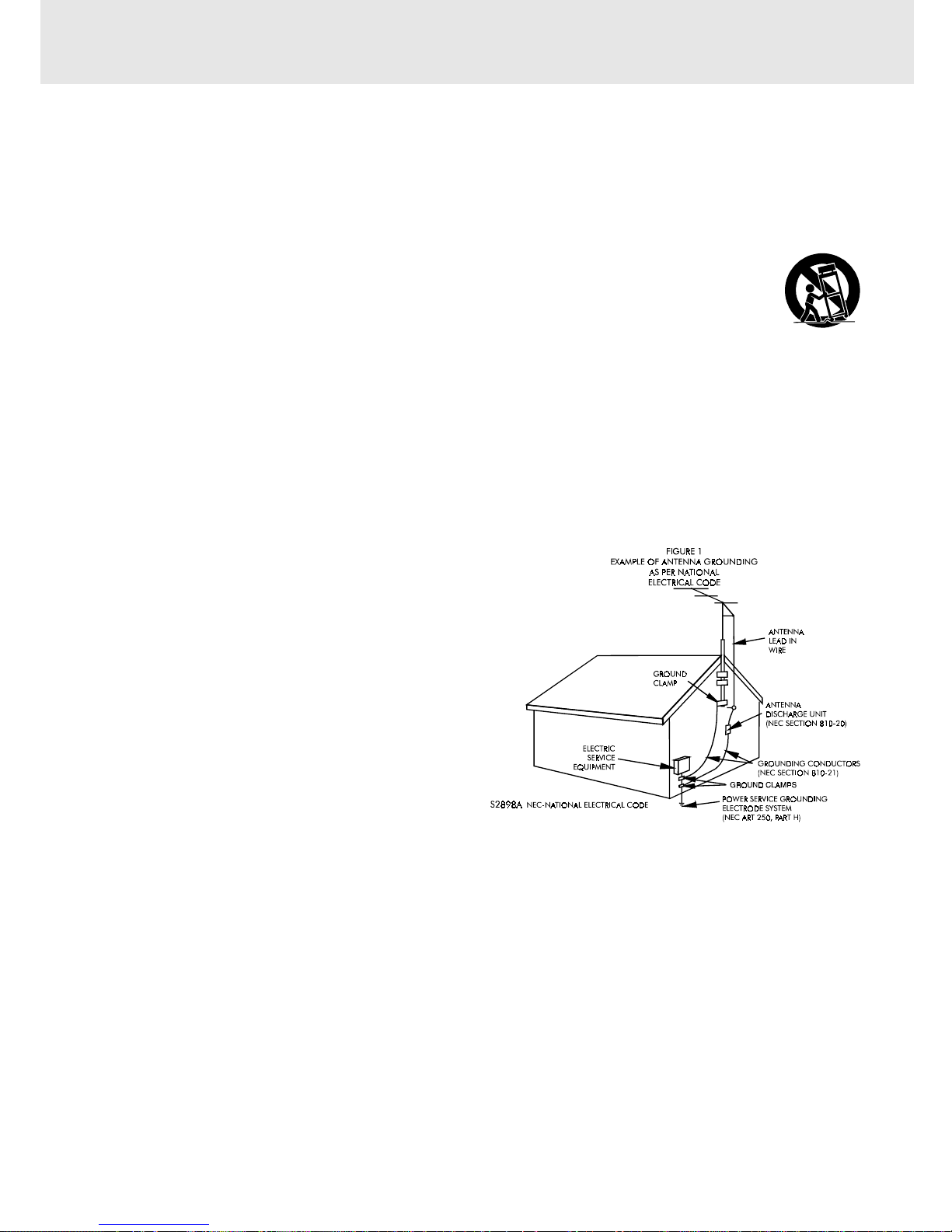
15. Outdoor Antenna Grounding - If an outside
antenna is connected to the receiver, be sure the
antenna system is grounded so as to provide
some protection against voltage surges and built
up static charges. Section 810 of the National
Electrical Code, ANSI/NFPA No. 70, provides information with respect to proper grounding of the mast
and supporting structure, grounding of the lead-in wire to an antenna discharge unit, size of grounding
conductors, location of antenna-discharge unit, connection to grounding electrodes, and requirements
for the grounding electrode. See Figure 1.
16. Nonuse Periods - The power cord of the appliance should be unplugged from the outlet when left
unused for a long period of time.
17. Object and Liquid Entry - Care should be taken so that objects do not fall, and liquids are not spilled,
into the enclosure through openings.
18. Damage Requiring Service - The appliance should be serviced by qualified service personnel when:
A. The power-supply cord or the plug has been damaged; or
B. Objects have fallen, or liquid has been spilled, into the appliance; or
C. The appliance has been exposed to rain; or
D. The appliance does not appear to operate normally or exhibits a marked change in performance; or
E. The appliance has been dropped, or the enclosure damaged.
19. Servicing - The user should not attempt to service the appliance beyond that described in the operating
instructions. All other servicing should be referred to qualified service personnel.

- 3 -
Table of Contents
Important Safety Instruction ..................... 1-2
Disc Formats ................................................ 5
Parts and Functions .................................. 6-9
Front Panel ................................................................. 6
Rear Panel .................................................................. 7
Using the Remote Control ........................................ 7
Remote Control ...................................................... 8-9
Display ......................................................... 10
Front Panel Display .................................................. 10
Display Information ................................................ 10
Connections .......................................... 11-18
Connecting your TV ................................................. 11
Cable TV Connections ............................... 12-15
For better reception of Radio .................................. 15
Connecting the speakers & subwoofer .................. 16
Positioning the speakers and subwoofer .............. 16
Connecting other equipment ................................ 17
Mounting rear surround speakers .......................... 18
Turning on the Unit and TV ...................................... 18
Power cord connection ........................................... 18
Adjusting the Sound ............................. 19-20
Playing a Disc ....................................... 21-24
Pausing playback (still mode) ............................... 21
Stopping playback ................................................. 21
To skip to a different track ...................................... 21
Fast Foward/Fast Reverse ..................................... 22
Slow-motion play ................................................... 22
Skip (Forward) ........................................................ 22
Zooming into an image ......................................... 22
Angle selection ....................................................... 23
Audio selection ....................................................... 23
Subtitle selection .................................................... 24
(Continued on next page)(Continued on next page)
(Continued on next page)(Continued on next page)
(Continued on next page)
IMPORTANT
This Unit does NOT allow
copying from DVD to VCR tape
CD / DVD programmable memory ............... 28
DVD programmable memory ................................. 28
Title/Chapter programmed playback ............. 28
CD programmable memory ................................... 28
Track programmed playback .......................... 28
Special Functions ................................. 25-27
Display function (DVD) .......................................... 25
GOTO function (DVD) ........................................... 25
Locating a specific title ......................................... 26
Locating a specific title/chapter/track .................. 26
Locating a specific time ......................................... 27
Angle setting ........................................................... 27
Audio setting .......................................................... 27
Subtitle setting ....................................................... 27
Repeat Playback ................................... 29-30
Repeating a title/chapter (DVD) ............................ 29
Repeating a single track/whole disc (CD) ........... 29
Repeating a specific section (DVD) ...................... 30
Playing MP3 and Picture File Disc......... 31-32
Playing a MP3 file disc ......................................... 31
Playing a Picture file disc .................................... 32
Playing a MP3/Picture file disc ............................ 32
Customizing the Function Settings ........ 33-41
LANGUAGE setting .................................................. 33
VIDEO setting ............................................................ 34
TV Shape .............................................................. 34
Video Output ....................................................... 35
Brightness ............................................................ 35
Edges .................................................................... 36
AUDIO setting ........................................................... 37
Digital Out ............................................................ 37
L/R speaker .......................................................... 37
Subwoofer ............................................................ 38
Surround Delay .................................................. 38
Center Delay ........................................................ 39
Pink noise ........................................................... 39
RATING setting ......................................................... 40
Password/Rating ............................................... 40
Factory Set .......................................................... 41
VCR Setup ............................................. 42-53
MENU screen ............................................................ 42
OSD (On Screen Display) ....................................... 42
How to display indicators ................................. 42
Setup (with Auto Clock Setting) ............................ 43
Setting the 3
4 Output Channel ............... 44
Mode Selection ................................................... 45
Channel Preset ......................................................... 46

- 4 -
Table of Contents
Adding Channel Memory/Erasing Channel
Memory ................................................................ 47
Clock .................................................................... 48-50
Auto Clock Setting ............................................ 48
Manual Clock Setting ......................................... 49
Automatic Daylight Saving-Time (D.S.T.)
adjustment ........................................................ 50
Language .................................................................. 50
VCR Playback ........................................ 51-53
Inserting a video cassette ............................... 51
Playback ..................................................................... 51
Fast forward and rewind ................................. 51
Video search ....................................................... 51
Slow motion playback ..................................... 52
Still picture and frame advance ....................... 52
Automatic tracking control system ................ 52
Manual tracking control ................................... 52
Blue screen noise elimination ........................ 52
Quick start with full loading mechanism ....... 53
Full automatic playback .................................... 53
Audio output mode ........................................... 53
VCR Recording ...................................... 54-60
Recording a TV programme ................................... 54
Without a cable box or digital satellite receiver
.............................................................................. 54
With a cable box or digital satellite receiver
.............................................................................. 54
To watch another TV programme while recording
.............................................................................. 54
Cassette erase protection ............................... 54
Recording speeds ............................................. 55
Recording Hi-Fi stereo sound ......................... 55
Recording MTS broadcasts .............................. 55
MTS/SAP recording ........................................... 55
Monitor output when receiving a SAP broadcast
.............................................................................. 56
Tape dubbing connection instructions ......... 56
Simple recording timer ...................................... 57
Changing the contents of the simple recording
timer .................................................................... 57
Cancelling the simple recording timer ........... 57
Recording with the timer ............................. 58-59
Confirming timer programmes ....................... 60
Cancelling timer programmes ........................ 60
Special Functions ...................................... 61
Recorded section Auto Repeat ........................... 61
Skip Search ............................................................ 61
Instant Replay ......................................................... 61
Radio Operation ......................................... 62
Tuning into a station manually ............................... 62
FM Stereo ............................................................. 62
Weak FM stations ............................................... 62
To search for a station automatically ................ 62
Presetting stations ............................................. 62
Tuning into a preset station .................................... 62
Language Code List for Disc Language ....... 63
Maintenance ................................................ 64
Cleaning Disc .......................................................... 64
Cleaning the Unit ................................................... 64
Important Note ....................................................... 64
Trouble Shooting Guide ........................ 64-66
- 5 -
The Unit can playback.
Region Management Information
Region Management Information: This Unit is designed and manufactured to respond to the Region
Management Information that is encoded on DVD discs. If the Region number printed on the DVD disc does
not correspond to the Region number of this Unit, this Unit cannot play that disc.
The region number of this Unit is 1.
Disc Function or Operation that is Not Available
When the symbol appears on the TV screen, it indicates that the function or operation attempted is not
available at that time. This occurs because the DVD disc manufacturer determines the specific functions.
Certain functions may not be available on some discs. Be sure to read the documentation provided with the
DVD.
6
+D=FJAH +D=FJAH+D=FJAH +D=FJAH +D=FJAH!
DVDs
[8cm(3")/12cm(5”) disc]
Notes on Unauthorized Discs
You may not be able to play back some DVD discs on this Unit if they were purchased from outside your
geographic area or made for business purposes.
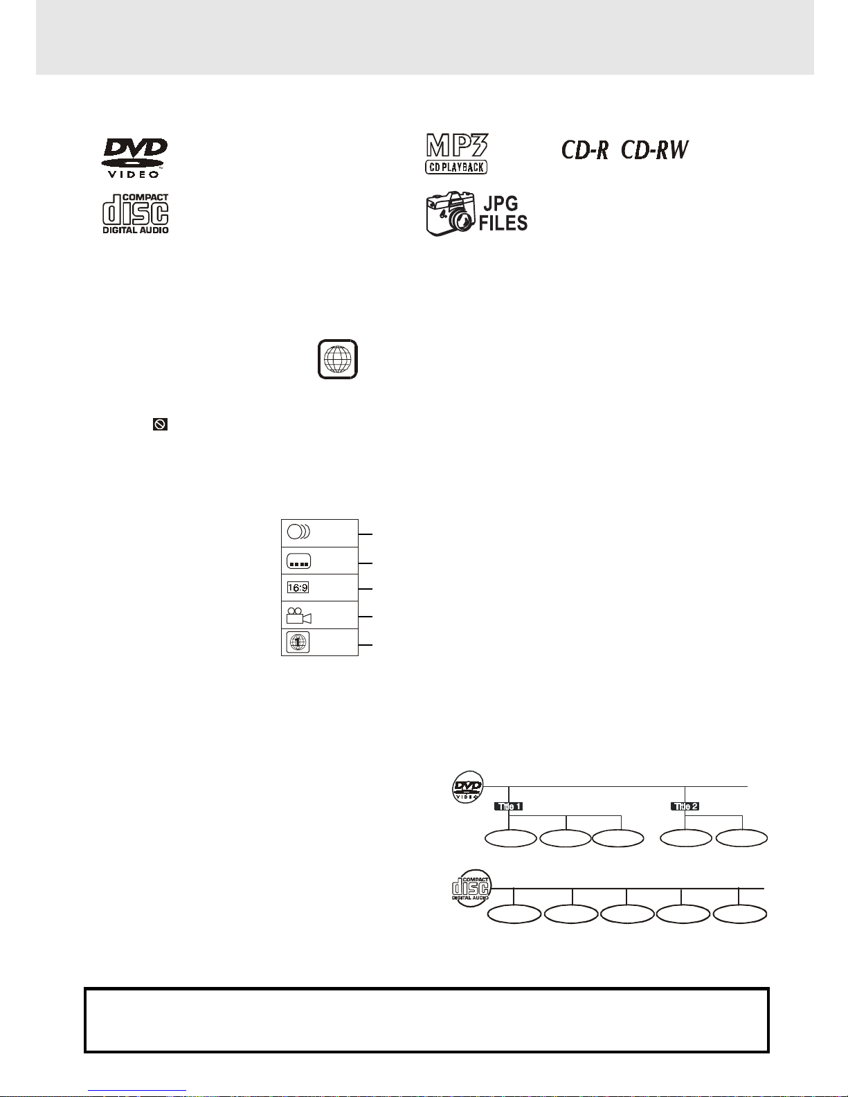
Title, Chapter and Tracks
• DVDs are divided into “titles” and “chapters”. If the
disc has more than one movie on it, each movie would
be a separate “title”. “Chapters” are sections of titles.
• Audio CDs are divided into “tracks”. A “track” is
usually one song on an Audio CD.
Note :
• Numbers identify each title, chapter, and track on a disc. Most discs have these numbers recorded on them,
but some do not.
Trac k 1 Tra ck 2 Track 3 Track 4 Track 5
Icons Used on DVDs
Sample lcons
Language selections for audio
Language selections for subtitles
Screen aspect ratio
Multiple camera angles
Region code indicator
2
2
2
1. English
2. French
1. English
2. French
Notes:
• This Unit supports 2-channel (L/R) audio and 5.1ch (Multi-channel) MPEG Audio 1/2 (only when the DIGITAL
AUDIO OUT coaxial jack is used for connection). It does not support 7.1 channel MPEG Audio Version 2.0.
• When playing back a CD-G (Graphics) or CD EXTRA disc, the audio portion will be played, but the graphic
images will not be shown.
Disc Formats
Compatible
Audio CDs
[8cm(3")/12cm(5”) disc]
- 6 -
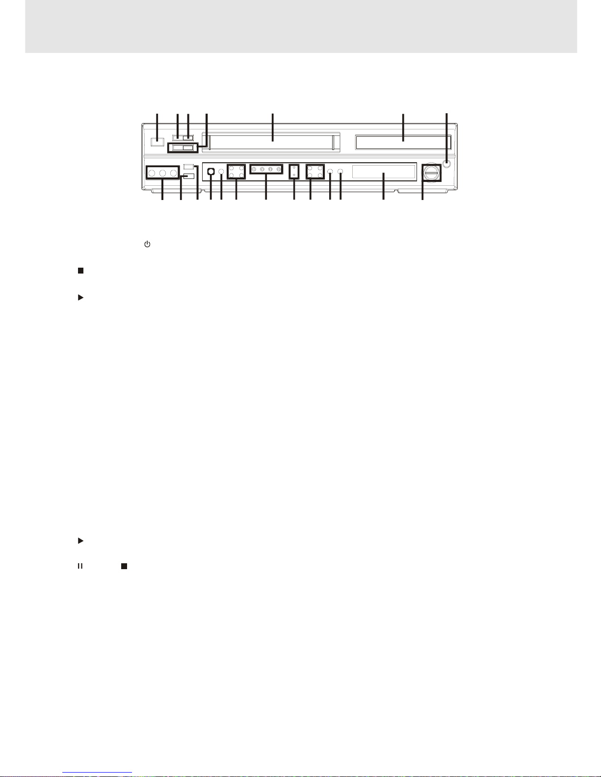
1) MAIN POWER/ STANDBY button
Turn the power on or off.
2) STOP button (for VCR)
Stop playing a disc.
3) PLAY button (for VCR)
Press to start or resume playback
4) CHANNEL button UP/ DOWN (for VCR)
Use to highlight selections on a menu screen and
adjust certain setting.
5) Video cassette compartment
Open tray by pushing TAPE EJECT button.
6) Disc tray
Open or close tray by pushing DVD OPEN/CLOSE
button. Place a disc on the disc tray, label side up.
7) DVD OPEN/CLOSE button
Use to open and close the disc tray.
8) VOLUME control
Change the loudness of the sound from the speakers
connected to the Unit.
9) Display window
Display system information.
10) FUNCTION button (DVD/RADIO/VCR)
Select the source.
11)
PLAY button (for DVD)
Press to start or resume playback
12)
PAUSE/ STOP/REW/F.FW button (for DVD)
Press to pause playback. Each time you press the
PAUSE button the picture advances one frame.
Press the PLAY button to resume playback.
Stop playing a disc.
Fast reverse and forward playback.
13) MAIN POWER/ STANDBY indicator
When the Unit is turned on by pressing the MAIN
POWER/STANDBY button, the light will illuminate
Front Panel
a few seconds. If you press the POWER button on
the remote control, the Unit will turn off and go into
standby mode. The light will continue to illuminate.
14) VCR POWER/TIMER/VCR/REC indicator
VCR POWER : This indicator lights up whenever the
VCR is turned on.
TIMER : This indciator lights up when the VCR is set
for timer recording. Simple Recording Timer and
Recording with the Timer.
VCR : This indicator lights up when selecting "VCR"
by using TV/VCR.
REC : This indicator lights up during recording and
flashes during REC-Pause.
15) SET/MENU/REW/F.FWD button (for VCR)
SET : Confirm selections on a VCR menu screen.
MENU : Use to select various screen functions.
REW : Fast reverse playback.
F.FWD : Fast forward playback.
16) REC button (for VCR)
Record a programme from TV or other sources
(except DVD).
17) VCR ON/OFF button
Turn the VCR on or off.
18) TAPE EJECT button (for VCR)
Use to eject the tape.
19 ) Remote sensor
Accept the remote control unit signals.
20) VIDEO IN/AUDIO IN (L/R) jacks (AV 2 IN)
VIDEO IN : Connect a cable coming from the video
out jack of a camcorder, another VCR, or an audio
visual source here.
AUDIO IN (L/R) : Connect audio cables coming from
the audio out jacks of a camcorder, another VCR, or
an audio source here.
Pa rts and Functions
Note:
Screen saver - If no button is pressed within 2 minutes, the screen save function will activate for DVD only, If you want
to return to the normal screen, press any button.
1234 5 6 7
8
9101112131516 14
1718
19
20
(Continued on next page)(Continued on next page)
(Continued on next page)(Continued on next page)
(Continued on next page)
- 7 -
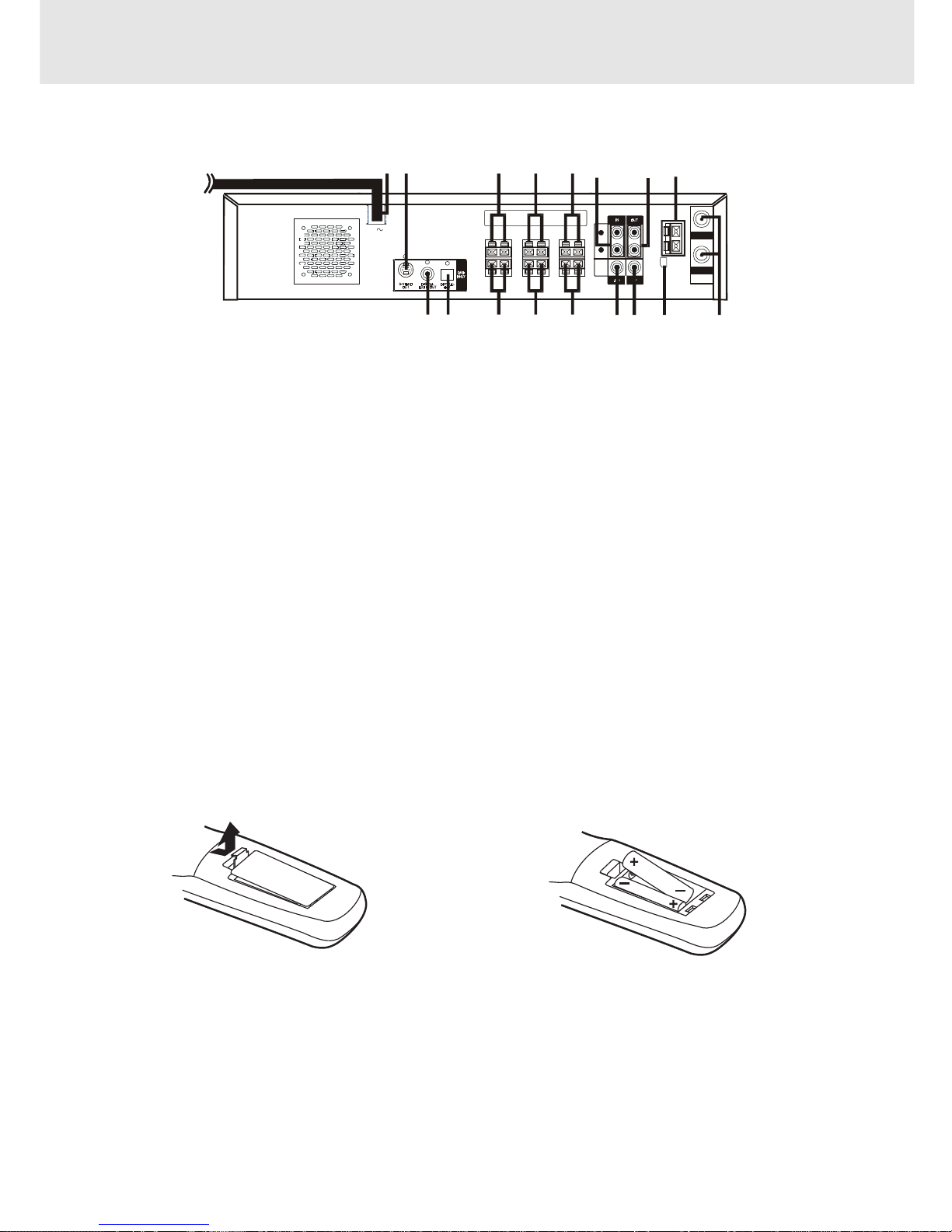
Rear Panel
21) Power cord
22) S-VIDEO (DVD) output jack
23) Right Front speaker terminals
24) Centre speaker terminals
25) Left Front speaker terminals
26) AV1 IN (AUDIO) jacks
27) Left/Right AUDIO OUT jacks
28) FM ANTENNA jacks
29) VHF/UHF/CATV IN/OUT jacks
30) AM LOOP ANTENNA terminal
31) TV OUT (VIDEO) jack
32) VIDEO IN (VCR) jack
33) Left Rear speaker terminals
34) Subwoofer speaker terminals
35) Right Rear speaker terminals
36) OPTICAL OUT jack (DVD)
37) DIGITAL AUDIO OUT jack (DVD)
(Continued on next page)(Continued on next page)
(Continued on next page)(Continued on next page)
(Continued on next page)
R
L
AUDIO
VIDEO
AM
LOOP
ANT.
FM AN T.
300 ()
Ω
IN
OUT
VHF/UHF/
CATV
AC
21
22 23 24 25
26
27 28
293031323334353637
Parts and Functions
To install Batteries
1.Open the battery door.
Battery Replacement
When batteries become weak, the operating distance of the Remote Control is greatly reduced and you will
need to replace the batteries.
Notes:
• If the Remote Control is not going to be used for a long time, remove the batteries to avoid damage caused
by battery leakage corrosion.
• Do not mix old and new batteries. Do not mix ALKALINE, standard (CARBON-ZINC) or rechargeable
(NICKEL-CADMIUM) batteries.
2. Insert two "AA" or UM-3 size batteries.
Using the Remote Control
• Point the Remote Control at the REMOTE SENSOR located on the Unit.
• When there is a strong ambient light source, the performance of the infrared REMOTE SENSOR may be
degraded, causing unreliable operation.
• The recommended effective distance for remote operation is about 16 feet (5 meters).
- 8 -
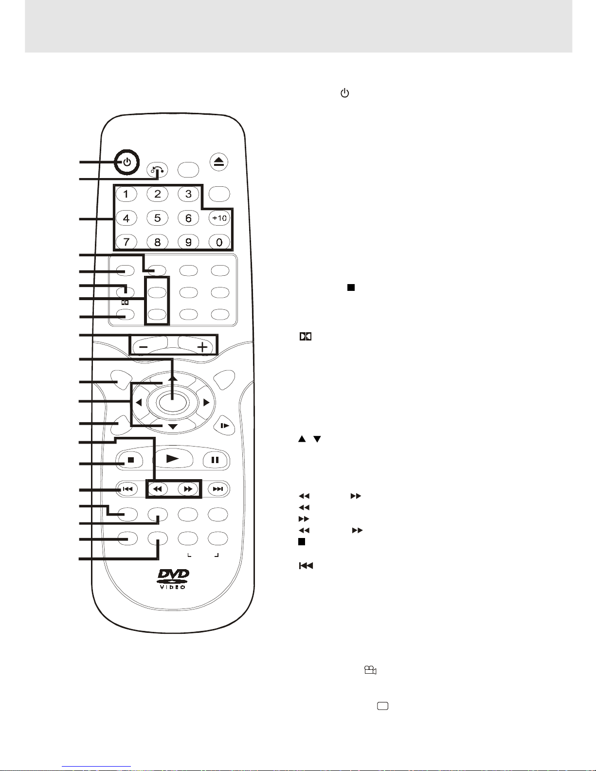
Pa rts and Functions
1) POWER / button
Turns the Unit on and puts it in standby mode.
2) RETURN button
Return to the normal operation after using the SETUP menu.
3) Number (0 - 9) and AM/PM (+10) buttons
Use when creating programs, and entering a parental level
password. To select numbers over 9, press +10 button and
then the second no. for example, to enter 18, press +10 and
then 8.
AM/PM : Select AM or PM during time setting.
4) 5.1 Ch button
Switch speaker output to 5.1 channel mode. (All speakers +
subwoofer)
5) MEMORY button
Enter the number of a selected chapter or track.
Enter the number of a selected station.
Enter the number of a selected channel.
6) VCR STOP button
Stop playback.
7) CHANNEL +/- buttons
Select the desired channel.
8)
PRO LOGIC button
In AV_IN mode, switches to Dolby Pro Logic mode for VHS
tapes encoded with Dolby Pro Logic.
9) VOLUME (+ / -) buttons
Adjust the volume.
10) ENTER button
Confirm selections on a menu screen.
11) SETUP button
Selects the SET UP menu screen.
12)
/ CURSOR buttons
Use to highlight selections on a menu screen and adjust
certain settings.
13) VCR ON/OFF button
Turns the VCR on and off.
14) TUNING buttons
: Fast reverse playback of DVDs/VCRs.
: Fast forward playback of DVDs/VCRs.
TUNING : Scan all available radio stations.
15) STOP button (for DVD/VCR)
Stop playback.
16) PREV button (for DVD/VCR)
Move reverse through titles, chapters or tracks on a disc.
Tune to the presetted stations.
Set a reverse video search time.
17) CLEAR button
Clear input selections and cancel certain playback functions.
18) DISPLAY button
Change disc status information displayed on the TV.
Change the screen as your desired.
19) ANGLE button
Switch the camera angle of the video presentation when
scenes with multiple camera angles are recorded on a DVD.
20) SUBTITLE button
.....
Select one of the subtitle languages programmed on a DVD.
(Continued on next page)(Continued on next page)
(Continued on next page)(Continued on next page)
(Continued on next page)
Remote Control
POW ER
RETURN
OPEN/
CLOSE
FUNCTION
GOTO
AM/PM
VOLUM E
SETUP MENU
ENTER
STOP
PREV
CLEAR
ANGLE SUBTITLE FM MODE BA ND
A-B
DISC
DISPLAY ZOOM AUDIO
TUNING NEXT
PLAY
PAUS E
REPEAT
CH+
CH- SP .EP
INPUT TV/VCR
REC
MEMORY SOUND
PRO LOGIC
2.1 CH5.1 CH
SLOW
VCR STOP
VCR
ON/OFF
1
2
3
4
5
6
7
8
9
10
11
12
13
14
15
16
17
18
19
20
- 9 -
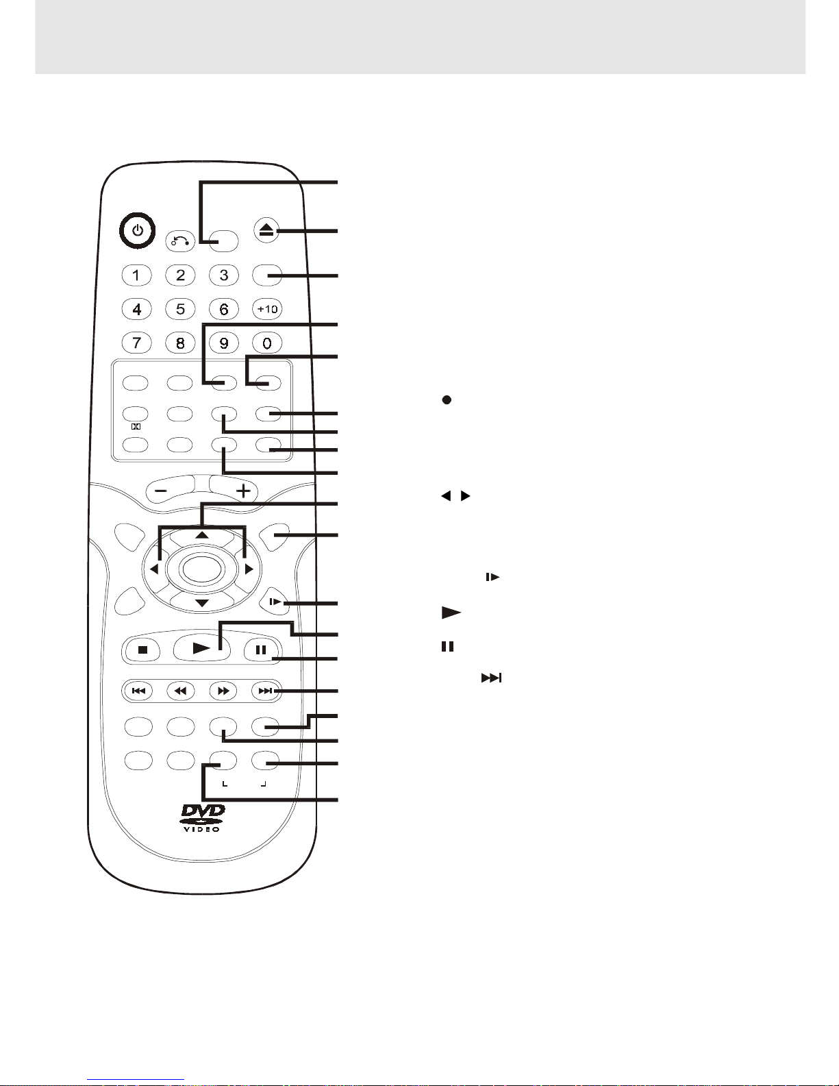
21) FUNCTION button
Display the FUNCTION screen where you can check
or change various setting.
22) OPEN / CLOSE button (for DVD)
Use to open or close the disc tray.
23) GOTO button
Skip directly to a specific location on a DVD disc.
24) 2.1 CH button
Switch speaker outputs to 2.1 channel. (Front left/right
speakers + subwoofer)
25) SOUND button
Selects sound balance and tone controls for adjustment
with the cursor buttons.
26) TV/VCR button
Use to select TV or VCR position.
27) INPUT button
Dub video material from another video device.
28)
REC button (for VCR)
Record a programme from TV or other sources (except
DVD).
29) SP • EP button
Select a recording speed (SP=standard play,
EP=extended play).
30)
/ CURSOR buttons
Use to highlight selections on a menu screen and
make adjust certain settings.
31) MENU button
Open and close DVD's menu.
32) SLOW
button (for DVD/VCR)
Perform slow forward playback.
33)
PLAY button (for DVD/VCR)
Start playback.
34)
PAUSE button (for DVD/VCR)
Pause playback, frame advance.
35) NEXT button (for DVD/VCR)
Move forward through titles, chapters or tracks on a
disc.
Tune to the presetted stations.
Set a forward video search time.
36) AUDIO button
Select one of the audio soundtracks programmed on
a DVD or selects the audio output mode on a AUDIO
CD.
37) ZOOM button
Zoom into an image.
38) BAND/REPEAT-DISC button
Switch between AM or FM.
Repeat chapter or title of a DVD.
Repeat single track or whole CD.
39) FM MODE / REPEAT A - B button
Set FM MODE to FM STEREO for FM stereo sound or
to FM MONO for mono sound.
Perform point-to-point repeat playback on a DVD or
CD.
Parts and Functions
Remote Control
POW ER
RETURN
OPEN/
CLOSE
FUNCTION
GOTO
AM/PM
VOLUM E
SETUP MENU
ENTER
STOP
PREV
CLEAR
ANGLE SUBTITLE FM M O DE BAND
A-B
DISC
DISPLAY ZOO M AUDIO
TUNING NEXT
PLAY
PAUS E
REPEAT
CH+
CH- SP .E P
INPUT TV/VCR
REC
MEMORY SOUND
PRO LOGIC
2.1 CH5.1 CH
SLOW
VCR STOP
VCR
ON/OFF
21
22
23
24
25
26
27
28
29
30
31
32
33
34
35
36
37
38
39
- 10 -
Region (Local) Number Error Indicator
If the region (local) number of the disc that you attempt to play differs from the region number of the Unit, "Invalid Region"
appears on the TV screen. (The disc cannot be played).
If no disc is loaded
when the Main Unit
is switched on.
Tray open
Tray closed
Loading
Stopped
Playing
Paused
Fast forward
Fast reverse
Slow
Repeat A - B
Remarks
"
" appears when the tray is closed and:
1)There is no disc in the tray.
2)The disc type is not playable in this Unit.
3) The disc is not loaded correctly (upside-down, etc.)
The display changes to show
other indicators (total time, etc.)
Freezes the image on the screen or pauses audio playback.
The display changes to show other indicators (total
time, etc.)
Does not function for Audio CDs.
Repeat a specific section.
The operation is not permitted by the DVD Unit or the
disc.
TV Screen
Unit Display
No Disc
Stop
Play
Pause
x 2
x 2
x 1/2
/
Loading...
A-B
B
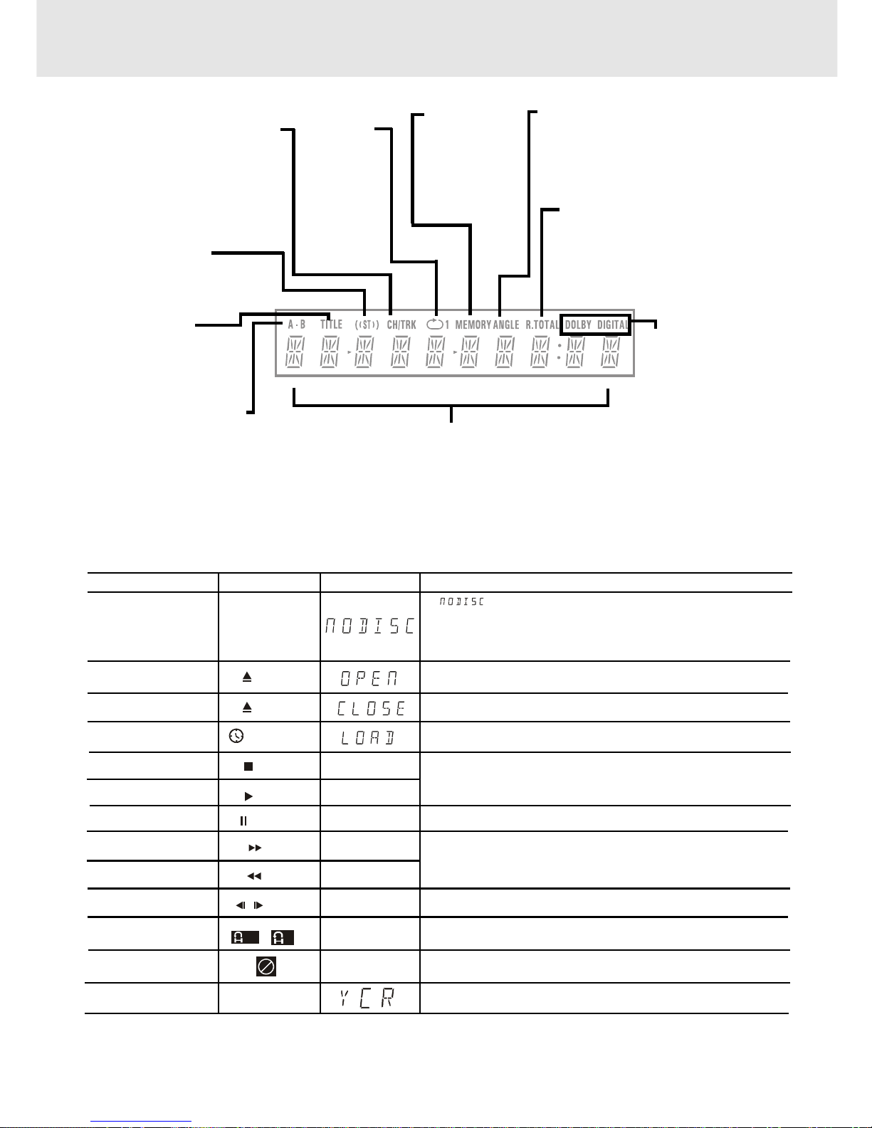
ANGLE indicator
Appears when multiple camera angles
are recorded in the section of the DVD
that is currently playing.
TITLE indicator
When a DVD is loaded in
the Unit, this indicator
appears along with the
title number.
CHAPTER / TRACK indicator
When a DVD is loaded in the
Unit, this indicator appears
along with the chapter number.
When a Audio CD is loaded in
the Unit, this indicator appears
along with the track number.
DOLBY DIGITAL
indicator
Displays while Dolby
Digital sound
processing is being
performed or when
the loaded disc
contains Dolby
Digital sound
OPERA TION indicator
Indicates the operation status of the disc and Unit.
REPEAT 1
playback
indicator
Displayed
during
repeat
playback.
Display
Front Panel Display
Display Information
The DVD displays the information shown below on the TV screen and on the Unit's DVD display depending
on the operation status.
Display Examples
Open
A -
R. T O TAL(REMAIN.TOTAL)
indicator
Indicates the elapsed playback time
of the disc. With some discs, this area
also shows the total play time of the
disc when playback is stopped.
REPEAT A-B playback
indicator
Displayed during repeat
playback.
MEMORY
indicator
Displayed
during
programmed
playback.
Close
STEREO indicator
Tune into a station. "((ST))"
will appear when an FM
broadcast is in stereo.
Turn on VCR
In VCR mode.
- 11 -
Connections
(continued to next page)(continued to next page)
(continued to next page)(continued to next page)
(continued to next page)
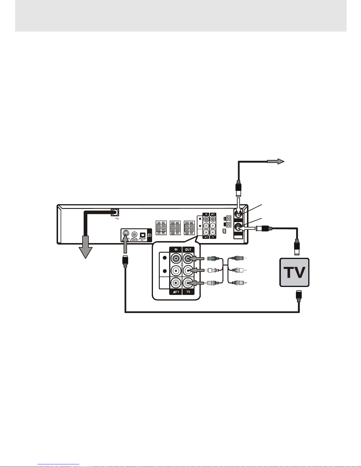
1. Connecting to your TV
The Unit can be connected to your TV in several different ways, depending on the design of your TV.
1. Connect the TV antenna (coaxial cable) to the input jack on the unit.
2. Attach one end of the supplied coaxial cable to the output jack on the unit, and the other end of the cable to the
input jack on your TV.
Alternate Connections:
1. If your TV has Audio/Video inputs, you can also connect the unit to your TV using the supplied Audio/Video cord.
2. If your TV is equipped with an S-Video input, you can utilize the S-Video jack to connect the unit to your TV with
an S-Video cord (not supplied) instead of the yellow video cable. Please note that the S-Video and coaxial cable
connection will only carry the video signal from DVD playback. VCR playback will still require you to use the coaxial
cable connection.
To Wall Outlet
When you connect this system
to your TV, be sure to turn off
the power and unplug both
units from the wall outlet before
making any connections.
S-Video cable (not supplied)
Audio/Video cable
(supplied)
(Red)
(White)
(Yellow)
(Red)
(White)
(Yellow)
To Audio IN
To Video IN
Coaxial cable
(supplied)
CATV or
ANTENNA
Coaxial cable
(not supplied)
ANTENNA IN
(antenna or cable input)
AM
LOOP
ANT.
FM ANT.
300
()
Ω
IN
OUT
VHF/UHF/
CATV
AC
R
L
AUDIO
VIDEO
R
L
AUDIO
VIDEO
TV OUT
Note:
• When playback DVD via coaxial cable to TV alone, there will be no audio output from the TV. i.e. Sound comes
from 5 speakers plus the subwoofer only.
- 12 -
Connections
(continued to next page)(continued to next page)
(continued to next page)(continued to next page)
(continued to next page)
Cable TV Connections
Your VCR is capable of receiving the following non-scrambled channels.
• Scrambled channels can be received with the cable box supplied by your cable TV company.
Preparation
Set the 3 4 Output Channel of the VCR to 3 or 4.
See Setting the 3
4 Output Channel.
First check your TV/CATV system
Step 1: Is your TV cable compatible with the VCR?
• YES Go to Step 2
• NO
Go to Step 3
Step 2: Does your CATV system have some or all channels scrambled?
• YES
Go to
• NO Go to
Step 3: Does your CATV system have some or all channels scrambled?
• YES
Go to
• NO Go to Step 4
Step 4: Choose the type below.
• Basic connection (only for descrambled CATV signals.)
Go to - or
• To watch a CATV programme while recording a TV programme by using the A/B switch. Go to
A.
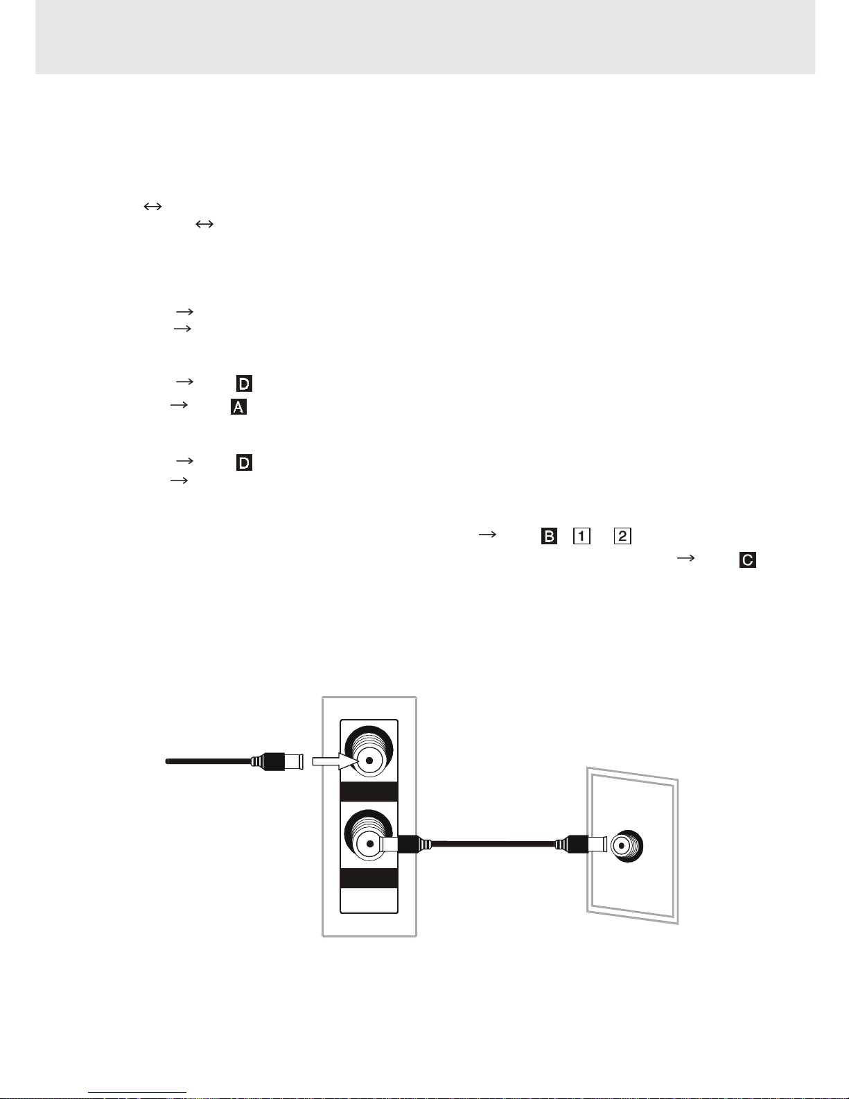
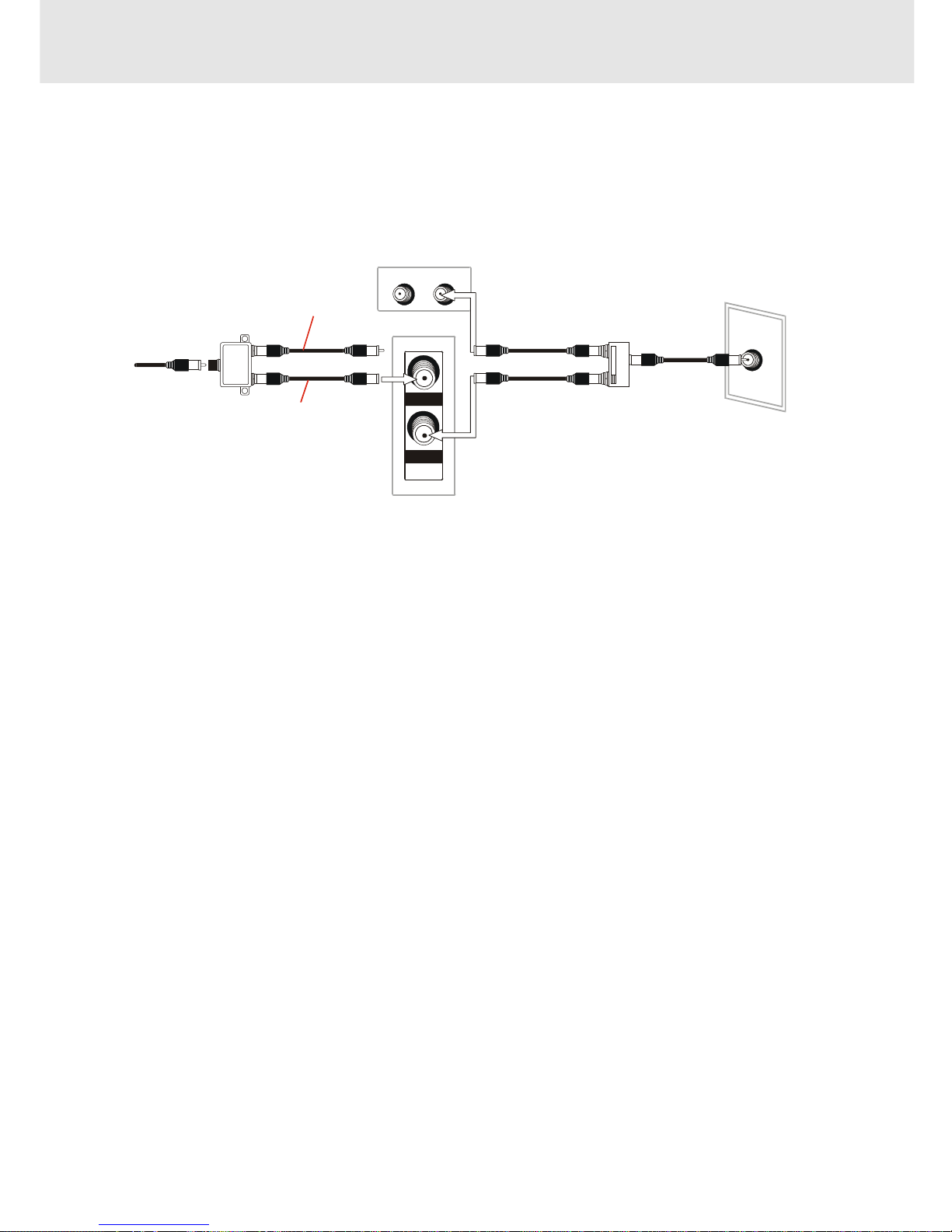
Connection without a cable box
Connect as shown. Then plug in the power cords of the TV and cable box.
Rear of Unit
From CATV system
IN
OUT
VHF/UHF/
CATV
TV Rear
ANT/CABL E
Coaxial cable (supplied)
- 13 -
Connections
(continued to next page)(continued to next page)
(continued to next page)(continued to next page)
(continued to next page)
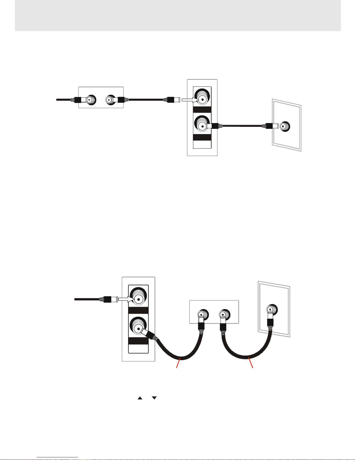
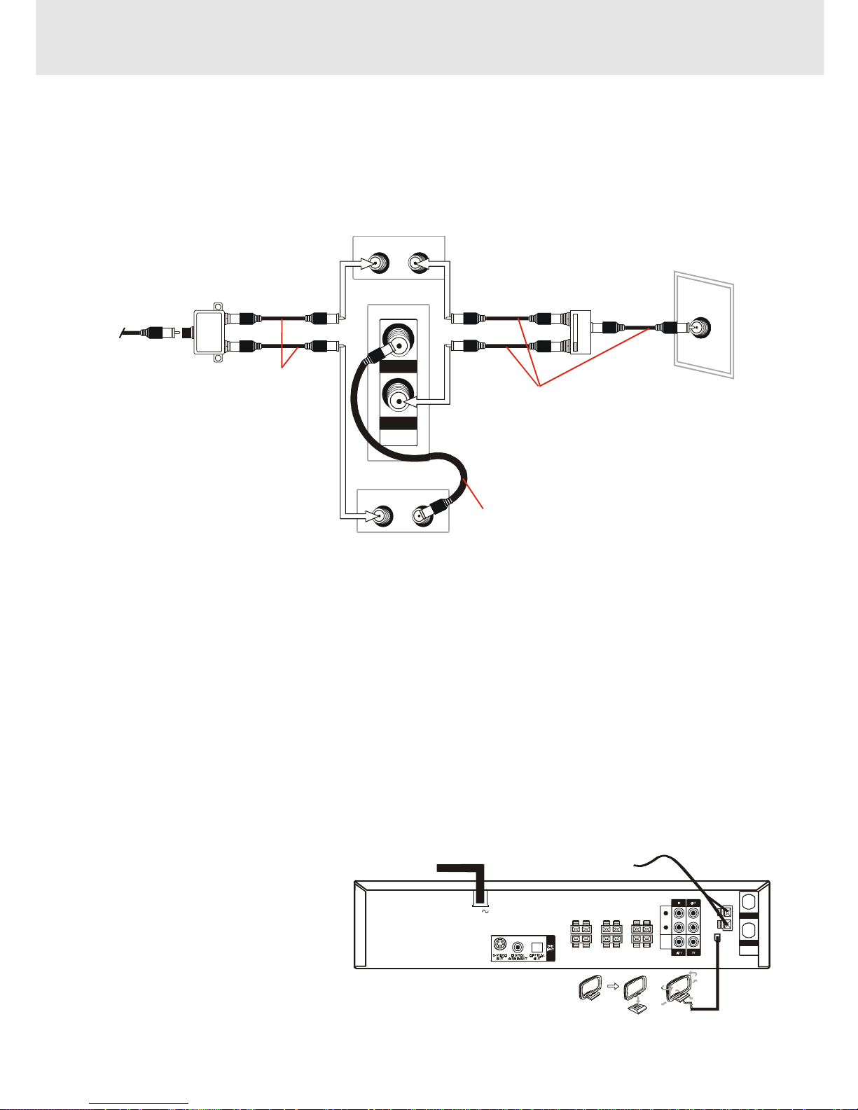
B.
Connection with cable box
1.
Connect as shown. With this connection, it is possible to record descrambled CATV signals. Then plug in the
power cords of the TV and cable box.
Rear of Unit
Cable Box
From
CATV
system
IN
OUT
VHF/UHF/
CATV
Coaxial cab le (No t su pplied)
IN OUT
TV Rea r
ANT/CABLE
Coaxial cable (supplied )
2.
Connect as shown. With this connection, it is not possible to record CATV programmes which have been
scrambled, but is possible to record one channel and watch the other one. Then plug in the power cords of the
TV and cable box.
TV Rear
ANT/CABLE
Rear of Unit
From CATV system
IN
OUT
VHF/UHF/
CATV
Coaxia l c able (Not supplie d )
Cable Box
IN OUT
Coaxial cable (supplied)
Notes:
• If the cable box is turned off, it will not output any signals, thus making it impossible to record or view a programme
from the CATV system.
• In the case of the above connections, it is not possible to change channels using the remote control. Only the
cable box can be used to change channels.
• Only one channel at a time can be programmed for recording programmes with the timer. It is not possible to
watch a TV programme different from the one being recorded.
• Depending on which terminals the TV has, a separate combiner (mixer) or separator (splitter) may be necessary.
Notes:
• With the above connection, CURSOR
or button of the VCR or the numbered b uttons on the remote control
can be used to select channels.
• Depending on which terminals the TV has, a combiner (mixer) or separator (splitter) may be necessary.
• To record one channel and watch another, the VCR must be set to the TV mode.
- 14 -
Connections
(continued to next page)(continued to next page)
(continued to next page)(continued to next page)
(continued to next page)
C.
Connection with cable box, A/B switch and splitter
By using an A/B switch or splitter, it is possible to switch between the cable box and the VCR output.
For example, while recording a TV programme with the VCR, it is possible to watch a CATV programme (including
descrambled programmes) using the A/B switch.
• Connect as shown. Then plug in the power cords of the TV and cable box.
Rear of Unit
From
CATV
system
IN
OUT
VHF/UHF/
CATV
Coaxial cable (Not supplied)
Splitter
(Not supplied)
Cable Box
IN OUT
Coaxial cable (supplied)
TV Rear
ANT/CABLE
A/B switch
(Not supplied)
A
B
Using the A/B Switch
1.Set the A/B switch to the “A” position in the following situations.
• To watch a cable TV programme while recording another programme.
• To watch a scrambled cable TV programme.
• To watch a cable TV programme when the VCR is turned off.
Notes:
• Use the cable box to change channels.
• If you turn off the cable box, you cannot watch a CATV programme.
2.Set the A/B switch to the “B” position in the following situations.
• To playback a cassette on the VCR.
• To watch a programme which is being recorded with the VCR tuner.
• To watch a programme using the VCR tuner.
- 15 -
Connections
(continued to next page)(continued to next page)
(continued to next page)(continued to next page)
(continued to next page)
D.
Connection with two cable boxes, A/B switch and splitter
The following connection is necessary to record a cable TV programme (even those scrambled by a cable
company) while watching another cable TV programme. The following connection requires two cable boxes, a 2way splitter and an A/B switch.
• Connect as shown. Then plug in the power cords of the TV and cable box.
Rear of Unit
From
CATV
system
IN
OUT
VHF/UHF/
CATV
Coaxial cable
(Not sup plied)
Coaxial cable (Not supplied)
Splitter
(Not sup plied)
Cable Box 1
Cable Box 2
ININOUT
OUT
TV Rear
ANT/CABLE
A/B switch
(Not sup plied)
A
B
Coaxial cable (supp lie d)
Using the A/B Switch
1.Set the A/B switch to the “A” position in the following situations.
• To watch a cable TV programme while recording another programme.
• To watch a cable TV programme when the VCR is tur ned off.
2.Set the A/B switch to the “B” position in the following situations.
• To playback a cassette on the VCR.
• To watch a programme being recorded , or to change (or watch) channels with the cable box 2. The output
channel of the cable box 2 and the VCR must be the same.
Notes:
• If you turn off the cable box, you cannot record or view a CATV programme.
• If you have questions regarding any connection procedure, please contact your cable company.
FM
Connect FM antenna (supplied) to the
FM ANTENNA jacks.
AM
Connect the AM loop antenna
(supplied) to the AM LOOP ANTENNA
terminals. Rotate the AM loop antenna
to obtain the best reception.
NOTE: Position this AM loop antenna
as far away as possible from this
system and from the TV.
2. For better reception of Radio
R
L
AUDIO
VIDEO
AM
LOOP
ANT.
FM ANT.
300
()
Ω
IN
OUT
VHF/UHF/
CATV
AC
FM ANTENNA
AC POWER CORD
AM (MW) LOOP ANTENNA (SUPPLIED)
- 16 -
Connections
(continued to next page)(continued to next page)
(continued to next page)(continued to next page)
(continued to next page)
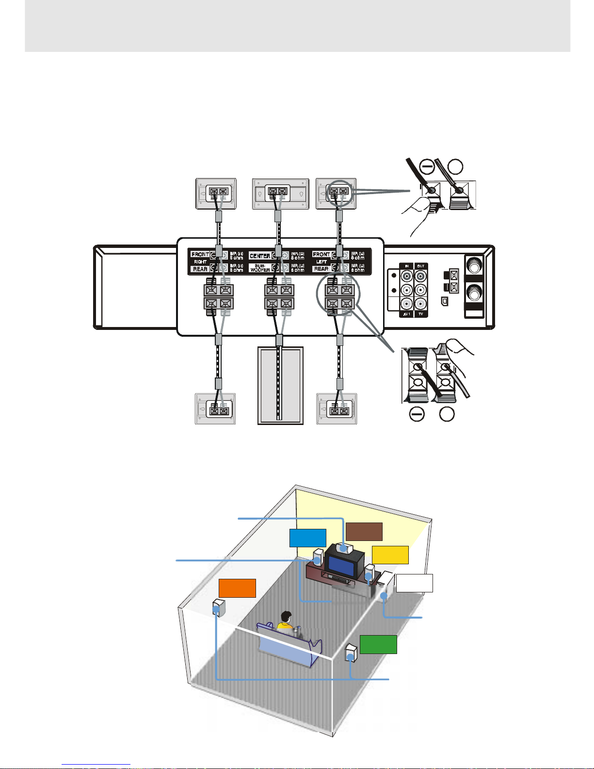
FRONT SPEAKERS
Place on both sides of the TV,
equal distances apart.
SUBWOOFER
Can be placed anywhere.
CENTER
Place on the top of
or below the TV.
SUB-
WOOFER
CENTER
FRONT
LEFT
FRONT
RIGHT
REAR
RIGHT
REAR
LEFT
3. Connecting the speakers & subwoofer
1. The speaker cords have been color-coded to simplify connection. Just plug the POSITIVE (+) and NEGATIVE (-)
ends of each speaker wire into the corresponding jacks on the rear of the Unit, matching the color tube on the end
of the speaker wire to the color-coded connector.
2. Connect each of the speaker wires to the satellite speakers. The front left/right and rear left/right speakers are all
the same. However, make sure you connect to the center speaker (color) to the one speaker which is slightly longer
than the rest.
4. Positioning the speakers and subwoofer
REAR SPEAKERS
Place right beside or slightly
behind your listening position,
and a little higher than your ears.
AM
LOOP
ANT.
FM A NT.
300
()
Ω
IN
OUT
VHF/UH F/
CATV
AC
R
L
AUDIO
VIDEO
+
+
SUBWOOFER
REAR (RIGHT) REAR (LEFT)
CENTERFRONT (RIGHT)
FRONT (LEFT)
- 17 -
Connections
(continued to next page)(continued to next page)
(continued to next page)(continued to next page)
(continued to next page)
Notes:
• If the external equipment is a television and this audio system is closed to it, you may experience interference if the
tuner function is selected while the television is working.
• When you have selected TUNER function, sound will ONLY come from the front left, right speakers and subwoofer.
• If you have a stereo VCR, make sure you set it in stereo mode.
• Due to copyright protection, DVD movies cannot be copied. If you copy a D VD mo vie onto a videotape , the resulting
copy will be unclear, with poor sound quality. This is NOT caused by a defective DVD system.
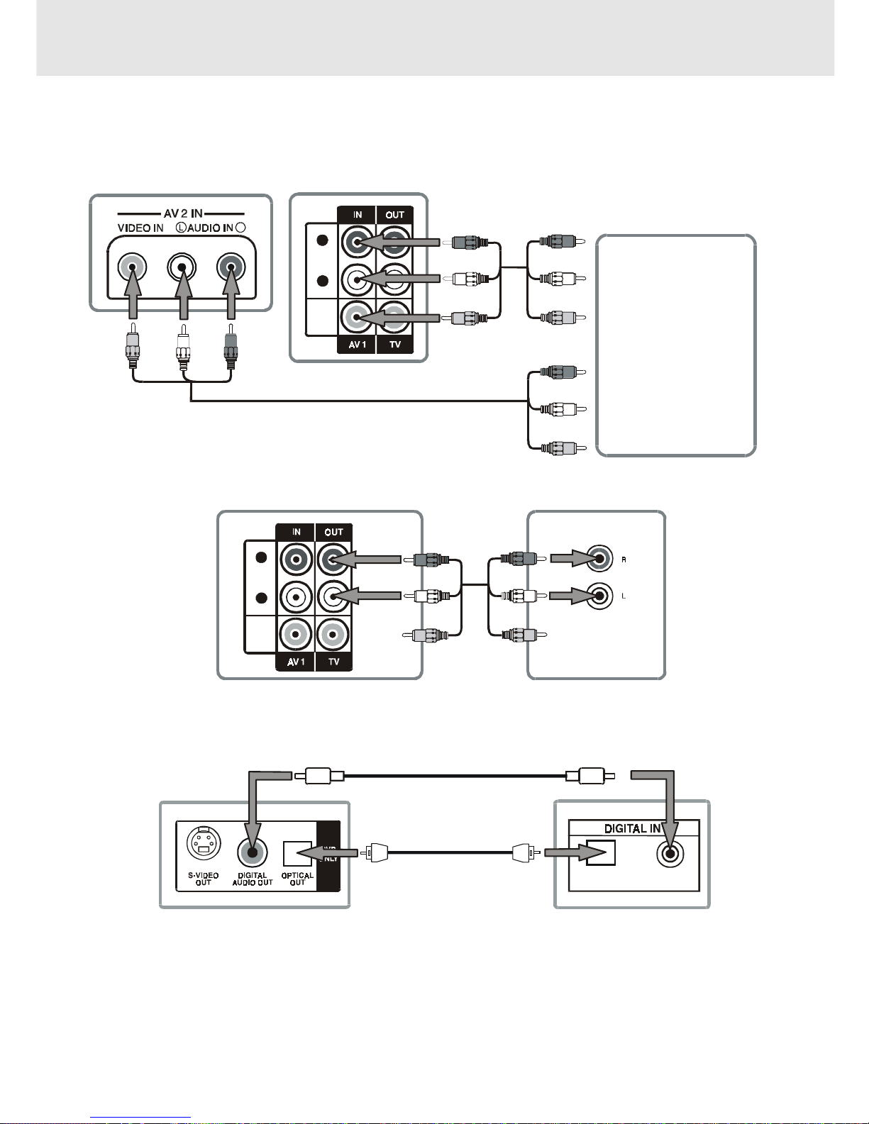
5. Connecting Other Equipment
You can connect other audio and/or video equipment to your unit in different w ays. The following illustrations give
a few examples of the connection possibilities.
Analogue connection
Digital connection
COAXIALOPTICAL
Camcorder
VCR
Sound
system
R
L
AUDIO
VIDEO
R
(Yellow)
(Yellow)
(Yellow)
(Yellow)
(Yellow) (Yellow)
(White)
(Red)
(White)
(Red)
(White)
(Red)
(White)
(Red)
(White)
(Red)
(White)
(Red)
(No need to connect)
(No need
to connect)
AUDIO IN
R
L
AUDIO
VIDEO
Optical digital cable (not supplied)
Coaxial digital cable (not supplied)
Rear of Unit
Audio equipment with
optical/coaxial digital input jack
Rear of Unit Amplifier of stereo system, etc.
Front of Unit
Rear of Unit
(VIDEO/AUDIO cable)
(VIDEO/AUDIO cable)
(VIDEO/AUDIO cable)
or (and)
- 18 -
Connections
Turning on the Unit and TV
1)Press the MAIN PO WER button to turn the Unit ON, or
2)Press the
/POWER button on the remote control while the Unit is in standby mode.
3)Turn on the TV by pressing its POWER button.
4)Select the channel on your TV corresponding to the VIDEO IN jack that the Unit is connected to. See TV User
guide for more information.
• If you have connected the Unit successfully, the DVD logo (start-up picture) will appear on your TV screen.
Power cord connection
• Make sure that all the components and speakers are connected correctly.
• To prevent electrical shock, match wide blade of plug to wide slot, fully insert.
• Be sure the AC power cord is disconnected and all functions are off before making connections.
• When you are not going to use the Unit for a long period of time, disconnect the power cord.
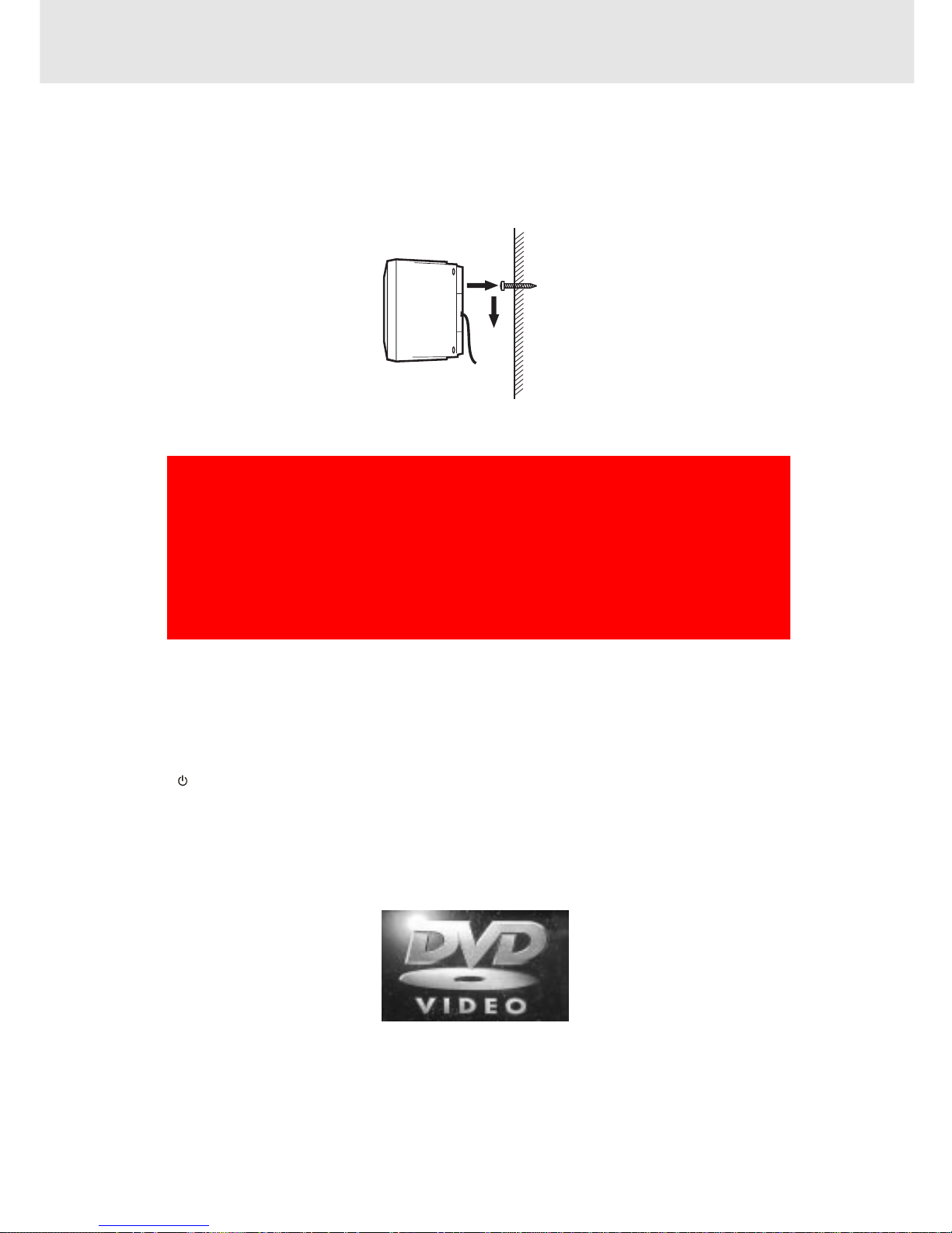
Mounting rear surround speakers
1) Mark the correct mounting position on the wall.
2) Insert a fixing screw(s) at the marked position on the wall.
3) Align the slot hole(s) of the speaker over the screw and pull the speaker downward until it is firmly hooked.
Need More Help?
DO NOT RETURN THIS TO THE STORE
Please call Customer Service at 1-800-252-6123
or visit online help at http://www.18002526123.com
- 19 -
To adjust the surround sound balance while Pro Logic decoding is in effect
Use the remote control to make the following changes to speaker balance:
Front speaker (left)
• Press the SOUND button repeatedly to display LEFT, then press the or CURSOR button to adjust the
sound level. It will show on the display of the Unit.
Front speaker (right)
• Press the SOUND button repeatedly to display RIGHT, then press the
or CURSOR button toadjust the
sound level. It will show on the display of the Unit.
Center speaker
• Press the SOUND button repeatedly to display CENTRE, then press the
or CURSOR button to adjust
the sound level. It will show on the display of the Unit.
Rear speaker (left)
• Press the SOUND button repeatedly to display REAR L, then press the or CURSOR button to adjust the
sound level. It will show on the display of the Unit.
Rear speaker (right)
• Press the SOUND button repeatedly to display REAR R, then press the
or CURSOR button to adjust the
sound level. It will show on the display of the Unit.
Subwoofer
• Press the SOUND button repeatedly to display WOOFER, then press the
or CURSOR button to adjust
the sound level. It will show on the display of the Unit.
Note :
• If you do not press any button within a few seconds, the display will return to normal.
To adjust the sound quality
Press the SOUND button repeatedly to select an equalization mode (BASS, MIDDLE, TREBLE). Press the
or CURSOR button to adjust the sound level.
BASS : the low range of sounds
MIDDLE : the mid range of sounds
TREBLE : the high range of sounds
Bass, middle and treble control the sound from the front left and right speakers.
Adjusting the Sound
(continued to next page)(continued to next page)
(continued to next page)(continued to next page)
(continued to next page)
Dolby Pro Logic is a sound system that was developed to get a better sense of presence from sources encoded with
Dolby Surround. The feeling of position has been improved by the addition of a separate center speaker channel. Look
for this logo on your DVD Unit.
Dolby Digital
Dolby Digital is a sound system developed by Dolby Laboratories Inc. that gives movie theatre ambience to audio output
when the Unit is connected to a Dolby Digital 5.1 channel processor or amplifier.
This Unit automatically recognizes DVDs that have been recorded with Dolby Digital.
Not all Dolby Digital sources are recorded with 6 channels.
Some sources marked Dolby Digital may be recorded in Dolby Surround, a 2 channel system. Look for this logo on your
DVD Unit.
Manufactured under license from Dolby Laboratories.
'Dolby' , 'Pro Logic' and the double-D symbol
are trademarks of Dolby Laboratories.
- 20 -
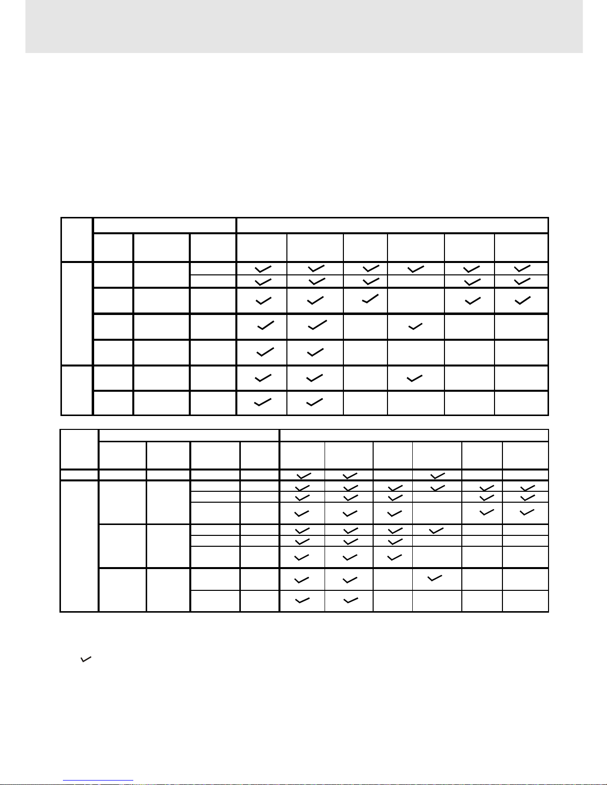
Adjusting the Sound
The following tables show which speakers are working in the various modes.
REMARKS:
1) Generally, only Front Left, Right speakers and Subwoofer are active at TUNER mode.
2) "
" The speakers is activated.
3) "
X " The speakers is not activated.
4) Always keep your VCR in stereo mode otherwise the speakers output status may be different to above listed table.
5) You can only set 5.1 CH, 2.1 CH when the disc is stopped.
6) In Subwoofer On mode, if speaker is set to "Large", then the output of subwoofer is low.
To select the listening channel
1. When the disc is stopped, you can press 5.1 CH and 2.1 CH buttons on the remote control to select different
speakers output status shown as below table.
2. You can active or off subwoofer output by setup menu.
Note:
The wording "2.1 CH" will be corresponded to the audio/sound output from Front Left and Front Right speaker
plus the Subwoofer.
5.1 CH /
2.1 CH
Subwoofer
L/R
Speaker
Front Left
Speaker
Front Right
Speaker
Center
Speaker
Subwoofer
Rear Left
Speaker
Rear Right
Speaker
Small
Lar
g
e X
Small /
DVD Lar
g
e
CD Small /
Lar
g
e
Small /
Lar
g
e
Small /
Lar
g
e
Small /
Lar
g
e
ON
Audio Settings Speakers Output Status
DISC
ON
MP3
OFF
5.1 CH
5.1 CH
2.1 CH
2.1 CH
N/A
N/A
OFF
ON
OFF
X
X
X
X
X
X
X
X
X
X
X
X
X
X
X
Output
Channel
3 Stereo /
Pro Logic
Subwoofer
L/R
Speaker
Front Left
Speaker
Front Right
Speaker
Center
Speaker
Subwoofer
Rear Left
Speaker
Rear Right
Speaker
TUNER
N/A N/A N/A N/A
XXX
ON Small
Pro ON Large
X
Logic Small /
Large
ON
Small
XX
ON
Large
XXX
Small /
Large
Small /
Large
Small /
Large
3 CH
2 CH
VCR /
AV_IN
Audio Settings
Sources
OFF
3 Stereo
OFF
OFF
ON
OFF
4 CH
XXXX
XXX
XXX
Speakers Output Status
X
 Loading...