

Page 1
Wireless B/W CameraWireless B/W Camera
Wireless B/W Camera
Wireless B/W CameraWireless B/W Camera
CCD CAMERA BASECCD CAMERA BASE
CCD CAMERA BASE
ANTENNAANTENNA
ANTENNA
ANTENNAANTENNA
1. Description1. Description
1. Description
1. Description1. Description
The VC-600 Camera is a wireless black-and-white
camera that is designed to be used in conjunction
with a VC-600 Wireless Receiver and VE-500
5-inch LCD Drop-Down Stereo TV or similar TV
with A/V inputs for baby monitoring, surveillance
around the home, etc.
2. Features2. Features
2. Features
2. Features2. Features
s IR LED’s for night operation.
s A choice of 4 channels for optimum reception.
s Sensitive, built-in microphone for enhanced
monitoring capability.
s 12V AC/DC adapter included.
s Camera automatically adjusts to allow
viewing brightly lit as well as dimly lit areas .
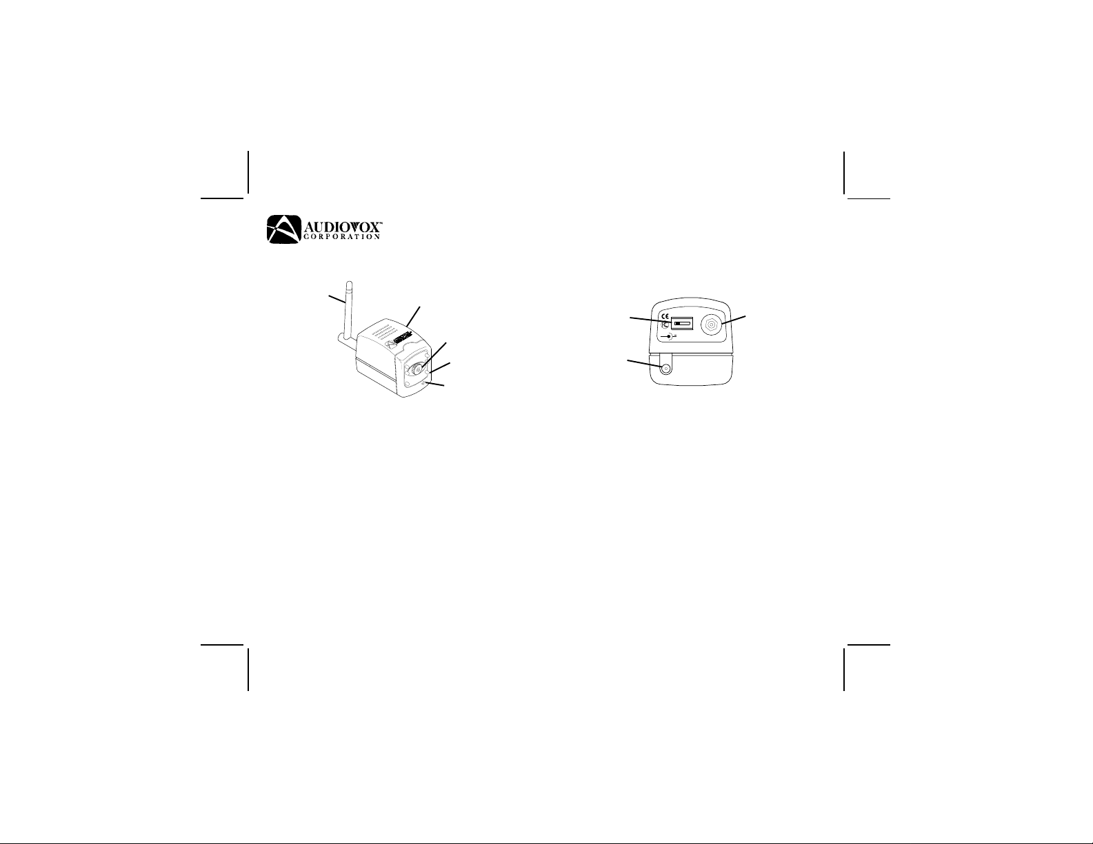
CCD CAMERA BASECCD CAMERA BASE
w/WIRELESS AV MODULE w/WIRELESS AV MODULE
w/WIRELESS AV MODULE
w/WIRELESS AV MODULE w/WIRELESS AV MODULE
1/3" CCD1/3" CCD
1/3" CCD
1/3" CCD1/3" CCD
IR LEDIR LED
IR LED
IR LEDIR LED
MICROPHONEMICROPHONE
MICROPHONE
MICROPHONEMICROPHONE
VV
V
VV
User’User’
User’
User’User’
CHANNELCHANNEL
CHANNEL
CHANNELCHANNEL
SELECTIONSELECTION
SELECTION
SELECTIONSELECTION
POWERPOWER
POWER
POWERPOWER
JACKJACK
JACK
JACKJACK
3. Included In This Kit3. Included In This Kit
3. Included In This Kit
3. Included In This Kit3. Included In This Kit
s VC-600 camera
s Antenna
s User’s manual
s Two mounting brackets:
- wall mount with 3 screws
- table top mount
s 12V AC/DC adapter (500 mA.)
4. Tools Required4. Tools Required
4. Tools Required
4. Tools Required4. Tools Required
s #1 Phillips-head screwdriver
5. Installation Precautions5. Installation Precautions
5. Installation Precautions
5. Installation Precautions5. Installation Precautions
s Avoid exposure to direct sunlight.
s Be careful not to spill any wate r on the unit.
s Do not shake or vibrate the unit.
s Use a soft cloth moistened with warm
11
1
11
1 2 3 41 2 3 4
1 2 3 4
1 2 3 41 2 3 4
+
DC 12VDC 12V
DC 12V
DC 12VDC 12V
s Mans Man
s Man
s Mans Man
ANTANT
ANT
ANTANT
ANTENNAANTENNA
ANTENNA
ANTENNAANTENNA
CONNECTORCONNECTOR
CONNECTOR
CONNECTORCONNECTOR
C-600C-600
C-600
C-600C-600
ualual
ual
ualual
Released 12-14-99.
128-5680128-5680
128-5680
128-5680128-5680
1 of 41 of 4
1 of 4
1 of 41 of 4
Page 2
water to wipe off any dust, if necessary.
s Do not touch the CCD sensor. If necessary, use
a soft, lint-free cloth moistened with alcohol
to clean the CCD sensor.
s If the camera does not operate properly,
unplug the unit and contact your local
dealer.
6. Installation6. Installation
6. Installation
6. Installation6. Installation
s Select base to be used.
s Screw the camera to the base. If using the
wall mount, screw the base to the wall before
attaching camera.
8 .8 .
8 .
8 .8 .
SS
S
SS
pp
p
pp
ee
e
ee
cc
c
cc
ii
i
ii
ff
f
ff
ii
i
ii
cc
c
cc
aa
a
aa
tt
t
tt
ii
i
ii
oo
o
oo
nn
n
nn
ss
s
ss
CHANNELCHANNEL
CHANNEL
CHANNELCHANNEL
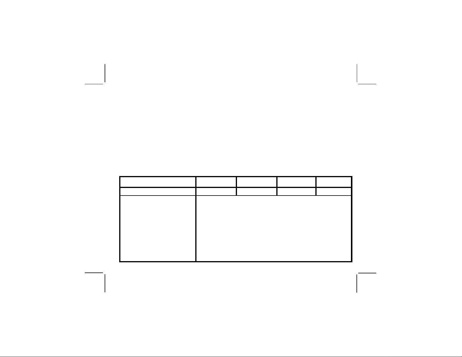
FREQUENCY 2413 MHz 2432 MHz 2451MHz 2470 MHz
OUTPUT POWER 10 mW
OUTPUT IMPEDANCE 50 ohms typical
POWER 12 VDC supplied by AC/DC adapter
CURRENT 260 mA
VIDEO OUTPUT 1Vp-p composite video (75 ohms)
AUDIO OUTPUT 2Vp-p max
DIMENSIONS
OPERATING TEMPERATURE -10° C to +50° C
WEIGHT 115 grams
CH1CH1
CH1
CH1CH1
L:L:
L: 77mm
L:L:
s Carefully screw the antenna to the camera.
s Plug the AC/DC adapter into the camera Power
Jack and then into the wall.
s Set channel select switch to the corresponding
channel of the receiver.
s Adjust the camera for best viewing angle.
7. Channel Selection7. Channel Selection
7. Channel Selection
7. Channel Selection7. Channel Selection
After connecting and turning on the equipment,
select the channel that gives the best reception and
least interference. The channel number must match
the channel number of the receiver. The antenna
is normally positioned vertically but its angle m a y
be changed to obtain the best reception.
H:H:
H: 56mm
H:H:
CH2CH2
CH2
CH2CH2
D:D:
D: 56mm
D:D:
CH3CH3
CH3
CH3CH3
CH4CH4
CH4
CH4CH4
22
2
22
128-5680128-5680
128-5680
128-5680128-5680
2 of 42 of 4
2 of 4
2 of 42 of 4
Page 3

Video+AudioWireless ReceiverVideo+AudioWireless Receiver
Video+AudioWireless Receiver
Video+AudioWireless ReceiverVideo+AudioWireless Receiver
VIDEOVIDEO
VIDEO
VIDEOVIDEO
OUTOUT
OUT
OUTOUT
DC 12VDC 12V
DC 12V
DC 12VDC 12V
CHANNELCHANNEL
CHANNEL
CHANNELCHANNEL
SELECTIONSELECTION
SELECTION
SELECTIONSELECTION
AUDIOAUDIO
AUDIO
AUDIOAUDIO
OUTOUT
OUT
OUTOUT
ANTENNA CONNECTORANTENNA CONNECTOR
ANTENNA CONNECTOR
ANTENNA CONNECTORANTENNA CONNECTOR
1. Description1. Description
1. Description
1. Description1. Description
The VC-600 Receiver is a wireless receiver that is
designed to be used in conjunction with a VC-600
Camera and VE-500 5-inch LCD Drop-Down
Stereo TV or similar TV with A/V inputs for baby
monitoring, surveillance around the home, etc.
2. Features2. Features
2. Features
2. Features2. Features
· A choice of 4 channels for optimum reception.
· 12V AC/DC adapter included.
3. Included In This Kit3. Included In This Kit
3. Included In This Kit
3. Included In This Kit3. Included In This Kit
· VC-600 Receiver
· Antenna
· User’s manual
· 3.5x20 screws (4)
· Plastic conical anchors (4)
· 12V AC/DC adapter (500 mA.)
· A/V cable
· White power cable for powering the unit from
a VE-500 5-inch LCD Drop-Down Stereo TV
4. Tools Required4. Tools Required
4. Tools Required
4. Tools Required4. Tools Required
· #1 Phillips-head screwdriver
5. Installation Precautions5. Installation Precautions
5. Installation Precautions
5. Installation Precautions5. Installation Precautions
· Be careful not to spill any water on the receiver.
· Use a soft cloth moistened with warm water
to wipe off any dust, if necessary.
· Do not shake or vibrate the unit.
· If the receiver does not operate properly,
unplug the unit and contact your local dealer.
6. Installation6. Installation
6. Installation
6. Installation6. Installation
· The receiver may be placed on a flat surface
or it may be permanently mounted by using
the four supplied screws and plastic conical
anchors.
· Carefully screw the antenna to the receiver.
33
3
33
128-5680128-5680
128-5680
128-5680128-5680
3 of 43 of 4
3 of 4
3 of 43 of 4
Page 4

· Find a suitable location for the receiver.
· Plug the RCA cable into the A/V outputs
(yellow to video out and white to audio out).
· Plug the other end of the RCA cable into the
A/V inputs of the TV monitor to be used.
· If using this receiver with any Audiovox
VE-XXX series product, plug the white dc
power cable into the receiver and plug the other
end with the center pin plug into the VE-XXX.
· Use AC-DC adapter if not connecting to
8.8.
8.
8.8.
SS
S
SS
pp
p
pp
ee
e
ee
FREQUENCY 2413 MHz 2432 MHz 2451MHz 2470 MHz
cc
c
cc
IMPEDANCE 50 ohms typical
ii
i
ii
ff
f
ff
POWER 12 VDC supplied by AC/DC adapter
ii
i
ii
CURRENT 280 mA
cc
c
cc
VIDEO OUTPUT 1Vp-p composite video (75 ohms)
aa
a
aa
tt
t
tt
AUDIO OUTPUT 2Vp-p max
ii
i
ii
DIMENSIONS
oo
o
oo
nn
n
nn
OPERATING TEMPERATURE -10° C to +50° C
ss
s
ss
NOTICE: Due to the nature of RF (Radio Frequency) signals, interference
other deother de
other de
other deother de
porpor
por
porpor
MoMo
ving the camera and/or receiver farving the camera and/or receiver far
Mo
ving the camera and/or receiver far
MoMo
ving the camera and/or receiver farving the camera and/or receiver far
interfinterf
interf
interfinterf
CHANNELCHANNEL
CHANNEL
CHANNELCHANNEL
vices that gvices that g
vices that g
vices that gvices that g
tabtab
le radio transceiverle radio transceiver
tab
le radio transceiver
tabtab
le radio transceiverle radio transceiver
erenceerence
..
erence
erenceerence
Occasional interf Occasional interf
.
Occasional interf
..
Occasional interf Occasional interf
CH1CH1
CH1
CH1CH1
L: L:
L: 115mm
L: L:
enerate radio frequencies (sucenerate radio frequencies (suc
enerate radio frequencies (suc
enerate radio frequencies (sucenerate radio frequencies (suc
s) when thes) when the
s) when the
s) when thes) when the
y are operated in the vicinity of this camera and receivery are operated in the vicinity of this camera and receiver
y are operated in the vicinity of this camera and receiver
y are operated in the vicinity of this camera and receivery are operated in the vicinity of this camera and receiver
ther ather a
wawa
ther a
wa
ther ather a
erence is normal and does not indicate a deference is normal and does not indicate a def
erence is normal and does not indicate a def
erence is normal and does not indicate a deference is normal and does not indicate a def
wawa
VE-XXX in which case the white DC
Power cable is not used.
7. Channel Selection7. Channel Selection
7. Channel Selection
7. Channel Selection7. Channel Selection
After connecting and turning on the equipment,
select the channel that gives the best reception
and least interference. The channel number
must match the channel number of the camera.
The antenna is normally positioned vertically
but its position may be changed to obtain the
best reception.
CH2CH2
CH2
CH2CH2
H:H:
H: 23mm
H:H:
y f ry f r
y f r
y f ry f r
D:D:
D: 80mm
D:D:
h as micrh as micr
h as micr
h as micrh as micr
oo
wawa
o
wa
oo
wawa
om these types of deom these types of de
om these types of de
om these types of deom these types of de
ve ove o
ve o
ve ove o
CH3CH3
CH3
CH3CH3
vens,vens,
vens,
vens,vens,
mama
y occur fry occur fr
ma
y occur fr
mama
cor cor
cor
cor cor
y occur fry occur fr
dless phones anddless phones and
dless phones and
dless phones anddless phones and
vices mavices ma
vices ma
vices mavices ma
ective prective pr
ective pr
ective prective pr
CH4CH4
CH4
CH4CH4
y y
eliminateeliminate
y
eliminate
y y
eliminateeliminate
oduct.oduct.
oduct.
oduct.oduct.
omom
om
omom
..
.
..
© 2000 Audiovox Corporation, Hauppauge, NY 11788 128-5680
128-5680128-5680
128-5680
128-5680128-5680
4 of 44 of 4
4 of 4
4 of 44 of 4
 Loading...