

Page 1
INSTALLATION PROCEDURES
~NG CABLE (continued) I
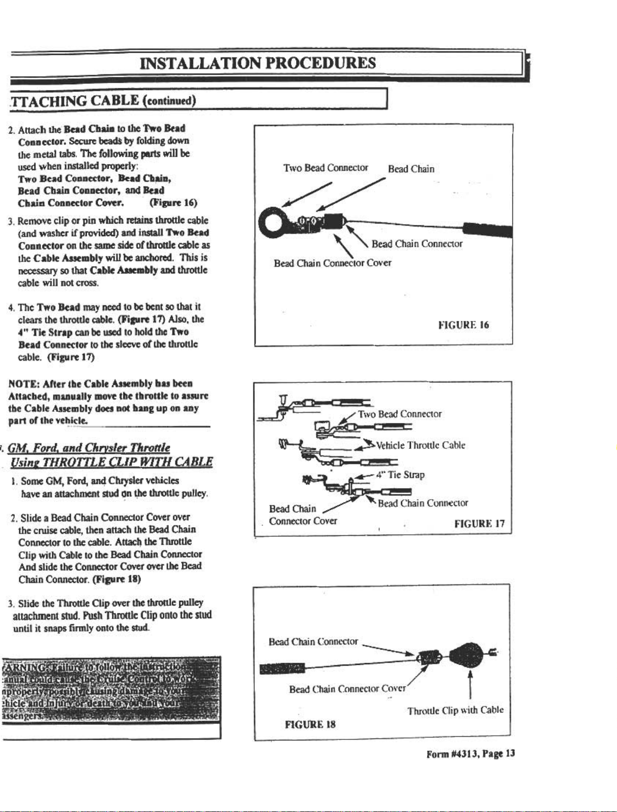
2. Attach the Bead CbaiD to the Two Bead
Connector; Secure beadS by folding down
the metal tabs. The following parts will be
used when installed properly:
Two Bead ConDector, Bead Cb~D,
Bead CbaiD CoDnector, and Bead
CbaiD CoDDector Cover. (Figure 16)
3. Remove clip or pin which retains throttle cable
(and washer if provided) and install Two Bead
Connector on the same side of throttle cable as
the Cable Assembly will be anchored. This is
necessary so that Cable Asaeinbly and throttle
cable will not cross.
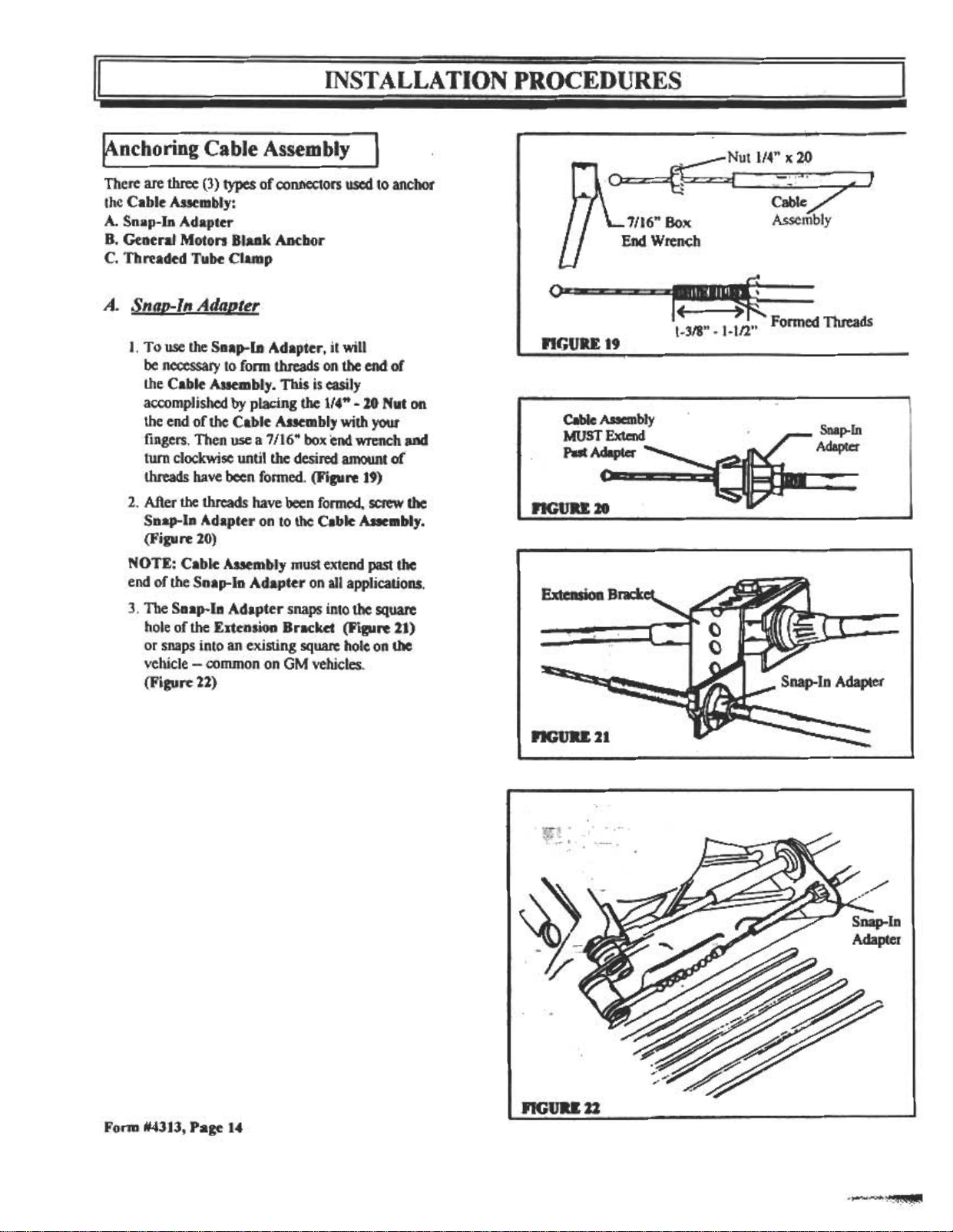
4. The Two Bead may need to be bent so that it
clears the throttle cable. (Figure 17) Also, the
4" Tie Strap can be used to hold the Two
Bead Connector to the sleeve of the throttle
cable. (Figure 17)
NOTE: After the Cable Assembly has been
Attached, manually move the throttle to assure
the Cable Assembly does not hang up on any
part of the vehi~le.
1, GM. Ford. and Chrvsler Throttle
Usin~THRQ1TLE CLIP WlTHCABLE
I. Some OM, Ford. and Cbrysler vehicles
have an attachment stud qn ~e throttle pulley .
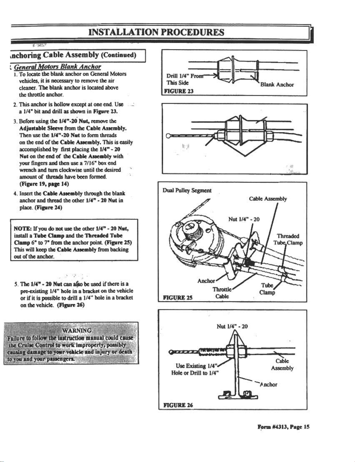
2. Slide a Bead Chain Connector Cover over
the cruise cable, then attach the Bead Chain
Connector to the cable. Attac~ the Throttle
Clip with Cable to the Bead Chain Connector
And slide the Connector Cover over the Bead
Chain Connector. (Figure 18)
3. Slide the Throttle Clip over the throttle pulley
attachment stud. Push Throttle Clip onto the stud
until it snaps firmly onto the Stud.
FIGURE 18
Throttle Clip with C-able
Form #4313, Page 13
Page 2
~nchoring Cable Assembly I
There are three (3) types of connectors used to anchor
the Cable Assembly:
A. Snap-ln Adapter
B. General Motors Blank Anchor
C. Threaded Tube Clamp
~
114" x 29
Cable
---7116" Box
End Wrench
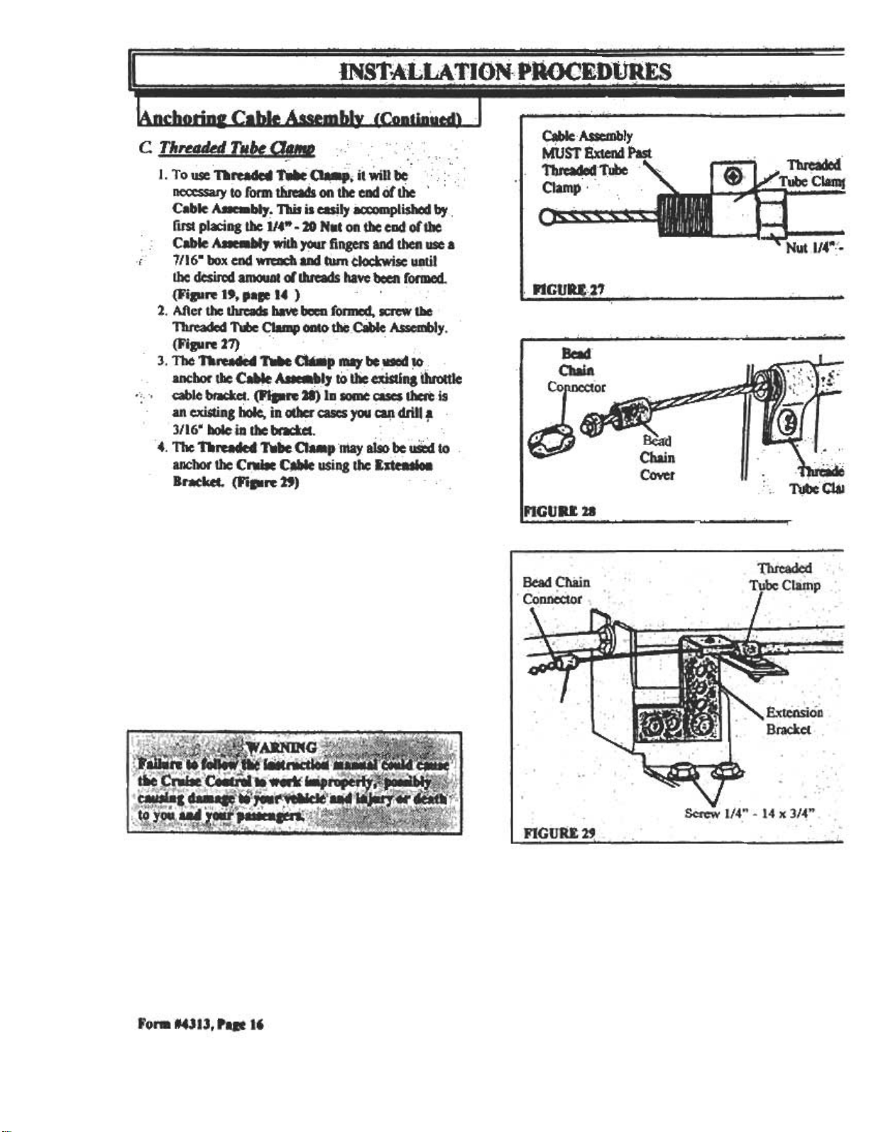
A. Snap-ln Adapter
I. To use the Snap-ln Adapter, it will
be necessary to fonn threads on the end of
the Cable Assembly. This is easily
accomplished by placing the 114" -10 Nut on
the end of the Cable Assembly with your
fingers. Then use a 7116" box end wrench and
turn clockwise until the desired amount of
threads have been Conned. (Figure 19)
2. After the threads have been formed, screw the
Snap-ln Adapter on to the Cable Assembly.
(Figure 20)
NOTE: Cable Assembly must extend past the
end of the Snap-In Adapter on all applications.
3. The Snap-ln Adapter snaps into the square
hole of the Enension Bracket (Figure 11)
or snaps into an existing square hole on the
vehicle -common on GM vehicles.
(Figure 21)
OZ~~~~:=
nGUU 19
Cable Assembly
MUST Extend
Put Adapter
nGUH 20
1-3/8" -1-1/2" Formed Threads
Snap-In
Adapter
FonD #4313, Page 14
:~."'""~
Page 3
INSTALLATION PROCEDURES
, ,
lDchoring Cable Assembly (Continued)
t General Motors Blank Anchor
--, .
1. To locate the blank anchor on General Motors
vehicl~, jljs necessary to remove the air
cleaner. The blank anchor is located above
the throttle anchor .
2. This anchor is hollow except at one end. Use
a 114" bit and drill as shown in Figure 23.
3. Before using the 114"-20 Nut, remove the
Adjustable Sleeve from the Cable A3sembly.
Then use the 114"-20 Nut to fonD threads
on the end of the Cable Assembly. This is easily
accomplished by first placing the 114" -20
Nut on the end of the Cable Assembly with
your fingers and then use a 7116" box end
wrench and tucfn clockwise until the desired ,
amount of threads have been formed.
(Figure 19, pa&e 14)
4. Insert the Cable Assembly through the blank
anchor and thread the other 114" -20 Nut in
place. (Figure 2.4)
I Drill 114"
This Side
FIGURE 23
Anchor
, -;, ,
5. The 114" -20 Nut cali .be used if there is a
pre-existing 114" hole in a bracket on the vehicle
or if it islX>SSible to drill a 114" hole in a bracket
on the vehicle. (FIgure 26)
I
Form 1#4313, Page 15
i
Page 4
.IN1 a'.' :.,;.-,. ,:.: ~
16~ p.n.n'.'~cb. m
ES" ~ I HbLiR'A Ul~, :~~U~R .
c T"rellMdT,,~a.. " ,:. ,
I. To ~ TbreadCd ~~P. it Win~ c: .
necessary to form threads on the end of' the .
-.,
" "
Cable AJIeIDbly.1bis is casJly accompliShed ~ .
first pl'M;ing the 1/4" -20 NMt on the end of1he
.: Cable AJIe8b1y with ~ fingers and then use a
i 7/16- box end wre..:h -turn clockwi~ ~til
the des~ aII1CMIDt ~ threads ~ve been formed.
(Fi.re 19, pa. 14 )
2. After the threads have been fonl1ed, a;rew the
Threaded ~ Clamp onto ~ c8b1e ~Iy.
(Ji'igure 27) .
.3. The r.rea.. T*aa8p -be.~ ~
.ancborthe C~ ~b'~ to ~WSUn.t1uottle
..:' ., cable ~. ~re 28) lD~ ~lhe.eis
an existing ~ in *r cases you ~dril' ~
3116- iW)Ie in the br'actel .
" ,:'
4. The nreaded T.bc a..pniay .be ua to
anchOr theCNile C.able using tIle: r.stt8si08
Bratket. (Fi..re 29) .
~Ie Assembly
MUST~ndPast
ThrCaded-rUbC
Clamp'"
nCURI.,21
Bead
Chain
nGtJRI. 18
Cflain
COvet
-.-"'
I ~.
4\.
~
/1iibe C..
~
~
.; .~ Clai
I ff:
.'..'
~
Fora 14313, Pa&e 16
Page 5

~arness Assembly I
Push Rubber Cover Grommet securely into place on
the cover of the Actuator Assembly. (Figure 30)
Straighten the Harness Assembly and find the 4 pin
mating connectors. Separate the 4 pin connectors. A
small screw driver may be needed.
Bamess Assembly needs a 314" hole to pass through
bulkhead. You may find one nearby such as the
speedometer cable hole or a small one you can file
larger. If you find the right size hole in the right
place, remove ru~r grommet. If not, drill, saw, or
punch a 314" hole in bulkhead. A hole a couple of
inches to the left or: slightly higher than the steering
column is usually a ~00d place. (FiEUre 31)
OTE: Check inside before drilling, sawing, or
linEso you don't dama!e anything.
From engine side, pass four pin connector and
VIOLET wire through hole. If you did not hook up
the BLUE TACH wire and GRAY VSS wire under
the hOOd, pass them through to the inside also.
Reattach 4 pin mating connectors and make
necessary wire connections. (See page 18)
,
~~
~
eat hole in bulkhead with Sealing Putty as shown
1 Figure 32.
)
FonD *4313, ..17
Page 6

" ,. ..\ f
ICruise Control Switch Installation I ,.' """;,,,!
'i'
If your Cruise Control switch is the type which clamps on the turn signal lever, req~ cutting the turn signalJever, or is
mounted on the instrument panel, follow instructions pack~~with it If you have a switch which replaces the cpntplete original
equipment turn signal lever, remove the existing lever and install the Cruise Control switch and lever assembly as instructed in
the vehicle shop servire manual.
I WIRING A Tf ACHMENTS TO VEH "~ ' ' c";
To find a place to get electrical power you will need to "ground" one lead of your test light or volt-ohm -.Find el~cal
..
ground by turning on the ignition switch and touching one lead to a 11« fused tenninal at fuse pan~l; toucbc~r lead to
unpainted metal part of vehicle. The metal you touch, if it makes (X)ntinuity , is ~d. Bracket for parking brake lever is usually
a good ground. Turn ignition switch off.
NOTE: Some fuse panels are behind shields which must be removed first. On other vehicles the screw that mounts the panel
must be removed to get to the fuses.
~.: ..
WIRE
I COLOR
~
BLACK
BROWN
RED
-~
VIOLET
GROUND
-
ACCESSORY POWER
CONSTANT POWER
GROUND
FUNCTION
-
~
WCATION
Vehicle puMIlM>int which is a clean ~nted metal
surface ,
NOTE: 00 NOr USE mE ENGINE AS A
GROUNDING POINT. 00 Nor CONNECf TO mE
EXTENSION BRACKET
F~ panel: fuse that bas + 12 volts when key is ON and
O wits when key is OFF or in the ST ART (CRANK)
position.
Hot side of brake switch -+ 12 volts
~ ~-
Cold side of brake switch -O resistance when brake is not
-
I p~-~l,~ wits or open resistance when brake is
BLUE
GRAY.
-consult Vehicle Shop Manual
TACHOMETER
.-,
VEHICLE SPEED SENSOR
See v~ TdlliCGIl,,/ormlltioll G,,- (FOnD #2482)
! or
consult Vehicle Shop Manual
See V~ TdlliCGIl"/omultio,, G"ide (FOnD #2482)
or
--
Form #4313, Page 18
Page 7

SELF DIAGNOSTICS PROCEDURES
, :~:~:~,';
otering'Diagnostics Mode:
I. Turn the Cnlile Control Switch to the OFF position
2. Turn the ignition switch to the OFF position
3. Press aDd hold the USUME/ACCEL slide switch wbile you turn the ignition switch to the ON position without
.-.rtIIIg tie -g;,.~ Now release the USUMVACCEL slide ~tch. (If you are using a 250-3592, 250-3593,
250-3742 or 250-3743 Cnlile Control S~ bIrD tbc ignition switch to the ON position wit1loll' starting the
-g;,.e, hold the USUMFJACCEL button... wbileyCMl turn the Cnlile Control Switch to the ON position.)
4. The Diagnostics LED should be off at this ~
!ltiag the Cnlile Control Switch, Brake Swid Wlri8c. ud Vehkie Speed SeDsor (VSS) Signal:
-If NOT- Pre8881Mi reIc8Ie SET/COAST button.
~ = t,.. =t=~: :i;.=;... =::;A I LED ~ IiIbt e8:h tiDIe 00tt00 is
~:r ; to entering ~cs mode I prc8Ied IIMI u when it is released. -IF NOT-
d tryasain jp ~ --I Check ~s ; en~ di;ostic mode and I
I ;~in-l'~ ~ ~'6 ~"6'.u~ .~ I
teck Swit£h .7:
OFF: N~ly OPEN switch
ON: NOmIaIly CLOSED switch
Bet iJIaXTectly. = andre-.enter I
~~. I
I
~ power to Actuator Assembly. if
me of the diagnostic commands are
nctionin~
beck Cruise Control Switch
i -IF' NOT-
~ ~ to en~ diagnostic ~ I
;d;y "~ ~ ~ aue ..."6' ~ I
IXDe vehicles need ; be pusbed D1<X'e than I
; (j)f;-; ~ --1'-- ..~~ w-.I
~ fo Ibc V~cle S.-I- ;.1
I I -
Press and Jel~ the
RESUMFJACCEL swit(:h. LED should
ligbt each time the switch is pressed
and to out when itis Jeleased.
IPYIS
D'YIS
-f
Test VEIDCLE SPEFD SENSOR
(VSS):
I A seccxtd perD1 is ~ to check
visual status of the LED. Push car at
least tiu'ec (3) feet f<XWlJd oc
b8CkW8I'd. LEDsbould Oesb at least
once.
OR
Check power to Actu~tor Assembly if none
of dIe diagnostic commands are fw1ctioning
I Check Cruise Control Switch I
IF NOT-
I Check steps to enterin~ diagnostic mode and I
I ~~ht-1'- e -.-e-.~:..~ ...:~ ~.~ I
I Check power to Red = I
Check power to Actuator Assembly, if none
of the diagnostic conunands are functioning
I Check Brake Switch ;d wiring to Brake I
I s~h~ u~.~.. ~ '6 .., ~ I
IF NOT-
I Check ,steps to enterin~ diagnostic mode and I
I ;;;~~in~l'~ .v W&.~& ~&e -.'"e'&V~~W U&~ -.-I
'., .
,
he ccxmectioo JX»int fM dac Vehicle Speed
«*X'illM)t~
,;"
T..AUXDJARY SPEED ~~Jt
lSignal Generat«):
A SCCOIMI perD1 is ~ to ch~k
visual status of die LED. One drive
wheel needs to be jKked-up, take care
10 ~ a suwcxt sta f« ~. Spin
wheel by ham.. fast u )'OU can. LED
I should flash.
I Check Programming Switch N 10, it should be I
I OFf I
I If switch is ON reset to OFF and re-enter I
I diagnostic mode I
You must spin the wheel at least 3 MPH or
faster in order to test an auxiliary signal
generator
Form #4313, Page 19
Page 8

If all 01 die previous functions are correct, check the T ACB Signal
I. Turn the Cnaile Coatrol Switch to the OFF position
2. Turn the ignition switch to the OFF position
3. Press and hold the RESUME/ACCEL slide switch while you turn the ignition switch to the ON position and start
lie .,.g;,.e. Now release the RESUME/ACCEL slide switch. (If you are using a 250-3592 or 250-3593 dash mount
Cnile Coatrol Switch, turn the ignition switch to the ON position and stl111 the engine, hold the RESUME/ACCE
.button 00wn while you turn the Cruise Control Switch to the ON position.)
4. The Diagnostics LED should be flashing. Rev the engine, the LED should flash faster at higher RPM's. If not:
.Check steps to entering diagnostic mode and tJy again
.Connection to T ACH Signal source is bad ~ 0-
.T ACH Signal connection point is not correct
CONTROL SWITCH TESTS
,. .* tat:
I. Unplug the S-pin connector from the Actuator Assembly.
2. Ground the test light lead and verify that the test light works by proving with a known po~er source.
TES:It'HART A (FOR ~LOSED CIRCUIT ~QNTROL sWITcm
IGNITION
SWRCB
; POSmoNS
j orr
I
, orr
OFr
On'
ON
CaANKor
-
CONTROL
SWITCH
POSITIONS
OFF
-
ON
ON
press and bold
SET/COAST
ON
press and bold
RESUMEI ACCEL
ON
-
ON
RED
OFF
~
ON
ON
ON
ON
ON
DARK
GREEN
OFF
ON
OFF
ON
ON
-
ON
YELLOW
OFF
OFF
ON
ON
2!!
OFF
BROWN
OFF
~
IGNmON
SWITCH
-POS~NS I
: iiij
OFf
orr
ON
C84NK or
,- NJI.1, ..ce 10
TEST CHART .
CONTROL
i POSITIONS
SWITCH
OFF
~
ON
press and bold
SET/COAST
ON
preu and bold
RF.SUME/ACCEL
ON
ON
(FOR OPEN CIRCUIT-~ONTROL swITcm
RED
-~
DARK
GREEN
OFF
-
-~N
~
ON
ON
ON
~c-- ON
OFF
OFF
"=-.
OFF ON
OFF
OFF
YELLOW
OFF
-
OFF
OFF OFF
OFF
-
OFF
BRO~
OFF
ON
Page 9

:" ~
-In
"~~
~l
~
¥
.~
211:
~~
~
~
~
0
.;I
c
)ooZ
<0
~~
.
~
":,;jE9~~ :
.~
y
" ,<2 Q -~
0
~
.
cO
~
1&1
..
~
,i
~
Go
Q
,
z c>(J,VJ~' -
~ rc,.r: li
0
~~
~8
~«
~o
~
,..
~
o~
IJftO
0 ...
,-
.I~
0.
...;J
u.
u.
~
z
0
-'
w
Q
Q
c
.
w
2
~
~
w
"
~O
<~
I~
00
~O
Fonn t431J, Page 21
~
~
Page 10

In the event that you need technical assistance with trouble shooting, please have the following
infonnation ready when calling our TechhicalService Department 910-277-1828. This inThfrnation
is important for a proper and speedy diagn~sis of the problems encountered.
Model Number of Cruise Control System pnnted on box and manufacturers code printedoii;the
Actuator Assembly
Vehicle Make Model and Year:
Engine and Transmission:
Ensure that the Brake Switch wiring connections are correct. "
Red wire of WirinrHarness Assembly is connected to "HOT SID~11(co.or):
Violet wire of Wirinl Harness Assembly is connected to "COLD StD~" (cblor):
Ensure that the Brown wire is connected to an "i&nition power sou'rce"
Speed Signal Source:
VSS (Vehicle Speed Signal): Gray wire connection point and wire color:
Alternative Speed Si&Dal Source (part *)" , :' ; I' r,
Tachometer Silnal: Blue wire connection point and color
Actuator Assembly prolramming switch settinls:
1 2 ,;3, 4
I "
"'
5r
..
6
8 9
7
10
ON
OFF
List the parts used for the throttle connection and cable anchoring. Refer to the Parts List all
Parts Diagram on Pages 4-5.
Form #4313, Pa&e 1.2
Page 11

36 M O NTH/36,000 MILE LIMITED W ARRANTY
AUDIOVOX CORPORATION (The Company) warrants to the original retail purchaser of this Cruise Product that should this
product or any part thereof, under normal use and conditiOns; be proven defective material or workmanship within 36 months
or 36,000 miles of the original purchase, such defect(s) will be repaired or replaced (at the Comoanv's ootion) without charge
for the parts.
To obtain repair or replacement within the ter8 fl ~ WarrMty, tk product is to be delivered with proof of warranty
coverage (e.g. dated bill of sale), specirl(.ati08 fl dded(1), sportatioD prepaid, to an approved warranty station or
the Company at the addreu shown below.
This Warranty does not cover costs incurred for removal or reinstallation of the prOOuct, or damage to vehicle electrical systems.
This Warranty does not apply to any prOOuctor part t1tCraJfwbich in the opinion of the Company has been damaged through
alteration, improper installation. mishandling. Ini-. MaIa:t. or I(x:ident.
This Warranty is in lieu of all other express warrIDtieI..li8iliIics. ANY IMPLIED WARRANTIES, INCLUDING ANY
IMPLIED W ARRANTY OF MERCHANT ABn..rrY ,SHAu. BE LIMrrED TO mE DURA TION OF TIllS WRITI'EN
WARRANTY. ANY AcnON FOR BREACH OF ANY W ARJANrY HERE UNDER INCLUDING ANY IMPLIED
W ARRANTY OF MERCHANT ABn.ITY MUST BE BROUGIrr WJ11DN A PERIOD OF 18 MONmS FROM DATE
OF ORIGINAL PURCHASE. IN NO CASE SHALL 11IE COMPANY BE LIABLE FOR ANY CONSEQUENTIAL OR
INCmENT AL DAMAGES FOR BREACH OF nus OR ANY' OTHER. w ARJANrY , EXPRESS OR IMPLIED,
WHATSOEVER No person or representative isa8i8laizccl to assume for the Company any liability other than expressed
herein in connection with the sale of this prOOuct.
THE EXTENT OF THE COMP ANY'S LIABUJTY UNDEJl nus W ARJANrY IS LIMITED TO THE REPAIR OR
REPLACEMENT PROvmED ABOVE AND. IN NO EVENT, S:HALL mE COMPANY'S LIABn.ITY EXCEED THE
PURCHASE PRICE PAID BY THE PURCHASER FOR "nIE PRODUCT.
Some states do not allow limitations on how long ...implied warranty lasts or the exclusion or limitation of incidental or
consequential damage so the above limitations or extlusions may not apply to you. This Warranty gives you specific legal
rights and you may also have other rights which vary from state to state.
,. ,0
INEASTERNU.S.A.: AUDIOVOXCORPORAnON.60ARKAY~HAUPPAUGE.NEWYORK 11788 Phone (516)231-6051
IN WESTERN U.S.A.: AUDIOVOX WESTCORPORAnON,16808MARQUARDTAVE. CERRffOS, CA 90701 Phone (213) 926-7758
OWNER'SW ARRANTY RECORD
(To be completed by selling dealer and retained by customer)
Customer's Name
Address
Dealer Name
Dealer Address
City
Date Purchased
Date Installed
Form #4313, Pa~e 23
 Loading...