

Page 1
TV4
OWNER’S MANUAL
TV4
Indoor Television Antenna
Page 2

TV4
About Your TERK TV4
Thank you for choosing the TERK TV4. TERK antennas are
designed to help deliver sharp, clear video reception. At
TERK, our engineering department is dedicated to
designing antennas that enhance both the latest
technology and the aesthetics of any viewing environment.
The TV4 installs in minutes, is easy to use and simple to
adjust. Before using your antenna, please remove all parts
from the box and read the owner’s manual carefully.
The TV4’s unique and patented “Complentary Symmetry”
technology utilizes two tuned elements, which have a large
capacity for receiving VHF and UHF signals. This results
in more stations with less noise and “ghosting” than
conventional antennas. This unique design allows the
antenna to stand only 4
36” - 42" length of traditional rabbit ears. The TV4 is
easy to adjust, requiring only a slight rotation to obtain
best reception.
3
/4" tall, rather than the standard
1
Page 3
TV4
media
a
nt
e
nn
a
o
n
me
d
i
a
a
n
t
e
n
n
a
o
n
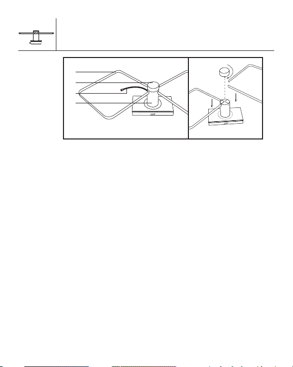
Assembly of Your TV4
1
2
3
4
2
1. Receiving Elements
2. Center Cap
3. Coaxial Cable
4. Center Control Arm
Assembly:
As shown above, simply insert the receiving
elements into the center control arm and handscrew the center cap, making sure you have
a snug fit.
Page 4

TV4
VHF/UHF
VHF
UHF
Installing Your TV4
Connecting your TV4
There are two ways to connect your TV4. This will depend
on your model of television.
For Televisions with One 75 Ohm Input for VHF and UHF:
1. Connect the coaxial cable from your TV4 to the
“F” connector input marked VHF/UHF on your TV.
See Fig.1.
For Televisions with Separate 75 Ohm
VHF and UHF Inputs:
1. Attach the band separator (included) to the coaxial
cable attached to your TV4.
2. Screw in the VHF connector from the band separator to
the VHF input on your TV or VCR.
3. Attach the 300 ohm twin wire from the band separator
to the two screws marked UHF. See Fig.2.
Band
Separator
3
Fig. 1
Fig. 2
Page 5

TV4
Operating Your TERK TV4
Low-Profile Indoor Antenna
Holding the top of the center control arm, simply rotate
the antenna to seek the best quality picture.
Please Note:
1. Do not force the center control arm past its
normal rotation positions.
2. Do not place your TV4 near large metal objects or
appliances that would create interference.
2. Do not lift your TV4 by its receiving elements or place
objects on them.
4. Late model televisions have on-screen menu controls
for viewing VHF/UHF “Off-Air” or cable broadcasts.
Please ensure that this menu control is at the proper
“Off-Air” position.
4
Page 6

TV4
Locating Your TV4
Your TV4 is a precision instrument and should be
placed in a location that is best for receiving TV signals.
It can be placed on top of any standard TV for
ease of adjustment.
5
Page 7

TV4
6
Frequently Asked Questions
Q. I have a cable ready TV. Why am I not getting any
channels above 13?
A. The tuners inside of cable ready TVs have two modes.
One mode is for cable and the other mode is for
antenna. When the TV is in cable mode, and you are
using an antenna, you will not be able to receive any
channels above 13. To fix this, simply access the menu
of your TV and switch the TV from Cable/CATV mode to
ANT/AIR mode.
Q. I have my TV in a metal cabinet. Will the antenna work
for me?
A. Any large metal objects will prevent the antenna signal
from reaching the antenna. You must place the antenna
outside of or above the metal cabinet.
Q. My home has aluminum siding/insulation. Where
should I place my antenna?
A. Place the antenna near a window to minimize
interference and improve your reception.
Q. Can I use my antenna in a basement?
A. TV signals cannot penetrate into basement locations
due to their lower elevation.
Please Note:
Other variables, which are not related to antenna
performance, can effect your reception. These include
distance from the source transmitting the desired
station, and man-made and natural conditions.
Example: Obstacles such as buildings between the
transmitting source and your antenna.
Page 8

Performance Specifications
For Customer Service
Visit Our Website At
www.audiovox.com
Product Information, Photos,
FAQ’s, Owner’s Manuals
Channels:
VHF: 2-13
UHF: 14-69
Operating Bandwidth: 54 MHz to 820 MHz
Output Impedance: 75 ohms
Dimensions (with elements): 43/4"H x 25"W x 12"D
Limited Warranty
Audiovox Corporation (Audiovox) warrants this product against defects in
materials or workmanship for one (1) year from the date of purchase. During
this period, this product will be replaced without charge. This warranty does
not cover any damage due to acts of nature, commercial use, accident, misuse,
abuse or negligence. This warranty is only valid in the USA. Replacement as
provided under this warranty is the exclusive remedy of the consumer.
Audiovox shall not be liable for any incidental or consequential damages for
breach of any express or implied warranty on this product, except to the extent
that limitations of this sort are prohibited by applicable law.
THERE ARE NO IMPLIED WARRANTIES OF MERCHANTABILITY OR FITNESS FOR
A PARTICULAR PURCHASE EXCEPT TO THE EXTENT THAT IMPLIED
WARRANTIES OR EITHER SORT ARE REQUIRED BY APPLICABLE LAW, AND IN
SUCH CASE, EACH WARRANTY IS LIMITED IN DURATION TO THE ONE YEAR.
For customer service and
technical information:: 1.800.290.6650
TERK and the TERK logo are registered trademarks of AUDIOVOX Corp. 57P008A
 Loading...