

Page 1
AA
CD-32CD-32
A
CD-32
AA
CD-32CD-32
DETACHABLEFRONTP ANEL
ELECTRONICALL Y-TUNEDAM/FM/MPXRADIO
WITHCOMP ACTDISCPLAYER
ANDQUARTZCLOCK
Page 2
INDEXINDEX
INDEX
INDEXINDEX
How To Use This Manual .......................................................................
Kit Information ........................................................................................
Universal and Import Car Installations ...................................................
Chrysler-Dodge-Plymouth Installations ..................................................
Chevrolet-Oldsmobile-Pontiac-Buick-GMC Cadillac-Saturn
Installations ............................................................................
Ford-Lincoln-Mercury Installations .........................................................
Radio Wiring ...........................................................................................
Speaker Wiring
Operating Instructions ............................................................................
Setting the Clock ....................................................................................
Error Codes ............................................................................................
Frequency Step Switch ...........................................................................
Specifications .........................................................................................
Troubleshooting ......................................................................................
Care and Maintenance ...........................................................................
Warranty .................................................................................................
Toll-Free AssistanceToll-Free Assistance
Toll-Free Assistance
Toll-Free AssistanceToll-Free Assistance
The installation and wiring connections for this unit are so simple, we doubt you'll need our
help, but, if you do, we're here to help you. Just call our toll-free telephone assistance line
at 1-800-645-7102 during days/hours shown.
Page 1
Page 2
Page 3,4
Page 5
Page 6
Page 7
Page 8
Page 9
Page 10-14
Page 15
Page 15
Page 15
Page 16
Page 17
Page 18
Back Page
11
1
11
TIME ZONE
DAY
MON.-FRI.
SATURDAY
PACIFIC
5:30AM - 4PM
6AM - 2PM
MOUNTAIN
6:30AM - 5PM
7AM - 3PM
CENTRAL
7:30AM -6PM
8AM -4PM
EASTERN
8:30AM - 7PM
9AM - 5PM
HELP!
1-800-645-7102
Monday- Friday
Saturday
HOW TO USE THIS MANUALHOW TO USE THIS MANUAL
HOW TO USE THIS MANUAL
HOW TO USE THIS MANUALHOW TO USE THIS MANUAL
1. Identify the make and year of the car in which you will be installing this sound system.
2. Refer to the Kit Listing and Kit Information sections on page 2 to determine if a kit is required.
3. If a kit is required, follow the directions in Kit Information section.
4. Follow the specific installation instructions for your particular make of car as listed in the
index.
8:30am-7:00pm Eastern
9:00am-5:00pm Eastern
Page 3

KIT INFORMATIONKIT INFORMATION
KIT INFORMATION
KIT INFORMATIONKIT INFORMATION
1. The years shown in the Kit Listing below are approximate. Always check the application chart at your
retail store to find information on your specific make, model and year of vehicle. If a kit is required,
read the description on the kit you intend to purchase to make sure it applies to your vehicle. If you
have any doubts or questions, call our toll-free "HELP" line.
2. The kits shown below are Audiovox kits. Your retailer may sell kits made by other manufacturers which
may also be usable to install this radio. Always check the kit application before purchasing it to make
sure it will work with your vehicle.
3. If you believe you need a kit but cannot find a retail store where it is available, call our toll-free "HELP"
line.
KIT LISTINGKIT LISTING
KIT LISTING
KIT LISTINGKIT LISTING
VEHICLE TYPE
Chevrolet-Oldsmobile-Buick-Pontiac-Cadillac-Saturn
1981 and Older ............................................................
1982 and Newer ...........................................................
Chevrolet-GMC Full Size Vans
1988 and Newer ............................................................
Chevrolet-GMC Full Size Pickups
1988 and Newer ............................................................
Chrysler-Dodge-Plymouth
U.S. Built 1974 and Newer ............................................
Imported .......................................................................
KIT REQUIREMENT/NOTES
Installation Not Possible
AX-93-FCGM
AX-88-CHV
AX-88-CHT
AX-93-FCGM
Refer to In-Store Chart
Ford-Lincoln-Mercury
1984 and Older .............................................................
1985 and Newer ............................................................
Jeep-Eagle
1984 and Newer ............................................................
IMPORT CARSIMPORT CARS
IMPORT CARS
IMPORT CARSIMPORT CARS
Due to the wide variety of import cars and the different installations required, this manual does not show
typical installations in these vehicles. However, this sound system can be installed in many import cars
by following the "Universal Installation" section on pages 3 and 4. Check the application chart at your retail
store or call our toll-free "HELP" line for specific information on your particular car.
IMPORTS:
Acura-Audi-BMW-Daihatsu-Fiat-Honda-Hyundai
Mercedes-Peugeot-Porsche-Saab-Subaru
Volkswagen-Volvo-Yugo ..............................................
Datsun-Nissan ..............................................................
Mazda ..........................................................................
Toyota ..........................................................................
For vehicles not listed or more specific information, refer to the in-store application chart or call our "HELP"
line.
Will Fit Most Years; Some Require
Filing of Dash
Refer to In-Store Chart
Professional Installation Recommended
Professional Installation Recommended
Installation Not Possible
AX-93-FCGM
Filing of Dash Required
22
2
22
Page 4
UNIVERSAL INSTALLATION AND IMPORT CAR INSTALLATIONUNIVERSAL INSTALLATION AND IMPORT CAR INSTALLATION
UNIVERSAL INSTALLATION AND IMPORT CAR INSTALLATION
UNIVERSAL INSTALLATION AND IMPORT CAR INSTALLATIONUNIVERSAL INSTALLATION AND IMPORT CAR INSTALLATION
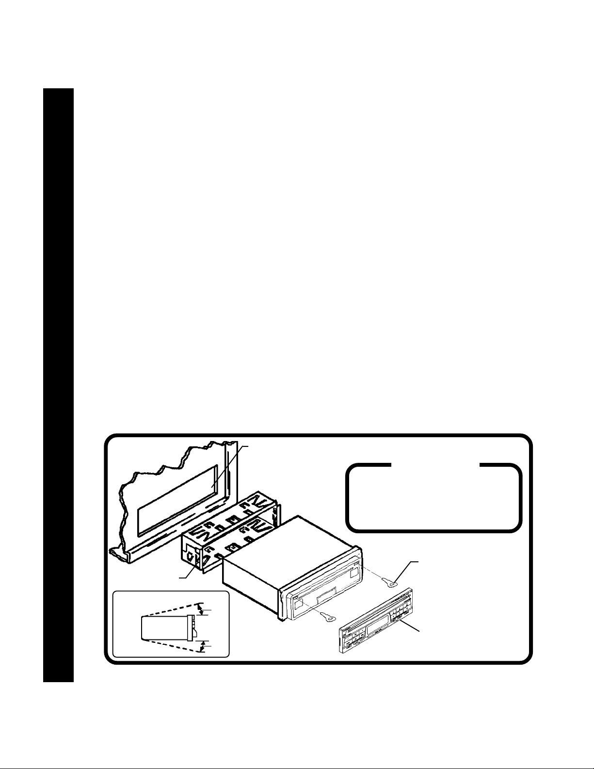
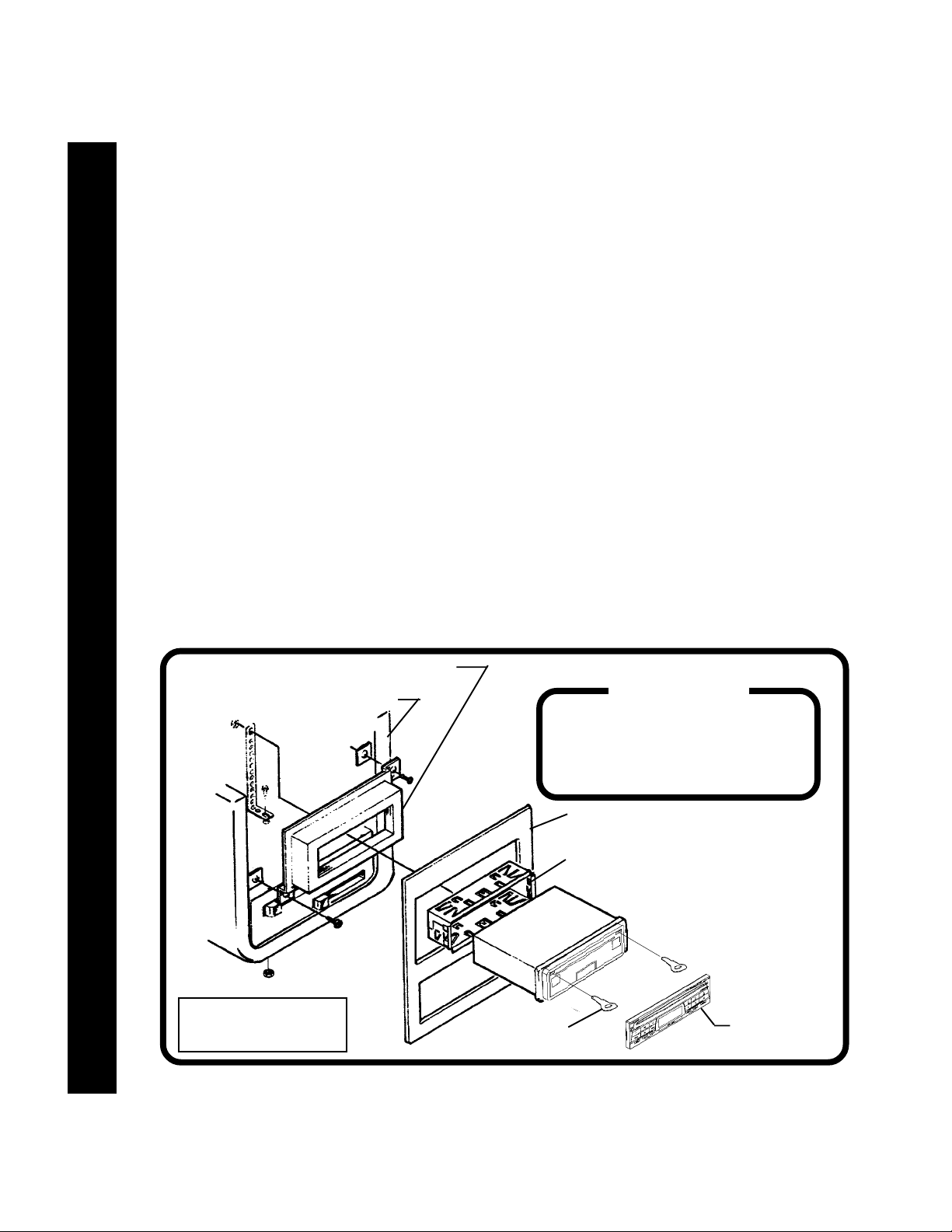
This installation is designed for cars, trucks, vans, and boats that have an existing radio opening that is
no larger than the size shown on the template provided (182mm wide x 53mm high). If the opening is
smaller than required, you can use a file to enlarge it to match the template, using the slots on the template
as a guide. If you have no existing radio opening, use the template to accurately cut the required size
as per the slots on the template.
CAUTION: 1. DO NOT CUT OR FILE THE OPENING TO THE OUTER EDGES OF THE TEMPLATE!
2. FOR PROPER OPERATION OF THE CD PLAYER, THE CHASSIS MUST BE WITHIN 20°
OF HORIZONTAL. MAKE SURE THE UNIT IS MOUNTED WITHIN THIS LIMITATION.
1. Inspect the Existing Radio Opening:
A. Use the radio opening template (supplied) to make sure the dashboard opening is the proper size.
If your vehicle does not have an existing opening of this size, it will be necessary to cut or file the
opening to these dimensions.
B. Check that there will be sufficient space behind the dashboard for the radio chassis.
2. Prepare theRadio for installation:
A. Carefully check the radio chassis for any shipping screws that are labeled "Remove Before
Installation" and remove them as necessary.
B. Remove the detachable front panel if it is attached to the chassis, as explained in the Operating
Instructions section of this manual.
C. Using the 2 removal tools (supplied), remove the mounting sleeve from the radio chassis as shown
in the diagram below.
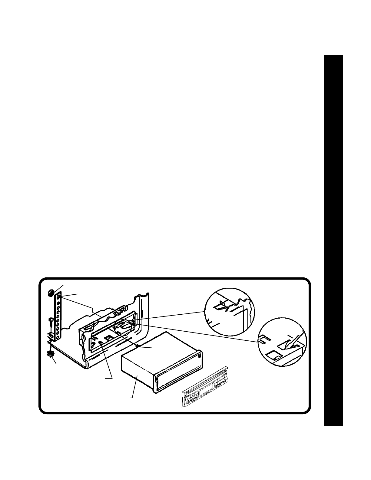
3. Mounting the Radio Sleeve:
A. Check the dashboard opening size by sliding the mounting sleeve into it. If the opening is not large
enough, carefully cut or file as necessary until the sleeve easily slides into the opening. Do not
force the sleeve into the opening or cause it to bend or bow.
B. Locate the series of bend tabs along the top, bottom, and sides of the mounting sleeve. With the
sleeve fully inserted in the dashboard opening, bend as many of the tabs outward as necessary
so that the sleeve is firmly secured to the dashboard.
UNIVERSAL INSTALLATION AND IMPORT CAR INSTALLATIONUNIVERSAL INSTALLATION AND IMPORT CAR INSTALLATION
UNIVERSAL INSTALLATION AND IMPORT CAR INSTALLATIONUNIVERSAL INSTALLATION AND IMPORT CAR INSTALLATION
UNIVERSAL INSTALLATION AND IMPORT CAR INSTALLATION
MOUNTINGSLEEVE
MOUNTINGANGLELIMITATION
SIDEVIEW
OF
CHASSIS
33
3
33
20°
MAX.
FRONT
PANEL
MAX.
USETEMPLATETOCHECKOPENING SIZE
ORTO CUTOPENING INSOLID
DASHBOARDS
HELP!
1-800-645-7102
Monday- Friday
Saturday
RADIO
20°
8:30am-7:00pm Eastern
9:00am-5:00pm Eastern
REMOVALTOOLS
REMOVABLEFRONTPANEL
(REFERTOOPERATING
INSTRUCTIONSFORREMOVAL)
Page 5
UNIVERSAL INSTALLATION AND IMPORT CAR INSTALLATIONUNIVERSAL INSTALLATION AND IMPORT CAR INSTALLATION
UNIVERSAL INSTALLATION AND IMPORT CAR INSTALLATION
UNIVERSAL INSTALLATION AND IMPORT CAR INSTALLATIONUNIVERSAL INSTALLATION AND IMPORT CAR INSTALLATION
4. Wire the Radio to the Vehicle's Wiring:
A. Place radio in front of dashboard opening so that wiring can be brought through the mounting sleeve.
B. Carefully follow the diagrams on pages 8 and 9 or 10 to wire the radio, making certain all connections
are secure and insulated with wire nuts or electrical tape to insure proper operation of the unit.
C. After completing the wiring, re-attach the front panel to the chassis and turn the unit on to confirm
operation (ignition switch must be "on"). If unit does not operate, re-check all wiring until problem
is corrected.
D. Once proper operation is achieved, turn off ignition switch, remove front panel, and proceed with
final mounting of the radio.
5. Installing the Radio in the Mounting Sleeve:5. Installing the Radio in the Mounting Sleeve:
5. Installing the Radio in the Mounting Sleeve:
5. Installing the Radio in the Mounting Sleeve:5. Installing the Radio in the Mounting Sleeve:
A. Carefully slide the radio into the mounting sleeve until it is fully seated and the side spring clips snap
in place.
B. Attach one end of the perforated strap (supplied) to the screw stud on the rear of the radio using
the hex nut provided.
C. Fasten the other end of the perforated strap to a secure part of the dashboard either above or below
the radio using the screw and hex nut provided.
CAUTION: The rear of the radio must be supported with the strap to prevent possible damage to the
dashboard from the weight of the radio or improper operation of the radio due to vibration.
D. Re-attach the front panel to the chassis and check operation of the unit by referring to the Operating
Instructions section of this manual.
6. Removing the Radio:
A. Should it be necessary to remove the radio for servicing or other reasons, first remove the
detachable front panel.
B. Remove the rear support strap by taking off the hex nut securing it to the screw stud on the rear
of the chassis.
C. Use the 2 removal tools (supplied) to disengage the spring clips and pull the radio out of the mounting
sleeve.
UNIVERSAL INSTALLATION AND IMPORT CAR INSTALLATION
UNIVERSAL INSTALLATION AND IMPORT CAR INSTALLATIONUNIVERSAL INSTALLATION AND IMPORT CAR INSTALLATION
UNIVERSAL INSTALLATION AND IMPORT CAR INSTALLATIONUNIVERSAL INSTALLATION AND IMPORT CAR INSTALLATION
HEXNUT
PERFORATEDSTRAP
HEXNUT
BENDTABSTOSECURE
SLEEVETODASH
SLIDERADIOINTOSLEEVE
SCREWSTUD
BENDTOP
TABSUPWARD
BENDBOTTOM
TABSDOWNWARD
44
4
44
Page 6
CHRYSLER-DODGE-PLYMOUTH INSTALLATIONCHRYSLER-DODGE-PLYMOUTH INSTALLATION
CHRYSLER-DODGE-PLYMOUTH INSTALLATION
CHRYSLER-DODGE-PLYMOUTH INSTALLATIONCHRYSLER-DODGE-PLYMOUTH INSTALLATION
All U.S. Made Cars, Trucks, and Vans Built Since 1974All U.S. Made Cars, Trucks, and Vans Built Since 1974
All U.S. Made Cars, Trucks, and Vans Built Since 1974
All U.S. Made Cars, Trucks, and Vans Built Since 1974All U.S. Made Cars, Trucks, and Vans Built Since 1974
Important-This radio cannot be installed in any U.S. made Chrysler, Dodge, or Plymouth without an
installation kit. Refer to Kit Listings on page 2 for the required kit. Complete kit installation is explained
in the instructions included with the kit.
CAUTION: 1. DO NOT CUT OR FILE THE OPENING TO THE OUTER EDGES OF THE TEMPLATE!
2. FOR PROPER OPERATION OF THE CD PLAYER, THE CHASSIS MUST BE WITHIN 20° OF
HORIZONTAL. MAKE SURE THE UNIT IS MOUNTED WITHIN THIS LIMITATION.
1. Remove Existing Radio:1. Remove Existing Radio:
1. Remove Existing Radio:
1. Remove Existing Radio:1. Remove Existing Radio:
A. Remove existing radio dash trim panel surrounding the radio opening. This panel is usually secured
by screws and/or snap-in clips.
B. Remove the two large screws used to secure radio to the sub-dashboard.
Helpful Hint: If you do not have an existing radio, you will find the radio opening is covered by a
disposable cover plate.
C. Pull the radio forward to access the wiring and antenna cables plugged into the rear of the chassis.
D. Un-plug the wiring harness(es) and antenna cable and remove the radio.
2. Install the New Radio:2. Install the New Radio:
2. Install the New Radio:
2. Install the New Radio:2. Install the New Radio:
A. Following the instructions included with the installation kit, secure the sleeve from the radio to the
mounting plate from the kit as explained on page 3.
B. Install the sleeve/mounting plate assembly to the sub-dashboard as per the instructions with the
installation kit.
C. Replace the dashboard trimpanel.
D. Following the instructions of steps 4 and 5 on page 4, carefully wire the radio and complete
installation into the mounting sleeve.
CHRYSLER-DODGE-PLYMOUTH INSTALLATIONCHRYSLER-DODGE-PLYMOUTH INSTALLATION
CHRYSLER-DODGE-PLYMOUTH INSTALLATIONCHRYSLER-DODGE-PLYMOUTH INSTALLATION
CHRYSLER-DODGE-PLYMOUTH INSTALLATION
AMOUNTINGKITISREQUIRED
55
5
55
FORTHISINSTALLATION
MOUNTINGPLATEFROMKIT
(NOTINCLUDEDWITHRADIO)
SUB-DASHBOARD(RADIOAREA)
IMPORTANT
RADIO
REMOVALTOOLS
HELP!
1-800-645-7102
Monday- Friday
Saturday
FACTORYDASHPANEL
MOUNTINGSLEEVE
8:30am-7:00pm Eastern
9:00am-5:00pm Eastern
INSTALLRADIOUSINGSAME
PROCEDUREASEXPLAINED
ONPAGES 3AND 4
DETACHABLE
FRONTPANEL
Page 7

CHEVROLET-OLDSMOBILE-BUICK-PONTIAC-GMC-CADILLAC-SATURN INSTALLATIONCHEVROLET-OLDSMOBILE-BUICK-PONTIAC-GMC-CADILLAC-SATURN INSTALLATION
CHEVROLET-OLDSMOBILE-BUICK-PONTIAC-GMC-CADILLAC-SATURN INSTALLATION
CHEVROLET-OLDSMOBILE-BUICK-PONTIAC-GMC-CADILLAC-SATURN INSTALLATIONCHEVROLET-OLDSMOBILE-BUICK-PONTIAC-GMC-CADILLAC-SATURN INSTALLATION
All U.S. Made Cars, Trucks, and Vans Built Since 1982All U.S. Made Cars, Trucks, and Vans Built Since 1982
All U.S. Made Cars, Trucks, and Vans Built Since 1982
All U.S. Made Cars, Trucks, and Vans Built Since 1982All U.S. Made Cars, Trucks, and Vans Built Since 1982
Important-This radio cannot be installed in any "GM" vehicle without an installation kit. Refer to Kit Listings
on page 2 for the required kit. Complete kit installation is explained in the instructions included with kit. This
radio cannot be installed in GM vehicles built before 1982.
CAUTION: 1. DO NOT CUT OR FILE THE OPENING TO THE OUTER EDGES OF THE TEMPLATE!
2. FOR PROPER OPERATION OF THE CD PLAYER, THE CHASSIS MUST BE WITHIN 20° OF
HORIZONTAL. MAKE SURE THE UNIT IS MOUNTED WITHIN THIS LIMITATION.
1. Remove Existing Radio:1. Remove Existing Radio:
1. Remove Existing Radio:
1. Remove Existing Radio:1. Remove Existing Radio:
A. Remove existing radio dash trim panel surrounding the radio opening. This panel is usually secured
by screws and/or snap-in clips.
B. Remove the screws used to secure radio to the sub-dashboard.
Helpful Hint: If you do not have an existing radio, you will find the radio opening is covered by a
disposable cover plate.
C. Pull the radio forward to access the wiring and antenna cables plugged into the rear of the chassis.
D. Un-plug the wiring harness(es) and antenna cable and remove the radio.
2. Install the New Radio:2. Install the New Radio:
2. Install the New Radio:
2. Install the New Radio:2. Install the New Radio:
A. Following the instructions included with the installation kit, secure the sleeve from the radio to the
mounting plate from the kit as explained on page 3.
B. Install the sleeve/mounting plate assembly to the sub-dashboard as per the instructions with the
installation kit.
C. Replace the dashboard trimpanel.
D. Following the instructions of steps 4 and 5 on page 4, carefully wire the radio and complete installation
into the mounting sleeve.
CHEVROLET-OLDS-BUICK-PONTIAC-GMC-CADILLAC-SATURN INSTALLATION
CHEVROLET-OLDS-BUICK-PONTIAC-GMC-CADILLAC-SATURN INSTALLATIONCHEVROLET-OLDS-BUICK-PONTIAC-GMC-CADILLAC-SATURN INSTALLATION
CHEVROLET-OLDS-BUICK-PONTIAC-GMC-CADILLAC-SATURN INSTALLATIONCHEVROLET-OLDS-BUICK-PONTIAC-GMC-CADILLAC-SATURN INSTALLATION
AMOUNTINGKITISREQUIRED
IMPORTANT
FORTHISINSTALLATION
SUB-DASHBOARD
(RADIOAREA)
MOUNTINGPLATEFROMKIT
(NOTINCLUDEDWITHRADIO)
DETACHABLEFRONTPANEL
INSTALLRADIOUSINGSAME
PROCEDUREASEXPLAINED
ONPAGES 3AND 4
FACTORYDASHPANEL
MOUNTINGSLEEVE
REMOVALTOOLS
RADIO
66
6
66
Page 8

FORD-LINCOLN-MERCURY INSTALLATIONFORD-LINCOLN-MERCURY INSTALLATION
FORD-LINCOLN-MERCURY INSTALLATION
FORD-LINCOLN-MERCURY INSTALLATIONFORD-LINCOLN-MERCURY INSTALLATION
All U.S. Made Cars, Trucks, and Vans Built Since 1985All U.S. Made Cars, Trucks, and Vans Built Since 1985
All U.S. Made Cars, Trucks, and Vans Built Since 1985
All U.S. Made Cars, Trucks, and Vans Built Since 1985All U.S. Made Cars, Trucks, and Vans Built Since 1985
Important-Measure the size of your existing radio opening. If it is no larger than the size shown on the
template provided, you can install the radio as explained on pages 3 and 4. If the opening is larger, you
must use a kit. See Kit Listing on page 2. This radio cannot be installed in Ford cars built prior to 1985.
CAUTION: 1. DO NOT CUT OR FILE THE OPENING TO THE OUTER EDGES OF THE TEMPLATE!
2. FOR PROPER OPERATION OF THE CD PLAYER, THE CHASSIS MUST BE WITHIN 20° OF
HORIZONTAL. MAKE SURE THE UNIT IS MOUNTED WITHIN THIS LIMITATION.
1. Remove Existing Radio:1. Remove Existing Radio:
1. Remove Existing Radio:
1. Remove Existing Radio:1. Remove Existing Radio:
A. Remove existing radio dash trim panel surrounding the radio opening. This panel is usually
secured by screws and/or snap-in clips.
B. Remove the screws used to secure radio to the sub-dashboard.
Helpful Hint: If you do not have an existing radio, you will find the radio opening is covered by
a disposable cover plate.
C. Pull the radio forward to access the wiring and antenna cables plugged into the rear of the chassis.
D. Un-plug the wiring harness(es) and antenna cable and remove the radio.
2. Install the New Radio:2. Install the New Radio:
2. Install the New Radio:
2. Install the New Radio:2. Install the New Radio:
A. If a kit is not required, follow the instructions on pages 3 and 4. If a kit is required, follow the
instructions included with the kit and secure the sleeve from the radio to the mounting plate from
the kit as explained on page 3.
B. Install the sleeve/mounting plate assembly to the sub-dashboard as per the instructions with the
installation kit.
C. Replace the dashboard trimpanel.
FORD-LINCOLN-MERCURY INSTALLATIONFORD-LINCOLN-MERCURY INSTALLATION
FORD-LINCOLN-MERCURY INSTALLATIONFORD-LINCOLN-MERCURY INSTALLATION
FORD-LINCOLN-MERCURY INSTALLATION
D. Following the instructions of steps 4 and 5 on page 4, carefully wire the radio and complete
installation into the mounting sleeve.
77
7
77
AMOUNTINGKITISREQUIRED
IMPORTANT
FORTHISINSTALLATION
SUB-DASHBOARD
(RADIOAREA)
MOUNTINGPLATEFROMKIT
(NOTINCLUDEDWITHRADIO)
HELP!
1-800-645-7102
Monday- Friday
Saturday
FACTORYDASHPANEL
MOUNTINGSLEEVE
RADIO
8:30am-7:00pm Eastern
9:00am-5:00pm Eastern
INSTALLRADIOUSINGSAME
PROCEDUREASEXPLAINED
ONPAGES 3AND 4
REMOVALTOOLS
DETACHABLE
FRONTPANEL
Page 9
RADIO WIRINGRADIO WIRING
RADIO WIRING
RADIO WIRINGRADIO WIRING
REFER TO PAGE 9 FOR SPEAKER WIRING
RADIO WIRING
RADIO WIRINGRADIO WIRING
RADIO WIRINGRADIO WIRING
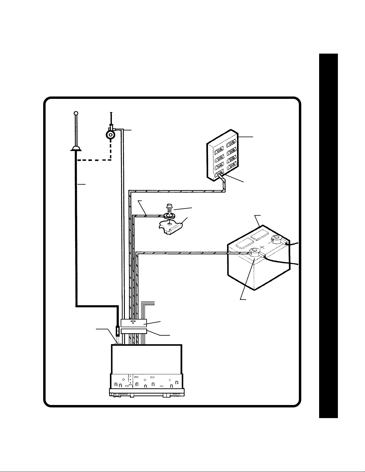
ANTENNA
AUTOMATIC
ANTENNA
EXISTING
ANTENNA
CABLE
PINK
IMPORTANT
THEPINKWIRE CANBEUSED
TOREMOTELYACTIVATE AN
AUTOMATICANTENNAORAN
EXTERNALAMPLIFIER (SEE
ANTENNA ORAMPLIFIER
MANUAL)
ORANGEw/WHITESTRIPE
BLACKw/WHITESTRIPE
METALPARTOFDASH
(DRILLHOLEIFNECESSARY)
GREENw/WHITESTRIPE
IMPORTANT
THISWIREMUSTBECONNECTEDASSHOWN
ORRADIOWILLNOTOPERATE PROPERLY
CAR
FUSEBLOCK
"RADIO"OR
"ACCESSORY"FUSE
SCREW
CARBATTERY
ANTENNASOCKET
ONREAROFRADIO
SEEPAGE9FORSPEAKER WIRING
(4PAIRS OFGREYWIRES)
14PIN PLUG
MATING14PINSOCKET
RADIO
POSITIVE (+)TERMINAL
12VOLTBATTERY
88
8
88
Page 10

SPEAKER WIRINGSPEAKER WIRING
SPEAKER WIRING
SPEAKER WIRINGSPEAKER WIRING
REFER TO PAGE 8
FOR RADIO WIRING
SPEAKER WIRINGSPEAKER WIRING
SPEAKER WIRINGSPEAKER WIRING
SPEAKER WIRING
RCAJACKS
FORUSEWITHOPTIONAL
EXTERNALAMPLIFIERS
RED=RIGHTCHANNEL
WHITE=LEFTCHANNEL
DRIVER'SSIDE
LEFTFRONTSPEAKER
THE AMPLIFIERS IN THIS RADIO ARE ONLY DESIGNED FOR USE WITH 4 SPEAKERS.
NEVER COMBINE (BRIDGE) OUTPUTS FOR USE WITH 2 SPEAKERS.
NEVER GROUND NEGATIVE SPEAKER LEADS TO CHASSIS GROUND.
FAILURE TO WIRE EXACTLY AS SHOWN BELOW MAY CAUSE ELECTRICAL DAMAGE TO THE RADIO.
RADIO
WARNING!
MATING14PINSOCKET
14PIN PLUG
SEEPAGE8FOR
RADIOWIRING
(PINK,BLACKw/WHITE,
ORANGEw/WHITEAND
GREENw/WHITE)
PASSENGER'SSIDE
RIGHTFRONTSPEAKER
99
9
99
GREYw/WHITE STRIPE
GREYw/REDSTRIPE
DRIVER'SSIDE
LEFTREARSPEAKER
GREY
GREY
GREYw/BLUESTRIPE
GREY
GREY
GREYw/YELLOWSTRIPE
HELP!
1-800-645-7102
Monday- Friday
Saturday
8:30am-7:00pm Eastern
9:00am-5:00pm Eastern
PASSENGER'SSIDE
RIGHTREARSPEAKER
Page 11

OPERATING INSTRUCTIONSOPERATING INSTRUCTIONS
OPERATING INSTRUCTIONS
OPERATING INSTRUCTIONSOPERATING INSTRUCTIONS
1 POWER OFF BUTTON
Press this button to turn the unit off. Use the Radio
On/Band Selector button bl or CD Mode Selector
cl to turn the unit on.
2 VOLUME / LEVEL CONTROLS
To increase the volume level, press the + button.
The volume will increase and the level will be
shown by the bars under the “VOL” indication on the
display panel. To increase the volume quickly,
keep the button pressed. To decrease the volume
level, press the - button. Keep the button pressed
to decrease the volume quickly. The display will
automatically return to the normal indication 5
seconds after the last volume adjustment or when
another function is activated. These controls are
also used in conjunction with the Select button 3
to adjust the treble, bass, balance and fader levels
as described in 4 , 5 , 6 , and 7 .
3 SELECT BUTTON (SEL)
This button is used to select the audio function
(volume, bass, treble, balance or fade) to be ad-
justed using the Level Control 2 . Pressing the
Select button once will set the unit for bass adjustment (“BAS” will appear on the display panel).
Pressing the button additional times will select
treble adjustment (“TRE” on display panel), balance
(“BAL”), fader (“FAD”), and volume (“VOL”). The
display will return to the normal indication 5 seconds
after the last adjustment or when another function is
activated.
4 BASS CONTROL
To adjust the bass level, first select the Bass mode
by pressing the Select button 3 until the “BAS”
indication appears on the display panel. Within 5
seconds of choosing the Bass mode, press the + or
- buttons of the Level Control 2 to adjust the bass
response as desired. The bass level will be shown
by the bars on the display panel from a minimum of
----- to a maximum of ----- (a single bar in the center
of the display represents flat response). The display
will automatically return to the normal indication 5
seconds after the last adjustment or when another
function is activated.
5 TREBLE CONTROL
To adjust the treble level, first select the Treble
mode by pressing the Select button 3 until the
“TRE” indication appears on the display panel.
Within 5 seconds of choosing the Treble mode,
press the + or - buttons of the Level Control 2 to
OPERATING INSTRUCTIONS
OPERATING INSTRUCTIONSOPERATING INSTRUCTIONS
OPERATING INSTRUCTIONSOPERATING INSTRUCTIONS
1010
10
1010
Page 12

adjust the treble response as desired. The treble
level will be shown by the bars on the display panel
from a minimum of ----- to a maximum of ----- (a
single bar in the center of the display represents
flat response). The display will automatically
return to the normal indication 5 seconds after the
last adjustment or when another function is activated.
6 LEFT/RIGHT BALANCE CONTROL
To adjust the left-right speaker balance, first select
the Balance mode by pressing the Select button 3
until the “BAL” indication appears on the display
panel. Within 5 seconds of choosing the Balance
mode, press the - button of the Level Control 2 to
adjust the stereo balance to the left channel speak-
OPERATING INSTRUCTIONSOPERATING INSTRUCTIONS
OPERATING INSTRUCTIONSOPERATING INSTRUCTIONS
OPERATING INSTRUCTIONS
ers or the + button of the control to adjust it to the
right channel speakers. The balance position will
be shown by the bars on the display panel from
L----- (full left) to -----R (full right). When the
volume level between the left and right speakers is
equal, L - R will be shown on the display panel.
The display will automatically return to the normal
indication 5 seconds after the last adjustment or
when another function is activated.
7 FRONT/REAR FADER CONTROL
To adjust the front-rear speaker balance, first
select the Fader mode by pressing the Select
button 3 until the “FAD” indication appears on the
display panel. Within 5 seconds of choosing the
Fader mode, press the - or the + buttons of the
Level Control 2 to adjust the front-rear speaker
levels as desired. The fader position will be shown
by the bars on the display panel from R----- (full
rear) to -----F (full front). When the volume level
between the front and rear speakers is equal,
R - F will be shown on the display panel. The
display will automatically return to the normal
indication 5 seconds after the last adjustment or
when another function is activated.
1111
11
1111
8 LOUDNESS CONTOUR
When listening to music at low volume levels, this
feature will boost the bass and treble ranges to
compensate for the characteristics of human hearing. Press the button to activate this feature as
indicated by “LOUD” on the display panel. Pressing
the button again will de-activate the function and
“LOUD” will disappear from the display.
9 AUDIO MUTE
This button is used to mute the volume from the
system. By pressing the button, the indication
“MUTE” will appear on the display panel and the
volume will be muted. When in the Mute mode, the
Volume/Level Controls 2 and Select button 3
will be disabled. Press the Mute button again to
return to the volume level setting in use before the
Mute function was activated.
bl RADIO ON
AM/FM BAND SELECTOR
Press this button to turn the radio on.
During radio play, each time the button is pressed,
the radio band changes. The indications “AM1”,
“AM2”, “FM1”, “FM2”, or “FM3” will appear on the
display panel according to your selection.
During CD play, pressing this button will change to
radio operation without ejecting the disc.
bm& bnMANUAL UP/DOWN TUNING ( / )
To manually select a radio station, momentarily
press the Up Tuning ( ) button bm to advance the
unit one digit higher or the Down Tuning ( ) button
bn to tune downward. Continue to press either
button to tune the radio rapidly in the selected
direction.
bo AUTOMATIC UP SEEK TUNING ( )
bp AUTOMATIC DOWN SEEK TUNING ( )
Pressing either button will activate the Automatic
Seek Tuning function in the selected direction. The
radio will seek the next available station and stop at
that frequency. The Seek function can also be
stopped by pressing the button again or activating
any other tuning function.
Page 13

bqAUTO-STORE TUNING(AS)
PRE-SET SCAN TUNING (PS)
Press this button momentarily to scan the 6 stations in the pre-set memories of the band in use.
The unit will stop at each pre-set station for 5
seconds before continuing to the next pre-set
station (the pre-set number on the display panel
will flash during Pre-Set Scan operation). Press
the button again momentarily to stop Pre-Set Scan
operation and remain on the selected frequency.
Pressing the button for longer than 2 seconds will
activate the Auto-Store Tuning feature. The radio
will automatically scan the band in use and enter
strong stations into the pre-set memory positions
for that band. If you have already set the pre-set
memories of that band to your favorite stations,
activating the Auto-Store Tuning feature will erase
those stations and enter the new strong stations.
This feature is most useful when travelling in a new
area where you are not familiar with the local
stations.
will appear on the display panel) and only strong
(local) stations will be received during Automatic
Seek Tuning. Pressing the button again will select
the Distant setting (“LOC” will disappear from the
display panel) and the radio will stop at a wider
range of signals, including weaker (more distant)
stations.
During FM radio operation, this button is used to
select mono or stereo reception of the broadcast
signal. Under normal reception conditions, the unit
should be left in the stereo mode, as indicated by
“ST” on the display panel when listening to an FM
stereo signal. If the stereo signal is too weak for
comfortable listening, press the button to switch to
mono reception (the “ST” will disappear from the
display panel and “MONO” will appear). To return
to the stereo reception mode, press the button
again so that the “MONO” indication disappears
and the “ST” indication returns.
OPERATING INSTRUCTIONS
OPERATING INSTRUCTIONSOPERATING INSTRUCTIONS
OPERATING INSTRUCTIONSOPERATING INSTRUCTIONS
br STATION PRE-SET MEMORIES
To set any of the 6 pre-set memory buttons, use the
following procedure:
1. Turn the unit on and select the desired band.
2. Select the first station to be pre-set using the
Manual Up/Down bm & bnorAutomatic Up/
Down Seek Tuning functions bo& bp.
3. Press the pre-set button to be set and continue
to hold the button in. The volume will be
momentarily muted and then return and the
pre-set number will appear on the display panel.
The station is now set into the memory of that
pre-set button and can be re-called at any time
by momentarily pressing that button.
4. Repeat the above procedure for the remaining
5 pre-sets on the band in use and for the other
4 bands of the unit.
bs LOCAL/DISTANT - FM STEREO/MONO
SELECTOR (MO/LO)
This button is used to select the strength of the
signals (Local or Distant) at which the radio will
stop during Automatic Seek Tuning on the AM and
FM bands as well as FM Stereo or Mono reception
modes.
Press the button to select the Local setting (“LOC”
bt LIQUID CRYSTAL DISPLAY PANEL
The Liquid Crystal Display (LCD) panel displays
the frequency, time, and activated functions.
NOTE: It is a characteristic of LCD panels that, if
subjected to cold temperatures for an e x tended period of time, they may take longer
to illuminate than under normal conditions.
In addition, the visibility of the numbers on
the LCD may slightly decrease. The LCD
read-out will return to normal when the
temperature increases to a normal range.
buDISCSLOT
With the label surface facing up, gently insert the
disc into the slot until the soft-loading mechanism
engages and disc play begins. The DISC indication, track number and elapsed time will appear on
the display panel.
NOTE: This unit is designed for play of standard
5" (12cm) Compact Discs ONLY. Do not
attempt to use 3" (8cm) CD-Singles in this
unit, either with or without an adaptor, as
damage to the player and/or disc can
occur. Such damage will not be covered
by the Warranty on this product.
1212
12
1212
Page 14

cl CD MODE SELECTOR (CD)
Press this button to turn on the unit if a disc is
already loaded in the player.
When listening to radio with a disc loaded in the
unit ( DISC on the display panel), press this button
to return to disc play mode from the point at which
play was stopped.
cm FORWARD TRACK SELECT ( )
cn BACKWARD TRACK SELECT ( )
The Track Select functions are used to quickly
access the beginning of a particular track. Each
time the Forward Track Select ( ) button is
pressed, the next higher track number will be
selected as shown on the display panel. Similarly,
each time the Backward Track Select ( ) button
OPERATING INSTRUCTIONSOPERATING INSTRUCTIONS
OPERATING INSTRUCTIONSOPERATING INSTRUCTIONS
OPERATING INSTRUCTIONS
is pressed, the next lower track number will be
selected as shown on the display panel.
co & cp CUE/REVIEW FUNCTIONS ( / )
High-speed audible search to any section of the
disc can be made by the Cue and Review functions. Press and hold the Cue button ( ) to
advance rapidly in the forward direction or the
Review button ( ) to advance rapidly in the
backward direction. During either function, the
elapsed time within each track will automatically
be shown on the display panel.
cs RANDOM PLAY SELECTOR (RDM)
During disc play, press this button to play the tracks
on the disc in a random shuffled order (“RANDM”
will appear on the display panel). In Random Play
mode, the Forward Track Select cm will also select
tracks in the random order instead of the normal
progression. Backward Track Select cn will only
go back to the beginning of the track in play. The
Random Play mode can be cancelled by pressing
the button again (“RANDM” indication will disappear from the display panel) or by activating the
Intro-Scan cqor Repeat Play cr functions.
ct DISC EJECT ( )
Disc play is stopped, the disc is ejected and the unit
will change to radio operation by pressing this
button. If the disc is not removed from the unit
within 10 seconds of being ejected, it will automatically be re-loaded into the unit to prevent damage
( DISC will appear on the display panel). Pressing
the CD Mode Selector button cl again before
removing the disc will also re-load the disc into the
unit.
cu TIME/FREQUENCY DISPLAY SELECTOR
(DISP)
Press this button to call the time display on the
incorporated quartz clock. Press the button again
to return to radio frequency or disc display.
1313
13
1313
cq INTRO-SCAN SELECTOR (INT)
During disc play, press this button to play the first
10 seconds of each track on the disc (“INTRO” will
appear on the display panel). When a desired
track is reached, press the Intro-Scan button cq
again to cancel the function and play of the selected track will continue. Intro-Scan mode will
also be cancelled by activating the Repeat Play cr
or Random Play cs functions.
cr REPEAT PLAY SELECTOR (RPT)
During disc play, press this button to repeat the
play of the selected track (“RPT” will appear on the
display panel). Play of the track will continue to
repeat until the button is pressed again and the
“RPT” indication disappears from the display panel.
Repeat Play mode will also be cancelled by acti-
vating the Intro-Scan cq or Random Play cs
functions.
dl THEFT-DETERRENT L.E.D.
Located on the chassis behind the front panel, a
light-emitting diode (L.E.D.) will flash when the
panel is removed. The flashing light serves as a
visual warning to the would-be thief that the unit
has been disabled by removal of the front panel.
dmRE-SETBUTTON
A Re-Set button is located on the front of the
chassis (front panel must be removed to access
the button). The re-set circuitry is provided to
protect the microprocessor circuitry and should
only be activated under the following circumstances
as it will erase the time and radio station pre-set
memories.
1. Upon initial installation after all wiring is completed.
2. After the position of the frequency step switch on
the bottom of the chassis has been changed.
Page 15

3. If there is a malfunction of any of the switches
on the unit or of the CD player, pressing the ReSet button may clear the system and return to
normal operation.
dn FRONT PANEL RELEASE KNOB
This knob is used to release the mechanism that
holds the front panel to the chassis. To detach the
front panel, slide the button to the right so that the
left side of the panel is released. Grasp the
released side and pull it off of the chassis. To reattach the panel, position the right side of the panel
in place first and then press the left side of the
panel until the mechanism locks it into place.
NOTES ON USE OF FRONT PANEL
1. Make sure the front panel is right-side-up when
attaching it to the chassis as it cannot be
attached when up-side down.
2. Do not press very hard on the front panel when
attaching it to the chassis. No more than light
to moderate pressure should be needed.
3. When attaching the front panel, make sure the
right side is correctly engaged before pressing
the left side to lock it into position.
4. When taking the front panel with you, please use
the supplied carrying case to protect the panel
from dirt and damage.
OPERATING INSTRUCTIONS
OPERATING INSTRUCTIONSOPERATING INSTRUCTIONS
OPERATING INSTRUCTIONSOPERATING INSTRUCTIONS
DETACHING THE FRONT PANEL
Release Button
ATTACHING THE FRONT PANEL
Engage right
side first
1414
14
1414
Page 16

SETTING THE CLOCKSETTING THE CLOCK
SETTING THE CLOCK
SETTING THE CLOCKSETTING THE CLOCK
1. Turn the radio on so that the radio frequency or clock time is shown on the display panel.
2. Press and hold the Time/Frequency Display Selector button cu approximately 2 seconds until the
time display begins flashing.
3. While continuing to hold the Time/Frequency Display Selector button, press the Down Seek Tuning
button ( ) bp to adjust the hours and the “PM” indicator and the Up Seek Tuning button ( ) bo
to adjust the minutes to the correct time.
4. When the correct time is shown on the display panel, release the Time/Frequency Selector button.
ERROR CODESERROR CODES
ERROR CODES
ERROR CODESERROR CODES
If a problem should develop while operating the CD player, the following error codes may be displayed
on the display panel:
ER 1:
ER 2:
ER 3:
RST:
ROM:
If the suggested measures do not solve the problem, contact an approved warranty station near you for
further assistance.
This unit is supplied pre-set at the factory for reception of North American radio stations (10 KHz. channel
spacing on AM/200 KHz. spacing on FM). Use in other areas in the world may require different channel
spacing. A switch on the bottom of the chassis allows selection of 9 KHz. AM/50 KHz. FM channel
spacing. Slide the switch to the appropriate position using a small screwdriver blade. The Re-Set button
Indicates the disc is not loading or ejecting properly. Try re-loading or pressing the Eject
button again. Check the condition of the disc in use or try another disc.
Indicates an interface error between the disc mechanism and radio circuitry. Press the
Re-Set button dm and try again.
Indicates an error in the laser reading the disc. Eject the disc, make sure it is clean,
undamaged, and loaded correctly (label side up). Re-load the disc and check for proper
operation or try another disc.
Indicates a system error. Press the Re-Set button dm and try again.
Indicates that a computer CD-ROM has been loaded into the unit. Eject the disc and load
an audio CD.
FREQUENCY STEP SWITCHFREQUENCY STEP SWITCH
FREQUENCY STEP SWITCH
FREQUENCY STEP SWITCHFREQUENCY STEP SWITCH
dm on the front of the chassis must then be pressed to activate the change of channel spacing.
1515
15
1515
Page 17

SPECIFICATIONSSPECIFICATIONS
SPECIFICATIONS
SPECIFICATIONSSPECIFICATIONS
SPECIFICATIONS
SPECIFICATIONSSPECIFICATIONS
SPECIFICATIONSSPECIFICATIONS
Size:
Operating Voltage:
Output Power:
Output Wiring:
Output Impedance:
Low-Level Output:
Tuning Range:
Sensitivity:
FM Stereo Separation:
CD Frequency Response:
7" W x 2" H x 6-1/4" D
178 mm x 50 mm x 160 mm
12 volts DC, negative ground
64 watts maximum
(7 watts x 2 channels-front
25 watts x 2 channels-rear)
Floating-ground type designed for 4 speaker use.
CANNOT be used with 2 speakers.
RCA low-level outputs.
Compatible with 4-8 ohm speakers.
500 mv.
AM: 530-1,720 KHz. (10 KHz. step)
522-1,620 KHz. ( 9 KHz. step)
FM: 87.5-107.9 MHz. (200 KHz. step)
87.5-108.0 MHz. (50 KHz. step)
AM: 20 uv.
FM: 1.5 uv.
30 dB
20-20,000 Hz. ± 2dB
CD Signal/Noise Ratio:
CD Channel Separation:
CD Dynamic Range:
CD Distortion:
*Specifications are subject to change without notice.
>70 dB
>60 dB
>80 dB
<0.1% T.H.D.
1616
16
1616
Page 18

TROUBLESHOOTINGTROUBLESHOOTING
TROUBLESHOOTING
TROUBLESHOOTINGTROUBLESHOOTING
PROBLEM PROBABLE CAUSE CHECK FOLLOWING
Unit completely inoperative no
lights, no sound
Unit will not keep time or radio
station memory
TROUBLESHOOTINGTROUBLESHOOTING
TROUBLESHOOTINGTROUBLESHOOTING
TROUBLESHOOTING
Noise on both radio and CD
Noise on radio only
Poor FM reception and almost no
AM reception
No sound on one speaker
(both radio and CD)
Incorrect power connection
Blown fuse
Incorrect power connection
Blown fuse
Poor ground
Dirty or corroded battery posts
If problem also existed with previous radio you removed
Antenna
Antenna
Wiring
Speaker
Orange/White stripe wire to +12V ACC.
and Green/White stripe wire to +12V
battery
Check fuses in wires listed above and
check car fuse block
Green/White stripe wire is not connected
to a "live" +12V battery source
Check fuse in Green/White stripe wire
and at car's fuse block
Check Black/White stripe wire for proper
grounding
Clean and tighten connection
Consult your local garage mechanic-car
may need tune-up or noise filter
Check that antenna base is grounded.
Test with antenna disconnected. If noise
goes away, replace antenna
Replace antenna and antenna cable
Check speaker wiring
Test with good speaker
1717
17
1717
Poor sound-new unit
CD sound skips
Control Settings
Speakers or speaker wiring
Installation angle is greater than
20°
Disc player is not installed correctly
Dirty, scratched, or defective disc
Condensation on laser lens
Check balance and fader controls
Check rating of speakers for sufficient
power capacity
Check that speakers are in good
condition
Check that none of the speaker wires are
grounded
Check speaker wiring
Adjust the mounting angle to less than
20°
Make sure disc player is mounted securely
Clean disc if dirty; replace if badly
scratched or defective
Allow condensation to dry, then try again
Page 19

CARE AND MAINTENANCECARE AND MAINTENANCE
CARE AND MAINTENANCE
CARE AND MAINTENANCECARE AND MAINTENANCE
The radio section of your new sound system does not require any maintenance. We recommend you
keep this manual for reference on the many features found in this unit as well as how to set the clock.
The compact disc player section also requires no routine maintenance, but proper understanding of
its use and handling will help you obtain maximum enjoyment of its capabilities. The following points
should be observed:
When cleaning the interior of the vehicle, do not get water or cleaning fluids on the unit.
The CD player is a precision instrument and will not operate properly in extreme hot or cold. In
case of such conditions, wait until the interior temperature of the vehicle reaches a normal
temperature before using the player.
If the temperature inside the player gets too hot, a protective circuit will automatically stop play
of the disc. In this case, allow the unit to cool off before operating the player again.
Never insert anything other than a 5" (12 cm) compact disc into the player as the mechanism
can be damaged by foreign objects.
Do not attempt to use 3" (8 cm) CD-Single discs in this unit, either with or without an adaptor,
as damage to the player and/or disc may occur. Such damage will not be covered by the
Warranty on this product.
When not using the disc player, always remove the compact disc. Do not leave an ejected disc
sitting in the disc slot as this can expose it to sunlight and other causes of damage.
Do not attempt to open the unit chassis. There are no user serviceable parts or adjustments
inside.
When the vehicle warms up during cold weather or under damp conditions, moisture may
condense on the lens of the disc player. Should this occur, the player will not operate properly
until the moisture has evaporated.
The unit is designed with a vibration dampening CD mechanism to minimize interruption of disc
play due to normal vibration in a moving vehicle. When driving on very rough roads, however,
occasional sound skips may occur. This will not scratch or damage the disc and normal play
will resume when the rough conditions cease.
CARE AND MAINTENANCE
CARE AND MAINTENANCECARE AND MAINTENANCE
CARE AND MAINTENANCECARE AND MAINTENANCE
HANDLING COMPACT DISCS
Dirt, dust, scratches, and warpage can cause skips in the playback and deterioration of sound quality.
Please follow these guidelines to take care of your compact discs:
Use only compact discs with the mark.
Fingerprints, dust, and dirt should be carefully wiped off the disc’s playing surface (shiny side)
with a soft cloth.
Wipe in a straight motion from the inside to the outside of the disc.
Never use chemicals such as record sprays, household cleaners or thinner to clean compact
discs. Such chemicals can irreparably damage the disc’s surface.
Discs should be kept in their storage cases when not in use.
Do not expose discs to direct sunlight, high temperatures or high humidity for extended periods.
Do not stick paper, tape, or labels on the disc surfaces nor write on them with any type of marker.
1818
18
1818
Page 20

12 MONTH LIMITED WARRANTY
Applies to In-dash radios, radio/tape player and radio/CD player combinations, and CD Changers.
AUDIOVOX CORPORATION (the Company) warrants to the original retail purchaser of this product that should
this product or any part thereof, under normal use and conditions, be proven defective in material or workmanship
within 12 months from the date of original purchase, such defect(s) will be repaired or replaced with new or
reconditioned product (at the Company's option) without charge for parts and repair labor.
To obtain repair or replacement within the terms of this Warranty, the product is to be delivered with proof of warranty
coverage (e.g. dated bill of sale), specification of defect(s), transportation prepaid, to an approved warranty station.
For the location of the nearest warranty station to you, call toll-free to our control office:
IN U.S.A. 1-800-243-1311
IN CANADA 1-800-461-1772
This Warranty does not extend to the elimination of car static or motor noise, to correction of antenna problems,
to costs incurred for installation, removal, or reinstallation of the product, or damage to tapes, compact discs,
speakers, accessories, or vehicle electrical systems.
This Warranty does not apply to any product or part thereof which, in the opinion of the Company, has suffered
or been damaged through alteration, improper installation, mishandling, misuse, neglect, accident, or by removal
or defacement of the factory serial number/bar code label(s). THE EXTENT OF THE COMPANY'S LIABILITY
UNDER THIS WARRANTY IS LIMITED TO THE REPAIR OR REPLACEMENT PROVIDED ABOVE AND, IN NO
EVENT, SHALL THE COMPANY'S LIABILITY EXCEED THE PURCHASE PRICE PAID BY PURCHASER FOR
THE PRODUCT.
This Warranty is in lieu of all other express warranties or liabilities. ANY IMPLIED WARRANTIES, INCLUDING
ANY IMPLIED WARRANTY OF MERCHANTABILITY, SHALL BE LIMITED TO THE DURATION OF THIS
WRITTEN WARRANTY. ANY ACTION FOR BREACH OF ANY WARRANTY HEREUNDER INCLUDING ANY
IMPLIED WARRANTY OF MERCHANTABILITY MUST BE BROUGHT WITHIN A PERIOD OF 30 MONTHS FROM
DATE OF ORIGINAL PURCHASE. IN NO CASE SHALL THE COMPANY BE LIABLE FOR ANY CONSEQUENTIAL OR INCIDENTAL DAMAGES FOR BREACH OF THIS OR ANY OTHER WARRANTY, EXPRESS OR
IMPLIED, WHATSOEVER. No person or representative is authorized to assume for the Company any liability other
than expressed herein in connection with the sale of this product.
Some states do not allow limitations on how long an implied warranty lasts or the exclusion or limitation of incidental
or consequential damage so the above limitations or exclusions may not apply to you. This Warranty gives you
specific legal rights and you may also have other rights which vary from state to state.
U.S.A. : AUDIOVOX CORPORATION, 150 MARCUS BLVD., HAUPPAUGE, NEW YORK 11788 1-800-243-1311
CANADA: CALL 1-800-461-1772 FOR LOCATION OF WARRANTY STATION SERVING YOUR AREA
AUSTRALIA: AUDIOVOX PACIFIC PTY LTD., DOYLE AVENUE, UNANDERRA, NSW 2526 (042) 718-555
NEW ZEALAND: AUDIOVOX PACIFIC PTY LTD., UNIT B, 6 HENDERSON PLACE, PENROSE, AUCKLAND (09) 645-720
®
© 1996 Audiovox Corporation Hauppauge, NY 11788 Printed in China
Form No. 128-4785
 Loading...