

Page 1
OWNER’S MANUAL
READ
THIS
FIRST!
SIRMarine
DUAL MOUNT MARINE SIRIUS SA
TELLITE RADIO ANTENNA
Page 2

SIRMarine Owner’s Manual
Table of Contents
About Installation . . . . . . . . . . . . . . . . . . . . . . . . . . . . . . . . . . . . . . . . . . . . . . . . . . . . . . . . . . . . . . . 2
Introduction . . . . . . . . . . . . . . . . . . . . . . . . . . . . . . . . . . . . . . . . . . . . . . . . . . . . . . . . . . . . . . . . . . . . 3
Applications. . . . . . . . . . . . . . . . . . . . . . . . . . . . . . . . . . . . . . . . . . . . . . . . . . . . . . . . . . . . . . . . . . . . 4
Installation . . . . . . . . . . . . . . . . . . . . . . . . . . . . . . . . . . . . . . . . . . . . . . . . . . . . . . . . . . . . . . . . . . . . . 6
Parts for TERK SIRMarine Satellite Radio Antenna . . . . . . . . . . . . . . . . . . . . . . . . . . . . . . . . . . . 6
Recommended Tools and Supplies. . . . . . . . . . . . . . . . . . . . . . . . . . . . . . . . . . . . . . . . . . . . . . . 6
Installation Precautions and Tips . . . . . . . . . . . . . . . . . . . . . . . . . . . . . . . . . . . . . . . . . . . . . . . . 6
Installing the TERK SIRMarine Satellite Radio Antenna. . . . . . . . . . . . . . . . . . . . . . . . . . . . . . . . 7
Use and Care . . . . . . . . . . . . . . . . . . . . . . . . . . . . . . . . . . . . . . . . . . . . . . . . . . . . . . . . . . . . . . . . . 10
Troubleshooting . . . . . . . . . . . . . . . . . . . . . . . . . . . . . . . . . . . . . . . . . . . . . . . . . . . . . . . . . . . . . . . 10
Specifications . . . . . . . . . . . . . . . . . . . . . . . . . . . . . . . . . . . . . . . . . . . . . . . . . . . . . . . . . . . . . . . . . 10
Electrical Specifications . . . . . . . . . . . . . . . . . . . . . . . . . . . . . . . . . . . . . . . . . . . . . . . . . . . . . . 10
Mechanical Specifications . . . . . . . . . . . . . . . . . . . . . . . . . . . . . . . . . . . . . . . . . . . . . . . . . . . . 10
Quality and Performance Specifications. . . . . . . . . . . . . . . . . . . . . . . . . . . . . . . . . . . . . . . . . . 10
Limited Warranty . . . . . . . . . . . . . . . . . . . . . . . . . . . . . . . . . . . . . . . . . . . . . . . . . . . . . . . . . . . . . . 11
About Sirius Satellite Radio . . . . . . . . . . . . . . . . . . . . . . . . . . . . . . . . . . . . . . . . . . . . . . . . . . . . . 11
About Installation
Installation of marine audio components can require extensive experience with a variety of mechanical
and electrical procedures. Although the instructions in this guide explain how to install the TERK
SIRMarine Satellite Radio Antenna in a general sense, they do not show the exact installation methods
for your particular boat.
IMPORTANT: If you are not comfortable performing a complex installation, ask your local
marine audio dealer about professional installation options.
Introduction
The TERK SIRMarine Satellite Radio Antenna is a high-performance antenna designed specifically for
Sirius Satellite Radio reception on recreational marine craft such as fishing boats, sport boats, yachts,
and sailboats. Its features include:
• Rugged antenna to withstand high-vibration salt-water environment
• Dual mounting options:
– Through hole mounting for deck mount or mounting on any flat surface. Perfect for use on
small vessels.
– Bracket or mast mounting when used with the supplied threaded flange adaptor with the
standard 1”-14 marine thread. Perfect for larger vessels and sail boats. (Mounting bracket
and mast not included)
• Antenna supplied with 6 inch cable and gold plated TNC connector for ease of mounting. Also
includes 25 feet of RG174 coax cable terminated with gold plated TNC and SMB connectors
• Meets or exceeds all Sirius Satellite Radio mobile-antenna specifications
• Shock- and vibration-proof design
The TERK SIRMarine Satellite Radio Antenna is easy to install on most recreational marine craft.
Remember to save your sales receipt and this guide so both are available for future reference.
NOTE: To achieve best Sirius Satellite Radio reception, also refer to your SIRIUS radio’s
owner’s manual.
2 Table Of Contents
Introduction 3
Page 3
SIRMarine Owner’s Manual
TERK SIRMarine
Satellite Radio
Antenna
TERK SIRMarine
Satellite Radio Antenna
TERK SIRMarine
Satellite Radio
Antenna
TERK SIRMarine
Satellite Radio
Antenna
TERK SIRMarine
Satellite Radio
Antenna
Applications
The TERK SIRMarine Satellite Radio Antenna can be installed on a variety of recreational marine
craft, as shown below. For details, see Installation starting on page 6.
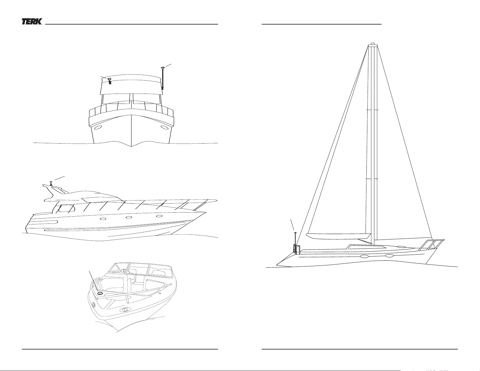
Fishing Boats
Figure 1. The TERK SIRMarine is shown installed on the fishing boat’s fly bridge, both with a
bracket and a mast mount
Sport Boats
Sailboats
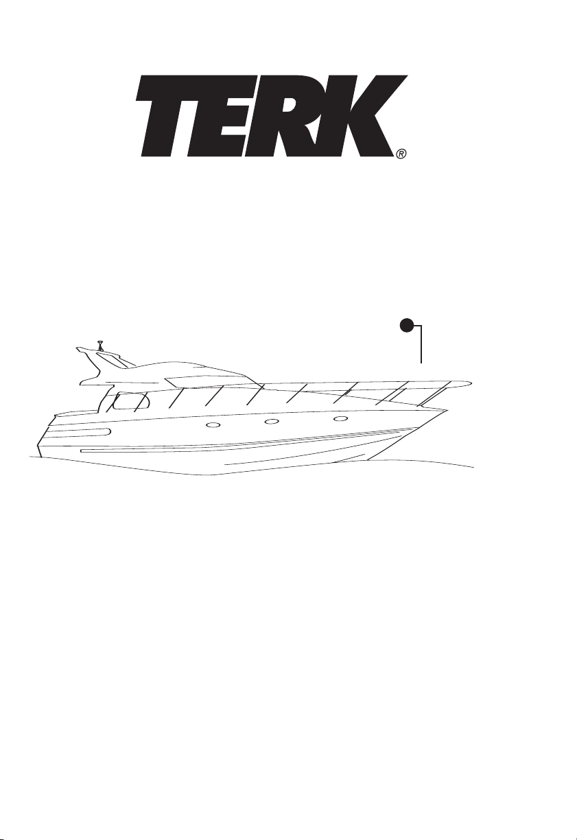
Figure 2. The TERK SIRMarine is shown mounted on the electronics arch of a sports boat.
Figure 3. The TERK SIRMarine is shown mounted on a deck or flat surface of a small boat.
4 Applications
Figure 4. The TERK SIRMarine is shown installed on an antenna extension on the stern of a sailboat.
NOTE: When mounted in this configuration, the mast and sails may interfere with reception when
the craft is at certain angles to the satellite.
Applications 5
Page 4

Clear Signals
Blocked Signals
SIRMarine
20° Clearance
Correct
SIRMarine
Incorrect
25 foot cable
Slotted
extension
adapter
SIRMarine Antenna
Threaded
Flange Adapter
Lock
Washer
Hex nut
Installation
Figure 5. Verify that your TERK SIRMarine package includes the above items.
Recommended Tools and Supplies
• Any electric drill and a 9/16 inch drill bit
• A 24mm open end or adjustable wrench to tighten hex nut when deck mounting
• Any tool to help cable routing (e.g., flat dental pick, screwdriver, etc.)
• Grommet and silicone sealer (for cable routes)
• (Optional) Antenna Extension with 1"-14 threads
• (Optional) Any mounting bracket with 1"-14 threads
Installation Precautions and Tips
• When selecting an antenna location, make sure the antenna is not enclosed by any metal material.
If a metal fly bridge is to be used, the antenna must protrude at least 5 inches above the bridge’s
top edge. Consider using an antenna extension to increase the height above the boat.
• Also, at the proposed site, verify that there is at least a 20-degree clearance from any metallic
obstruction on all sides, as shown in figure 6 (on the next page).
• Prior to installation, turn off all audio systems and other electrical devices. Disconnect the (–)
negative lead from the boat’s battery.
• At the installation site, locate and make a note of all fuel lines, cables, and electrical wiring.
Use extreme caution when cutting or drilling in and around these areas.
eye wear when using tools.
• When drilling fiberglass surfaces, use a small backup block of wood to help control splintering.
6 Installation
ways wear protective
Al
SIRMarine Owner’s Manual
Figure 6. Correct and incorrect TERK SIRMarine locations on a fishing boat.
• As you plan the cable route, avoid running the cable through any component that may cause
excessive chafing. Doing so may erode the jacket and break signal continuity. Also, avoid
kinking, pinching, excessive bending, or twisting of the cable during a run.
• Do not trim the cable length. It is optimized for best signal reception. Coil and store any excess
cable behind the Sirius receiver.
• Do not remove the connectors from the cables.
Installing the TERK SIRMarine Satellite Radio Antenna
Deck or Flat Surface Mounting
1. At the chosen site, drill a 9/16 inch mounting hole. For mounting surfaces thicker then 1/4 inch
you will need to attach the supplied slotted extension adapter to the SIRMarine antenna. Simply
route the 6 inch long antenna cable through the slot and thread the extension adapter onto the
existing antenna shaft and tighten.
2. Pass the TNC connector and the 6 inch antenna cable through the hole in the mounting surface.
3. Install the lock washer and hex nut onto the antenna shaft and tighten securely assuring that
the antenna is seated properly.
4. Attach the 25 foot coax cable to the 6 inch antenna cable by connecting the TNC connectors
securely. See figures 7 and 8 on the next page.
Continue to the
“Connecting
our Sirius Radio”
Y
o
T
section on the next pa
ge.
Continued on next page...
Installation 7
Page 5

Installation (continued)
SIRMarine
Antenna
Lock
Washer
Mounting
Surface
Hex nut
25 ft Cable
Slotted
Threaded
Adapter
SIRMarine Antenna
Antenna
Extension
(optional – length
determined
by application)
Mounting Bracket
(optional)
TNC Connector on 6” cable
Threaded Flange Adapter
25’ Coax Cable
Removable gromet to be placed over
small connector then pressed back
into mast extention
SIRMarine Owner’s Manual
Figure 9. SIRMarine Antenna with Threaded Flange Adapter for Mast mounting.
Figure 7 .
Surface Mounting
on surfaces up
to 1/4 inch thick
Figure 8 .
Surface Mounting on
surfaces 1/4 inch
thick to 1 inch thick
Mast or Bracket Mounting
The Terk SIRMarine Satellite Radio Antenna is easy to install on any standard mast or brackets that
have a 1”-14 thread.
1. Attach the Threaded Flange Adapter to the SIRMarine by first passing the TNC connector on the
6 inch antenna cable lead through the adapter as shown in Figure 9 on the next page. Next
thread the adapter on to the threaded extension of the SIRMarine and tighten securely. (Note: do
not use the supplied Slotted Threaded Adaptor in this application.
2. Connect the TNC connector on the 6 inch antenna cable lead to the mating TNC connector on
the 25 foot cable and tighten securely. The 25 foot cable can be routed through the provided
access holes and grommet that are located on the mast or bracket. Since the SMB connector
has a much smaller diameter it is recommended that you route this connector through any
access hole necessary. Many masts have grommets that can be removed which makes it easier
to route the cable through the access hole. The grommet can be placed over the SMB connector
and put back in place for a neat install.
3. Secure the SIRMarine antenna and adapter to the mast or bracket by tightening onto the 1”-14
thread securely.All mast and brackets should be installed on the boat per manufacturers specifications. If needed, adjust the tilt so that the antenna is perpendicular to the horizon.
Connecting to your Sirius Radio
1. Connect the SMB connector to the Sirius Satellite Receiver. Turn on the Sirius system and tune
the radio to channel 184 (i.e., the preview channel) to verify that the antenna is properly
installed. If there are any problems, review the installation steps and verify that each one was
performed correctly. Also see
2. After the system has been tested successfully, continue dressing the cable from the antenna to
the receiver for best appearance and complete any remaining installation. Use cable tie wraps
where needed to secure cables from fla
holes in the bulkheads with a marine grade RTV or silicon adhesive.
Note: For additional help with cable routing, consult your local marine audio dealer.
Troubleshooting on the next page.
gging in the wind and ca
tching on objects.
Seal an
y
8 Installation
Installation 9
Page 6

Use and Care
In normal daily use, the TERK SIRMarine Satellite Radio Antenna is a rugged, high-performance
antenna that does not require any special attention.
SIRMarine Owner’s Manual
X Corp. strives to maintain and exceed the highest consumer standards. Due to these on going efforts, modifications
AUDIOVO
may be made from time to time to existing products without an
those listed or sho
TERK logo are trademarks of AUDIOVOX Corp.
wn in this manual. The Sirius name and related logos are trademarks of Sirius Satellite Radio, Inc.TERK and
y prior notice. Specifications and appearance may differ from
Troubleshooting
Symptom Solutions
Sirius radio displays “Antenna” • Check antenna connections to the Sirius receiver.
or “Check Antenna” message
Sirius radio displays “No Signal” • Boat may be in an area where the Sirius signal is
message obstructed. Move the boat to more open surroundings.
Other symptoms • Call TERK for help at 1-800-942-TERK (8375) on
any business day, between 9
and ask for Technical Support.
A.M. and 5:30 P.M., EST
Specifications
Electrical
Passive Satellite Antenna Element –
Frequency 2320.0 to 2332.5 MHz
Gain 4.5 to 7 dBi from 50 to 90 deg.
Bandwidth 12.5 MHz
Impedance 50 ohms
Polarization LHCP (Circular)
LNA for Satellite Signals –
Gain 33.5 dB, typical
Noise Figure 0.8 dB, maximum
Cable Loss -12.0 dB
Current Draw 160 mA, maximum
Output VSWR 1.5:1
Input P1dB -14
About Sirius Satellite Radio
For more information about Sirius Satellite Radio service, visit their web site at:
www.siriusradio.com
Mechanical
Total Height Deck Mount -1.08 inches
Max Diameter 3.75 inches (outside)
Coax Cable 25 ft RG-174
Quality and Performance –
Temperature -40° to + 185° F (operating)
SIRIUS Approved P
Mast Mount - 3.13 inches
er SIRIUS Sa
tellite Radio Specifica
tions
About Sirius Satellite Radio 1110 Use and Care/Troubleshooting/Specifications
Page 7

12 Month Limited Warranty
For Customer Service
Visit Our Website At
www.audiovox.com
Product Information, Photos,
FAQ’s, Owner’s Manuals
VOX ELECTRONICS CORPORATION (the Company) warrants to the original retail purchaser of
AUDIO
this product that should this product or any part there of, under normal use and conditions, be proven
defective in material or workmanship within 12 months from the date of original purchase, such
ect(s) will be repaired or replaced with new or reconditioned product (at the Company's option)
def
without char
Warranty, the product is to be delivered with proof of warranty coverage (e.g. dated bill of sale),
specification of defect(s), transportation prepaid, to an approved warranty station or the Company at
the addr
static or noise, to costs incurred for installation, removal or reinstallation of the product, damage to
speakers, accessories, or vehicle and home electrical systems, malfunction of satellite transmissions,
epeater signal or receiver unit. This Warranty does not apply to any product or part thereof which, in
r
the opinion of the Company, has suff
mishandling, misuse, neglect, accident, or by removal or defacement of the factory serial number/bar
code label(s). THE EXTENT OF THE COMPANY'S LIABILITY UNDER THIS WARRANTY IS LIMITED TO
THE REPAIR OR REPLACEMENT PROVIDED ABOVE AND, IN NO EVENT, SHALL THE COMPANY'S
LIABILITY EXCEED THE PURCHASE PRICE PAID BY PURCHASER FOR THE PRODUCT. This Warranty
is in lieu of all other express warranties or liabilities. ANY IMPLIED WARRANTIES, INCLUDING ANY
IMPLIED WARRANTY OF MERCHANTABILITY, SHALL BE LIMITED TO THE DURATION OF THIS WRITTEN
WARRANTY. ANY ACTION FOR BREACH OF ANY WARRANTY HERE UNDER INCLUDING ANY IMPLIED
WARRANTY OF MERCHANTABILITY MUST BE BROUGHT WITHIN A PERIOD OF 48 MONTHS FROM DATE
OF ORIGINAL PURCHASE. IN NO CASE SHALL THE COMPANY BE LIABLE FOR ANY CONSEQUENTIAL
OR INCIDENTAL DAMAGES FOR BREACH OF THIS OR ANY OTHER WARRANTY, EXPRESS OR IMPLIED,
WHATSOEVER. No person or representative is authorized to assume for the Company any liability
other than expressed herein in connection with the sale of this product. Some states do not allow
limitations on how long an implied warranty lasts or the exclusion or limitation of incidental or
consequential damage so the above limitations or exclusions may not apply to you. This Warranty
gives you specific legal rights and you may also have other rights which vary from state to state.
ge for parts and repair labor. To obtain repair or replacement within the terms of this
ess shown below. This Warranty does not extend to the elimination of externally generated
ered or been damaged through alteration, improper installation,
For customer service and
technical information:: 1.800.290.6650
TERK and TERK logo are registered trademarks of AUDIOVOX Corp.
 Loading...