

Page 1
p ARTS ENCLOSED:
Qty.
Part
EMO20-987
EMA15-217
EMA78-242
EM178-123
EMA78-243
EMB210-107
EMB210~108
EMA226-123
EMA55-148
EMA26-104
EMC29-309
EMA15-214
EMA22-102
EMA40-102
2
2
1
Solenoid
Machine Screw
Washers (Solenoid)
E-Clip
Washer (Cable)
Wire Harness (Red)
Wire Harness (Blk.)
Tap Connector
Snap Ring
Switch Button
Switch Bracket
Bracket Screw
Cable Tie
Instruction Sheet
STEP 5. Install Switch Button.
A. Glove box installation.
If you are installing your switch in the glove box many models
have plugged holes already in them. If your vehicle is so
equipped, remove the plug. The hole may be either 3/4" or 1" in
diameter. If the hole is 1" diameter you will need to use the
optional snap ring. Glove boxes without plugged holes will
require a 3/4" diameter hole be cut (Caution: Remove glove
box insert before drilling Hole). Once your hole is located, route
the connector plugs on the black and red wires through and
connect them to the switch button. Push the switch button into
the hole.
B. Under dash installation.
If you are installing the switch button under the dash you will
need to use the switch bracket and snap ring. Remove a screw
under the dash or use the enc!osed self-tapping screw and
install the switch button bracket. Connect the wiring to the
switch button as described in above paragraph.
STEP 1. Disconnect Positive Battery Cable
STEP 2. Remove Panel From Rear Liftgate
STEP 6. Connecting the Switch Button.
Taking the blank end of the red wire determine if you wish to
connect at the fuse box or splice into an existing wire. Decide
whether you want your power source to be ignition activated c
constant and complete the connection. Your switch will be
operable upon reconnecting the battery .
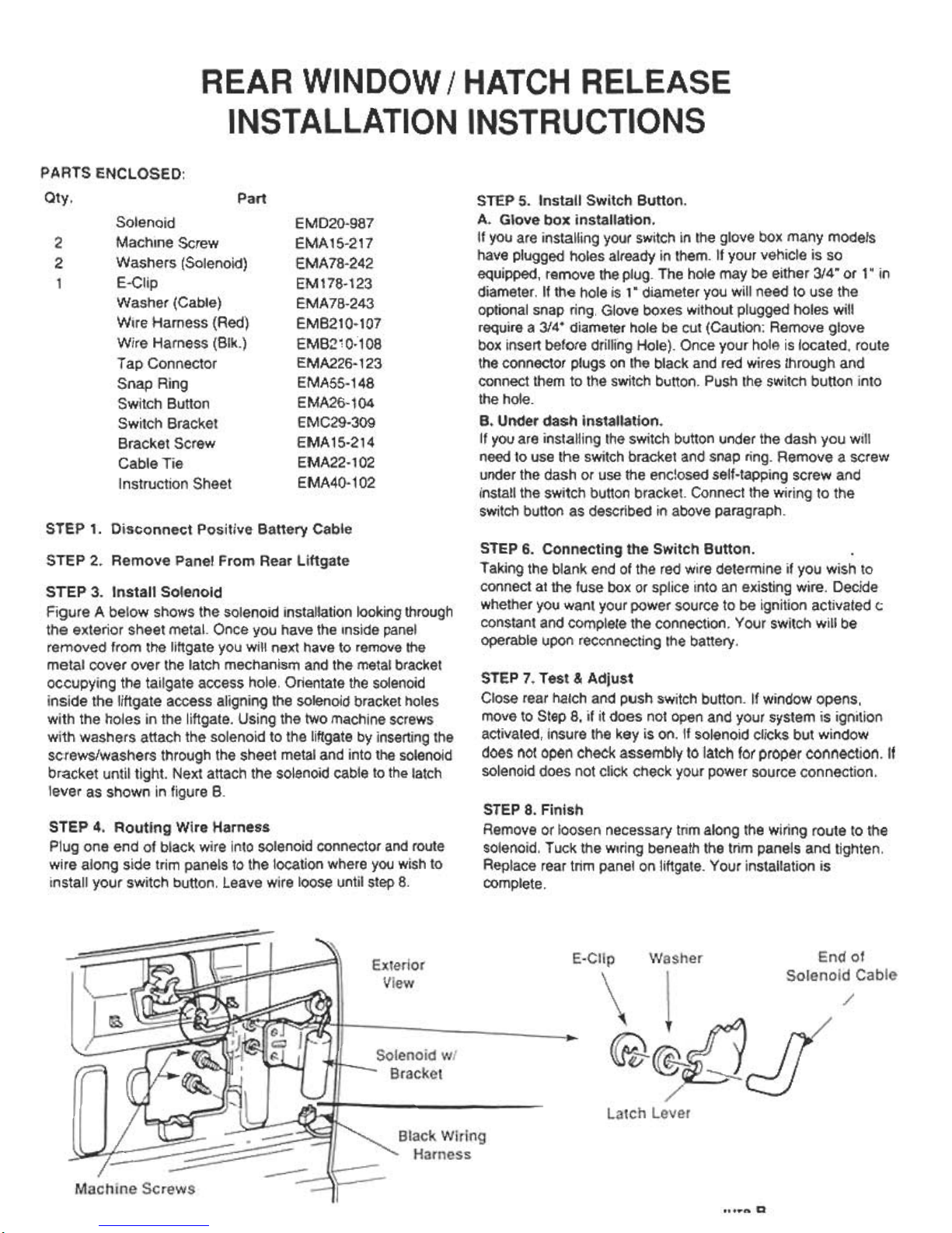
STEP 3. Install Solenoid
Figure A below shows the solenoid installation looking through
the exterior sheet metal. Once you have the inside panel
removed from the liftgate you will next have to remove the
metal cover over the latch mechanism and the metal bracket
occupying the tailgate access hole. Orientate the solenoid
inside the liftgate access aligning the solenoid bracket holes
with the holes in the liftgate. Using the two machine screws
with washers attach the solenoid to the liftgate by inserting the
screws/washers through the sheet metal and into the solenoid
bracket until tight. Next attach the solenoid cable to the latch
lever as shown in figure B.
STEP 7. Test & Adjust
Close rear hatch and push switch button. If window opens,
move to Step 8, if it does not open and your system is ignition
activated, insure the key is on. If solenoid clicks but window
does not open check assembly to latch for proper connection. If
solenoid does not click check your power source connection.
STEP 8. Finish
Remove or loosen necessary trim along the wiring route to the
solenoid. Tuck the wiring beneath the trim panels and tighten.
Replace rear trim panel on liftgate. Your installation is
complete.
STEP 4. Routing Wire Harness
Plug one end of black wire into solenoid connector and route
wire along side trim panels to the location where you wish to
install your switch button. Leave wire loose until step 8.
" a
 Loading...