

Page 1

INSTALLATION INSTRUCTIONS
FOR AUDIOVOX MODEL SW-50
DELUXE CONVERTIBLE
CAR STEREO SPEAKERS
These speakers have been designed for use with all car stereo systems and incorporate the
following deluxe features:
1. Modern, glare-broof cabinets blend well with any car decor.
2. Unique 5 inch round free edge speaker fully emphasizes .stereo effect, reproducing
both high and low tones in rich volume and with minimal distortion.
3. May be mounted either in door panels or on rear deck.
4. May also be used with car radios as well as stereo tape systems.
Installation Instructions
A. Door Panel Mounting
1. For door panel mounting, only the top portion of the speaker enclosure (cabinet A in
diagram ) is used.
2. Locate a convenient place on the door panel for the speaker to be mounted.
Note : Care should be taken to make sure speaker installation will not obstruct the
Cable Address: Audiovox Hauppauge. N. Y. / TWX: 96-7794
>1UDIOrOX.
We Make Cars More Livable^"
150 Marcus Blvd., Hauppauge, New York 11788
Telephone (516) 231-7750
raising or lowering of the window or effect the door locking mechanism.
3. A hole 2 inches by 2 '/2 inches should be made in the door panel, and in the sheet
metal behind the door, if necessary, to provide clearance for the speaker magnet.
4. The wire lead from the speaker should be fed through the door and routed towards
the location of the stereo or radio.
5. The speaker may now be mounted on the door panel using the four black self-tapping
screws which previously held the two portions of the speaker enclosure together.
B. Rear Deck Mounting
1. For rear deck mounting, the speakers may either be'installed flush against the deck
or within the wedge shaped enclosures to direct the sound forward. For flush
mounting, proceed according to A above (Door Panel Mounting). For wedge
installation proceed as follows.
2. Separate the two speaker enclosures as far as possible on rear deck to preserve
stereo effect.
3. Separate the enclosure portions (Cabinet A and Cabinet B) by removing the four
black screws.
4. Using cabinet B as a template, mark the locations of the three mounting holes and
the large square hole on the rear deck, as shown in the diagram.
5. Cut out the large hole and the three small holes and mount Cabinet B on the rear
deck using the screws and nuts provided.
6. The wire lead should be fed through the large hole and routed towards the location of
the stereo or radio.
7. Remount Cabinet A on Cabinet B using the four black self tapping screws previous-
Page 2
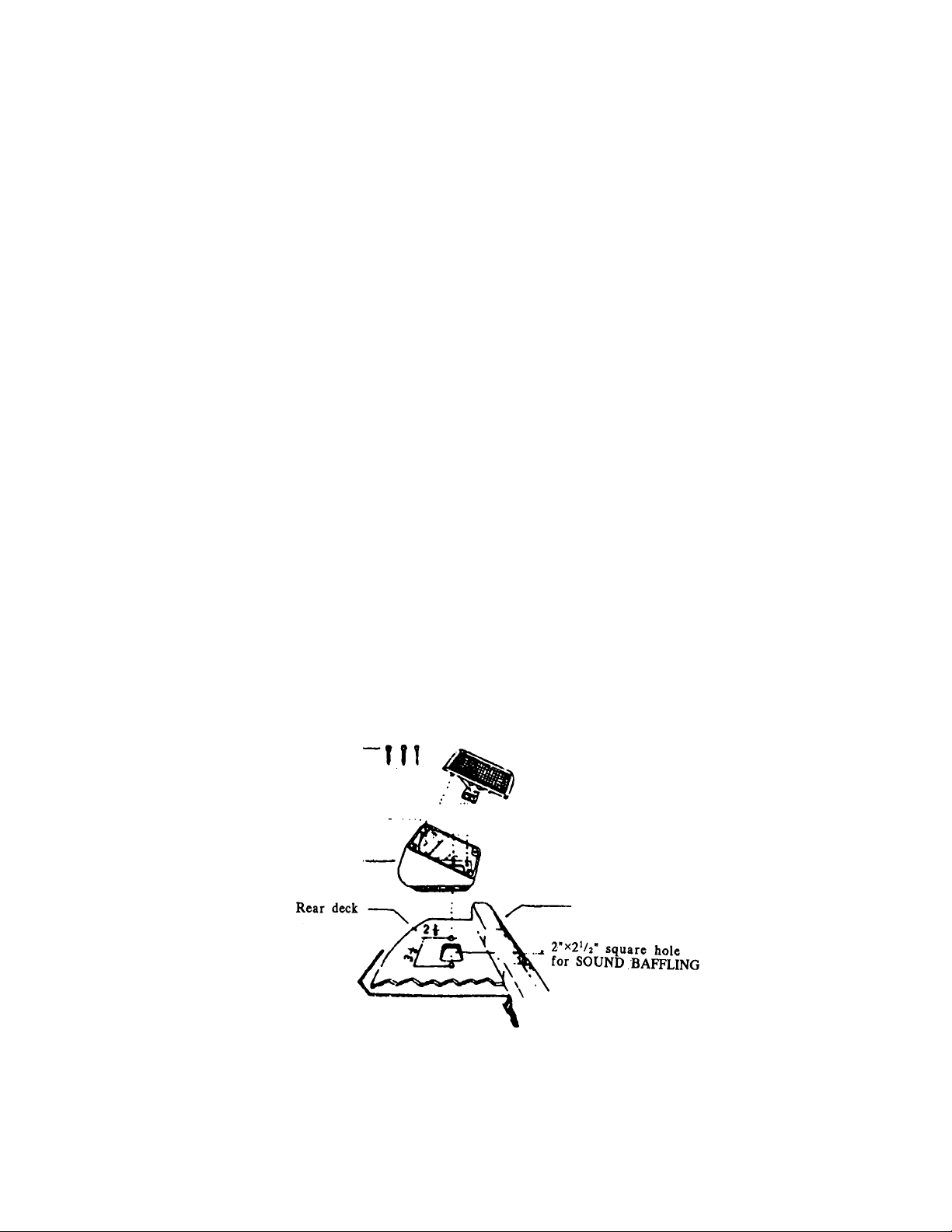
ly removed.
C. Wiring
1. When routing speaker wires, make sure they are not pinched or cut by any bare
metal edges.
2. Splice the leads from the speakers to the output leads of the tape deck or radio,
making sure to observe and maintain the polarities of the left and right channels.
Cover all exposed wires with electrical insulating tape.
3. When attaching two speakers to one output channel, correct impedance matching
must be maintained between the speakers and the stereo or radio.
Two 8 OHM speakers wired in parallel; 4 OHMS
Two 4 OHM speakers wired in series : 8 OHMS
Speaker Rating
Loudspeaker: 5 inch round, 7 oz. magnet
Impedance : 4 OHMS
Mounting Applications Side door panels, rear deck, etc.
3 Screws •
Cabinet B’
REAR DECK
SPEAKER INSTALLATION DIAGRAM
/ “ Black screw
Cabinet A with
Loud speaker
Rear seat
PRINTED IN CHINA
Page 3

, Signal Generator
Kit# 250-4171
Installation Instructions
1. Remove Plaatlc Shipping Caps from Generator Components. Asaeitible Generator Components as
illustrated below. EXCEPT the •STAMPfio Nih See Not« 1
2. You will need to work where the Vehicle Speedometer Cable is attached to the Transmission. If
necessary, raise the vehicle. Chock Wliecls,
WARNING
Do not get vndet any vehicle held up by a Jack only. Use Jack Stands or Ramps,
Tlic web of a concrete block will not bold the can DO NOT RISK YOUR UFBt
A. Disconnect Vehicle Speedometer Cable from Transmission.
B. Connect Speedometer Cable to Tang Drive Adapter, Scat Speedometer Cable into
Tang Drive Adapter Slot, tighten Speedometer Cable. See Note i
C. Install Generator Assembly Into tiansmisslon housing. Turn Signal GfiNERAroR so wires
wiD not catch on objects while driving. Tighten Nut.
TOEKISTINC
SPEEDOMETER
CABLE
NOTEl
After Cable Is assembled, insert Adapter Kkt Into other
end and rotate Drive Cable. If Cable wUl not rotate,
remove Tano Drive Adapter and install ^Stamped Nxrr
(5/8-18} In position shown. Reinstall Tamg Drive Adapter.
This will allow elearance between Speedometer Drive
Cable Inner Core Wire and Signal Generator Assembly.
rml 2I№7
6/99 №f a
Page 4

4. Plug BxTEHBion Harness into Signal Gbneratob Lead. Select , proper plastic oonneetjor for system
being installed and insert iemitnals of Extension Harness Lead into plastic Cohmecto» as shown.
For Cruise Control Systems using Signal Generator Harness to Main Wiring Hamesa connection, use
Harness Connector and insert wires as shown.
HARNESS
CONNECTOR
For Cruise Control Systems using Signal Generator Harness to Module connection, use Mooule
Connector and Insert wires as shown,
‘GRAT
-KETWAT
MODULE
CONNECTOR
‘DKBLUE
5. Route -wtres using Wire Ties to support wires, as necessary, keeping them away from any Hot,
Sharp or Moving parts of vehicle.
IMPORTANT
This Signal Geherator produces an SOOO Pulses/MUe (5000 Pnlses/KUomieter] Sine
Wave Signal. Sec Page 7 of your Cruise Control Installation Guide to correctly set your
Programming Switches. If you do not correctly set your Cruise Control Programming
Switches for an 8000 PPM (5000 PPK) Sine Wave Signal, your Cruise Control will not
function properly.
SERVICE РАЯТ5
250-2264 Kit Includes Harness Connector, Module Connector and Extension Harness
250-2265 Kit Includes Tang Drive Аплртеа, Asapter Key and 5/8-18 Stamped Nut
250-2266 Kit Includes Metric Adapter, Metric Adapter Key and M22 Ntrt
260-3239 Kit Includes Signal Generator
Rostra Precision Controls. Inc.
Global Automotive Accessories Group
2519 Dana Drive
Laurinbuig. NC 28352-4000
WWW, rostr a,com
Certified QS 9000/ISO 9001
Made In the U.S.A.
 Loading...